turn signal JEEP RENEGADE 2023 User Guide
[x] Cancel search | Manufacturer: JEEP, Model Year: 2023, Model line: RENEGADE, Model: JEEP RENEGADE 2023Pages: 364, PDF Size: 18.65 MB
Page 75 of 364
GETTING TO KNOW YOUR INSTRUMENT PANEL 73
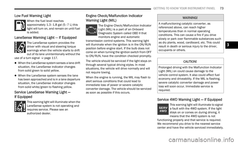
Low Fuel Warning Light
When the fuel level reaches
approximately 1.3–1.8 gal (5–7 L) this
light
will turn on, and remain on until fuel
is added.
LaneSense Warning Light — If Equipped
The LaneSense system provides the
driver with visual and steering torque
warni n
gs when the vehicle starts to drift
out of its lane unintentionally without the
use of a turn signal Ú page 117.
When the LaneSense system senses a lane drift
situation, the LaneSense indicator changes
from solid green to solid yellow.
When the LaneSense system senses the lane
has been approached and is in a lane departure
situation, the LaneSense indicator changes
from solid white/green to flashing yellow.
Service LaneSense Warning Light —
If Equipped
This warning light will illuminate when the
LaneSense system is not operating and
r e q
ui
r
es service. Please see an
authorized dealer.
Engine Check/Malfunction Indicator
Warning Light (MIL)
The Engine Check/Malfunction Indicator
Light (MIL) is a part of an Onboard
D ia
gn
os
tic System called OBD II that
monitors engine and automatic
transmission control systems. This warning light
will illuminate when the ignition is in the ON/RUN
position before engine start. If the bulb does not
come on when turning the ignition switch from OFF
to ON/RUN, have the condition checked promptly.
The vehicle should be serviced if the light stays on
throug h
several typical driving styles. In most
situations, the vehicle will drive normally and will
not require towing.
When the engine is running, the MIL may flash to
alert
serious conditions that could lead to
immediate loss of power or severe catalytic
converter damage. The vehicle should be serviced
as soon as possible if this occurs.
Service 4WD Warning Light — If Equipped
This warning light will illuminate to signal
a fault with the 4WD system. If the light
stays
on or comes on during driving, it
means that the 4WD system is not
functioning properly and that service is required.
We recommend you drive to the nearest service
center and have the vehicle serviced immediately.
WARNING!
A malfunctioning catalytic converter, as
referenced above, can reach higher
temperatures than in normal operating
conditions. This can cause a fire if you drive
slowly or park over flammable substances such
as dry plants, wood, cardboard, etc. This could
result in death or serious injury to the driver,
occupants or others.
CAUTION!
Prolonged driving with the Malfunction Indicator
Light (MIL) on could cause damage to the
vehicle control system. It also could affect fuel
economy and driveability. If the MIL is flashing,
severe catalytic converter damage and power
loss will soon occur. Immediate service is
required.
3
Page 78 of 364
76 GETTING TO KNOW YOUR INSTRUMENT PANEL
at speeds greater than 30 mph (48 km/h), see an
authori
zed dealer as soon as possible to have the
problem diagnosed and corrected.
The ESC OFF Indicator Light and the ESC Indi -
cator Light come on momentarily each time the
ignit i
on is placed in the ON/RUN or ACC/ON/
RUN position.
The ESC system will make buzzing or clicking
sounds when it is active. This is normal; the
sounds will stop when ESC becomes inactive.
This light will come on when the vehicle is in an
ESC event.
Electronic Stability Control (ESC) OFF
Warning Light — If Equipped
This warning light indicates the ESC is off.
Each time the ignition is turned to ON/
RUN or
ACC/ON/RUN, the ESC system
will be on, even if it was turned off previously.
Exterior Bulb Failure Indicator Light —
If Equipped
This light will illuminate when there is a
malfunction in one of the exterior bulbs.
Fuel Cutoff Warning Light — If Equipped
This warning light will illuminate after an
accident has occurred, and the system
has s h
ut the fuel off.
Fuel Cutoff Failure Light — If Equipped
This light will illuminate if there is a fuel
cutoff failure. If this light illuminates, take
it to a
n authorized dealer and have them
inspect it.
Immobilizer Fail / VPS Electrical Alarm
Indicator Light
This telltale will illuminate when the
vehicle security system has detected an
a tt
e m
p
t to break into the vehicle.
NOTE:
After cycling the ignition to the ON/RUN position,
the V e
hicle Security Warning Light could illuminate
if a problem with the system is detected. This
condition will result in the engine being shut off
after two seconds.
GREEN INDICATOR LIGHTS
Automatic High Beam Indicator Light —
If Equipped
This indicator shows that the automatic
high beam headlights are on.
Cruise Control Set Indicator Light
This light will turn on when the cruise
control is set to the desired speed
Ú page 95.
Front Fog Indicator Light — If Equipped
This indicator light will illuminate when
the front fog lights are on Ú page 36.
Hazard Warning Lights
The hazard warning indicators light up
when the vehicles Hazard Warning
flash e
r switch has been pushed.
Parking/Headlights On Indicator Light
This indicator light will illuminate when
the parking lights or headlights are
tu r
n e
d
on Ú page 36.
Sport Mode Indicator Light — If Equipped
This light will turn on when Sport Mode is
active.
Stop/Start Active Indicator Light —
If Equipped
This indicator light will illuminate when
the Stop/Start function is in “Autostop”
mode.
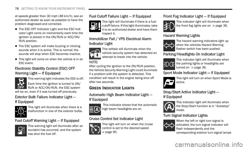
Turn Signal Indicator Lights
When the left or right turn signal is
activated, the turn signal indicator will
f la
sh
independently and the
corresponding exterior turn signal lamps
Page 79 of 364
GETTING TO KNOW YOUR INSTRUMENT PANEL 77
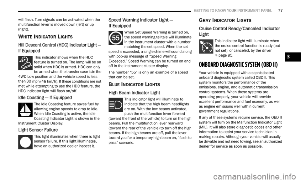
will flash. Turn signals can be activated when the
multifunction lever is moved down (left) or up
(right).
WHITE INDICATOR LIGHTS
Hill Descent Control (HDC) Indicator Light —
If Equipped
This indicator shows when the HDC
feature is turned on. The lamp will be on
solid w
hen HDC is armed. HDC can only
be armed when the transfer case is in the
4WD Low position and the vehicle speed is less
then 30 mph (48 km/h). If these conditions are not
met wh
ile attempting to use the HDC feature, the
HDC indicator light will flash on/off.
Idle Coasting — If Equipped
The Idle Coasting feature saves fuel by
allowing engine speeds to drop to idle.
W he
n
I
dle Coasting is active, the Idle
Coasting Indicator Light is shown in the
Instrument Cluster Display.
Light Sensor Failure
This light illuminates when there is light
sensor failure. If this light illuminates,
have a
n authorized dealer inspect it.
Speed Warning Indicator Light —
If Equipped
When Set Speed Warning is turned on,
the speed warning telltale will illuminate
i n
t h
e
instrument cluster with a number
matching the set speed. When the set
speed is exceeded, a single chime will sound along
with pop-up message of “Speed Warning
Exceeded.” Speed Warning can be turned on and
off in the instrument cluster display.
The number “55” is only an example of a speed
that c
an be set.
BLUE INDICATOR LIGHTS
High Beam Indicator Light
This indicator light will illuminate to
indicate that the high beam headlights
are on .
With the low beams activated,
push the multifunction lever forward
(toward the front of the vehicle) to turn on the high
beams. Pull the multifunction lever rearward
(toward the rear of the vehicle) to turn off the high
beams. If the high beams are off, pull the lever
toward you for a temporary high beam on, “flash to
pass” scenario.
GRAY INDICATOR LIGHTS
Cruise Control Ready/Canceled Indicator
Light
This indicator light will illuminate when
the cruise control function is ready (but
not se t
), or canceled, by the driver
Ú page 95.
ONBOARD DIAGNOSTIC SYSTEM (OBD II)
Your vehicle is equipped with a sophisticated
onboard diagnostic system called OBD II. This
system monitors the performance of the
emissions, engine, and automatic transmission
control systems. When these systems are
operating properly, your vehicle will provide
excellent performance and fuel economy, as well
as engine emissions well within current
government regulations.
If any of these systems require service, the OBD II
syste m
will turn on the Malfunction Indicator Light
(MIL). It will also store diagnostic codes and other
information to assist your service technician in
making repairs. Although your vehicle will usually
be drivable and not need towing, see an authorized
dealer for service as soon as possible.
3
Page 103 of 364
STARTING AND OPERATING 101
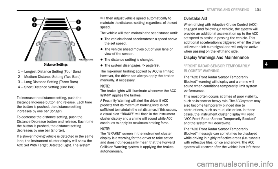
Distance Settings
To increase the distance setting, push the
Distan
ce Increase button and release. Each time
the button is pushed, the distance setting
increases by one bar (longer).
To decrease the distance setting, push the
Distan
ce Decrease button and release. Each time
the button is pushed, the distance setting
decreases by one bar (shorter).
If a slower moving vehicle is detected in the same
lane,
the instrument cluster display will show the
ACC Set With Target Detected Light. The system will then adjust vehicle speed automatically to
maintain the distance setting, regardless of the set
speed.
The vehicle will then maintain the set distance until:
The vehicle ahead accelerates to a speed above
the set speed.
The vehicle ahead moves out of your lane or
view of the sensor.
The distance setting is changed.
The system disengages
Ú page 99.
The maximum braking applied by ACC is limited;
howeve r
, the driver can always apply the brakes
manually, if necessary.
NOTE:
The brake lights will illuminate whenever the ACC
syste m
applies the brakes.
A Proximity Warning will alert the driver if ACC
predic
ts that its maximum braking level is not
sufficient to maintain the set distance. If this occurs,
a visual alert “BRAKE!” will flash in the instrument
cluster display and a chime will sound while ACC
continues to apply its maximum braking force.
NOTE:
The “BRAKE!” screen in the instrument cluster
displ a
y is a warning for the driver to take action
and does not necessarily mean that the Forward
Collision Warning system is applying the brakes
autonomously.
Overtake Aid
When driving with Adaptive Cruise Control (ACC)
engaged and following a vehicle, the system will
provide an additional acceleration up to the ACC
set speed to assist in passing the vehicle. This
additional acceleration is triggered when the driver
utilizes the left turn signal and will only be active
when passing on the left hand side.
Display Warnings And Maintenance
“FRONT RADAR SENSOR TEMPORARILY
BLOCKED” WARNING
The “ACC Front Radar Sensor Temporarily
Blocked” warning will display and a chime will
sound when conditions temporarily limit system
performance.
This most often occurs at times of poor visibility,
such a
s in snow or heavy rain. The ACC system may
also become temporarily blinded due to
obstructions, such as mud, dirt or ice. In these
cases, the instrument cluster display will read
“ACC Front Radar Sensor Temporarily Blocked”
and the system will deactivate.
The “ACC Front Radar Sensor Temporarily
Blocke d
” message can sometimes be displayed
while driving in highly reflective areas (i.e. tunnels
with reflective tiles, or ice and snow). The ACC
system will recover after the vehicle has left these
1 — Longest Distance Setting (Four Bars)
2 — Medium Distance Setting (Two Bars)
3 — Long Distance Setting (Three Bars)
4 — Short Distance Setting (One Bar)
4
Page 112 of 364

110 STARTING AND OPERATING
The system warns the driver with an acoustic
signal and where provided, with visual indications
on the instrument panel display.
NOTE:
Parksense will reduce the volume of the radio if
on when the system is sounding an audible
tone.
The alert chime is activated only when the
obstacle is in the vehicle path.
Activation — Deactivation
The system can operate only after driving a short
distance and if the vehicle speed is between 0 and
11
mph (0 and 18 km/h). The system can be
activa
ted/deactivated via the "Settings" menu of
the Uconnect system. If the ParkSense System is
deactivated via the ParkSense Hard switch then
the Side Distance Warning system will
automatically be deactivated.
Message on the display for Side Distance Warning
featu r
e:
“Wipe Sensors” — This message is displayed in the
case o
f a failure of the Side Distance Warning
system sensors. Free the bumpers of any
obstacles, ensure that the front and rear bumper
are free of snow, ice, mud, dirt and debris to keep
the ParkSense system operating properly.
“SDW Not Available” — This message is displayed
if the
Side Distance Warning system is not
available. The failed operation of the system might
be due to the insufficient voltage from the battery
or other failures on the electrical system. Contact
an authorized dealer as soon as possible to have
the electrical system checked.
Operation With A Trailer
The system is automatically deactivated when the
trailer's electric plug is inserted in the vehicle's tow
hook socket. The rear sensors are automatically
reactivated when the trailer's cable plug is
removed.
ParkSense Usage Precautions
Some conditions may influence the performance
of the Side Distance Warning system:
NOTE:
Ensure that the front and rear bumper are free
of snow, ice, mud, dirt and debris to keep the
ParkSense system operating properly.
Construction equipment, large trucks, and other
vibrations could affect the performance of Park -
Sense.
When you turn ParkSense off, the message to
appear in the instrument cluster display will
read “PARKSENSE OFF.” Furthermore, once you
turn ParkSense off, it remains off until you turn
it on again, even if you cycle the ignition key.
ParkSense, when on, will reduce the volume of
the radio when it is sounding a tone.
WARNING ALERTS
Distance
(inches/cm) Less than
12 inc h
es
( 3 0
c
m
) 12–65
inches
(30–6 0
cm)
Arcs-Left 11th Flashing 12th Flashing
Arcs-Right 11th Flashing 12th Flashing
Audible Alert Chime C
on
tinuousAudible chime
incre
a
ses as
the objects within the
vehicle’s path get close to the vehicle
Radio Volume Reduc e
d Yes
Yes
Page 115 of 364
STARTING AND OPERATING 113
PARALLEL/PERPENDICULAR PARKING
S
PACE ASSISTANCE OPERATION
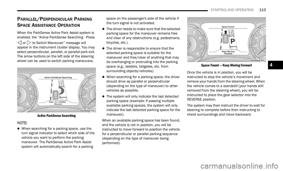
When the ParkSense Active Park Assist system is
enabled, the “Active ParkSense Searching - Press
or to Switch Maneuver” message will
appear in the instrument cluster display. You may
select
perpendicular, parallel, or parallel park exit.
The arrow buttons on the left side of the steering
wheel can be used to switch parking maneuvers.
Active ParkSense Searching
NOTE:
When searching for a parking space, use the
turn signal indicator to select which side of the
vehicle you want to perform the parking
maneuver. The ParkSense Active Park Assist
system will automatically search for a parking space on the passenger's side of the vehicle if
the turn signal is not activated.
The driver needs to make sure that the selected
parking space for the maneuver remains free
and clear of any obstructions (e.g. pedestrians,
bicycles, etc.).
The driver is responsible to ensure that the
selected parking space is suitable for the
maneuver and free/clear of anything that may
be overhanging or protruding into the parking
space (e.g., ladders, tailgates, etc. from
surrounding objects/vehicles).
When searching for a parking space, the driver
should drive as parallel or perpendicular
(depending on the type of maneuver) to other
vehicles as possible.
The system will only indicate the last detected
parking space (example: if passing multiple
available parking spaces, the system will only
indicate the last detected parking space for the
maneuver).
When an available parking space has been found,
and t h
e vehicle is not in position, you will be
instructed to move forward to position the vehicle
for a perpendicular or parallel parking sequence
(depending on the type of maneuver being
performed).
Space Found — Keep Moving Forward
Once the vehicle is in position, you will be
instr u
cted to stop the vehicle’s movement and
remove your hands from the steering wheel. When
the vehicle comes to a standstill (your hands still
removed from the steering wheel), you will be
instructed to place the gear selector into the
REVERSE position.
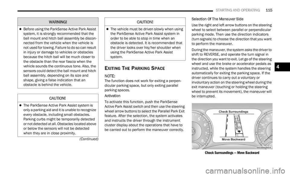
The system may then instruct the driver to wait for
steer i
ng to complete before then instructing to
check surroundings and move backward.
4
Page 117 of 364
STARTING AND OPERATING 115
(Continued)
EXITING THE PARKING SPACE
NOTE:
The function does not work for exiting a perpen -
dicular parking space, but only exiting parallel
p arki n
g spaces.
Activation
To activate this function, push the ParkSense
Activ e
Park Assist switch and then use the steering
wheel arrow buttons to select the Parallel Park Exit
feature. After the selection, the system activates
and instructs the driver through the instrument
cluster display about the operations that have to
be carried out to perform the maneuver correctly. Selection Of The Maneuver Side
Use the right and left arrow buttons on the steering
wheel
to select between parallel or perpendicular
parking mode. Then use the direction indicators
(turn signals) to choose the direction that you want
to perform the maneuver.
During the maneuver, the system asks the driver to
shift
to REVERSE, and operate the turn signal in
the direction you want to exit. Let go of the steering
wheel and use the brake or accelerator pedals as
instructed, while the system handles the steering
automatically for exiting the parking space. If the
driver continues to carry out a voluntary or
involuntary action on the steering wheel during the
exit maneuver (touching or holding the steering
wheel to prevent its movement), the maneuver will
be interrupted.
Check Surroundings — Move Backward
Before using the ParkSense Active Park Assist
system, it is strongly recommended that the
ball mount and hitch ball assembly be discon -
nected from the vehicle when the vehicle is
not us e
d for towing. Failure to do so can result
in injury or damage to vehicles or obstacles
because the hitch ball will be much closer to
the obstacle than the rear fascia when the
vehicle sounds the continuous tone. Also, the
sensors could detect the ball mount and hitch
ball assembly, depending on its size and
shape, giving a false indication that an
obstacle is behind the vehicle.
CAUTION!
The ParkSense Active Park Assist system is
only a parking aid and it is unable to recognize
every obstacle, including small obstacles.
Parking curbs might be temporarily detected
or not detected at all. Obstacles located above
or below the sensors will not be detected
when they are in close proximity.
WARNING!
The vehicle must be driven slowly when using
the ParkSense Active Park Assist system in
order to be able to stop in time when an
obstacle is detected. It is recommended that
the driver looks over his/her shoulder when
using the ParkSense Active Park Assist
system.
CAUTION!
4
Page 119 of 364
STARTING AND OPERATING 117
LANESENSE — IF EQUIPPED
LANESENSE OPERATION
The LaneSense system is operational at speeds
above 37 mph (60 km/h) and below 112 mph
(180 km
/h). The LaneSense system uses a
f or
wa
rd
looking camera to detect lane markings
and measure vehicle position within the lane
boundaries.
When both lane markings are detected and the
driver
unintentionally drifts out of the lane (no turn
signal applied), the LaneSense system provides a
haptic warning in the form of torque applied to the
steering wheel to prompt the driver to remain within
the lane boundaries. If the driver continues to
unintentionally drift out of the lane, the LaneSense
system provides a visual warning through the
instrument cluster display to prompt the driver to
remain within the lane boundaries.
The driver may manually override the haptic warning
by app l
ying torque to the steering wheel at any time.
When only a single lane marking is detected and
the dr
iver unintentionally drifts across the lane
marking (no turn signal applied), the LaneSense
system provides a visual warning through the
instrument cluster display to prompt the driver to
remain within the lane. When only a single lane
marking is detected, a haptic (torque) warning will
not be provided.
NOTE:
When operating conditions have been met, the
LaneSe n
se system will monitor if the driver’s
hands are on the steering wheel and provides an
audible warning to the driver when the driver’s
hands are not detected on the steering wheel. The
system will cancel if the driver does not return their
hands to the wheel.
TURNING LANESENSE ON OR OFF
The LaneSense button is located on the
center stack.
To turn the LaneSense system on, push the
La neSen
se button (LED turns off). A “Lane Sense
On” message is shown in the instrument cluster
display.
To turn the LaneSense system off, push the
LaneSen
se button once (LED turns on).
NOTE:
The LaneSense system will retain the last system
state
on or off from the last ignition cycle when the
ignition is changed to the ON/RUN position.
LANESENSE WARNING MESSAGE
The LaneSense system will indicate the current
lane drift condition through the instrument cluster
display.
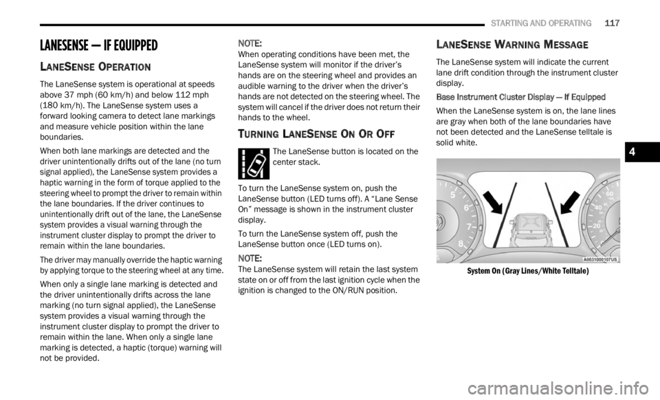
Base Instrument Cluster Display — If Equipped
When the LaneSense system is on, the lane lines
a re gr
ay when both of the lane boundaries have
not been detected and the LaneSense telltale is
solid white.
System On (Gray Lines/White Telltale)
4
Page 123 of 364
STARTING AND OPERATING 121
CHANGING LANESENSE STATUS
The LaneSense system has settings to adjust the
intensity of the torque warning and the warning
zone sensitivity (early/late) that you can configure
through the Uconnect system
Ú page 133.
NOTE:
When enabled the system operates above
37 mph (60 km/h) and below 112 mph
(180 km
/h).
Use of the turn signal suppresses the warnings.
The system will not apply torque to the steering
wheel whenever a safety system engages
(Anti-Lock Brakes, Traction Control System,
Electronic Stability Control, Forward Collision
Warning, etc.).
REAR BACK UP CAMERA
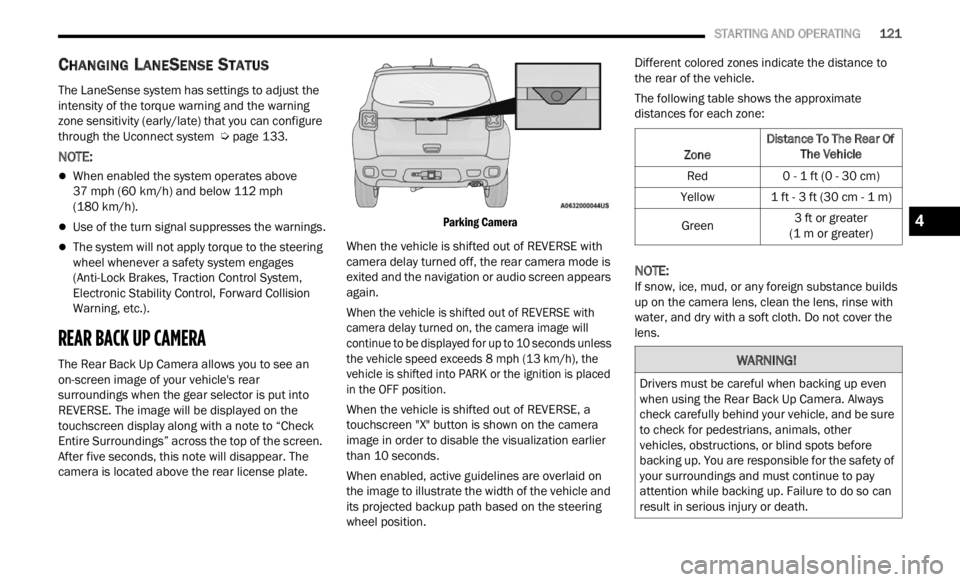
The Rear Back Up Camera allows you to see an
on-screen image of your vehicle's rear
surroundings when the gear selector is put into
REVERSE. The image will be displayed on the
touchscreen display along with a note to “Check
Entire Surroundings” across the top of the screen.
After five seconds, this note will disappear. The
camera is located above the rear license plate.
Parking Camera
When the vehicle is shifted out of REVERSE with
camer a
delay turned off, the rear camera mode is
exited and the navigation or audio screen appears
again.
When the vehicle is shifted out of REVERSE with
camera
delay turned on, the camera image will
continue to be displayed for up to 10 seconds unless
the vehicle speed exceeds 8 mph (13 km/h), the
vehic l
e is shifted into PARK or the ignition is placed
in the OFF position.
When the vehicle is shifted out of REVERSE, a
touchs c
reen "X" button is shown on the camera
image in order to disable the visualization earlier
than 10 seconds.
When enabled, active guidelines are overlaid on
the im
age to illustrate the width of the vehicle and
its projected backup path based on the steering
wheel position. Different colored zones indicate the distance to
the r
e
ar of the vehicle.
The following table shows the approximate
distan
ces for each zone:
NOTE:
If snow, ice, mud, or any foreign substance builds
up on t
he camera lens, clean the lens, rinse with
water, and dry with a soft cloth. Do not cover the
lens.
Zone Distance To The Rear Of
The Ve hicle
Red 0 - 1 ft (0 - 30 cm)
Yellow 1 ft - 3 ft (30 cm - 1 m)
Green 3
ft or greater
(1 m or
greater)
WARNING!
Drivers must be careful when backing up even
when using the Rear Back Up Camera. Always
check carefully behind your vehicle, and be sure
to check for pedestrians, animals, other
vehicles, obstructions, or blind spots before
backing up. You are responsible for the safety of
your surroundings and must continue to pay
attention while backing up. Failure to do so can
result in serious injury or death.
4
Page 130 of 364
128 STARTING AND OPERATING
Towing Requirements — Trailer Lights And
Wiring (If Equipped)
Whenever you pull a trailer, regardless of the trailer
size, stoplights and turn signals on the trailer are
required for motoring safety.
The Trailer Tow Package may include a four-pin
and s e
ven-pin wiring harness. Use a factory
approved trailer harness and connector.
NOTE:
Do not cut or splice wiring into the vehicle’s wiring
harne s
s. The electrical connections are all complete to the
vehic
l
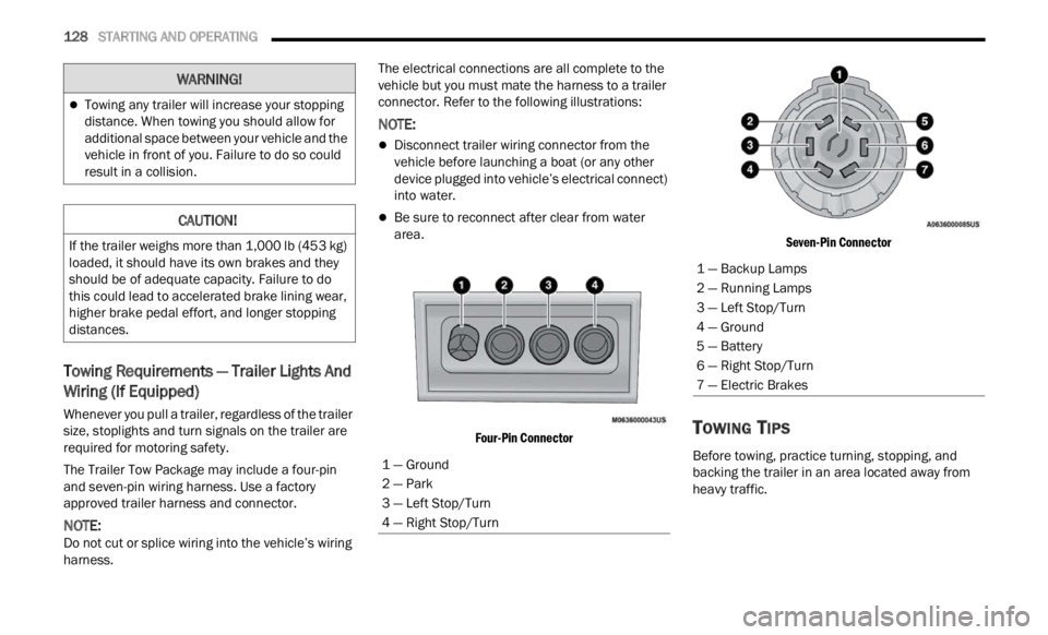
e but you must mate the harness to a trailer
connector. Refer to the following illustrations:
NOTE:
Disconnect trailer wiring connector from the
vehicle before launching a boat (or any other
device plugged into vehicle’s electrical connect)
into water.
Be sure to reconnect after clear from water
area.
Four-Pin Connector Seven-Pin Connector
TOWING TIPS
Before towing, practice turning, stopping, and
backing the trailer in an area located away from
heavy traffic.
Towing any trailer will increase your stopping
distance. When towing you should allow for
additional space between your vehicle and the
vehicle in front of you. Failure to do so could
result in a collision.
CAUTION!
If the trailer weighs more than 1,000 lb (453 kg)
loaded, it should have its own brakes and they
should be of adequate capacity. Failure to do
this could lead to accelerated brake lining wear,
higher brake pedal effort, and longer stopping
distances.
WARNING!
1 — Ground
2 — Park
3 — Left Stop/Turn
4 — Right Stop/Turn
1 — Backup Lamps
2 — Running Lamps
3 — Left Stop/Turn
4 — Ground
5 — Battery
6 — Right Stop/Turn
7 — Electric Brakes