tow JEEP RENEGADE 2023 Owner's Manual
[x] Cancel search | Manufacturer: JEEP, Model Year: 2023, Model line: RENEGADE, Model: JEEP RENEGADE 2023Pages: 364, PDF Size: 18.65 MB
Page 90 of 364

88 STARTING AND OPERATING
The following indicators should be used to ensure
that you have properly engaged the transmission
into the PARK position:
When shifting into PARK, press the lock button
on the gear selector, and firmly move the gear
selector all the way forward until it stops and is
fully seated.
Look at the transmission gear position display
and verify that it indicates the PARK position (P),
and is not blinking.
With the brake pedal released, verify that the
gear selector will not move out of PARK.
REVERSE (R)
This range is for moving the vehicle backward.
Shift
into REVERSE only after the vehicle has come
to a complete stop.
NEUTRAL (N)
Use this range when the vehicle is standing for
p rolonge
d periods with the engine running. The
engine may be started in this range. Apply the
Electric Park Brake and shift the transmission into
PARK if you must exit the vehicle. DRIVE (D)
This range should be used for most city and
highwa
y driving. It provides the smoothest upshifts
and downshifts, and the best fuel economy. The
transmission automatically upshifts through all
forward gears.
When frequent transmission shifting occurs (such
as wh e
n operating the vehicle under heavy loading
conditions, in hilly terrain, traveling into strong
head winds or while towing a heavy trailer), use the
AutoStick shift control to select a lower gear. Under
Never leave children alone in a vehicle, or with
access to an unlocked vehicle. Allowing chil -
dren to be in a vehicle unattended is
d anger
ous for a number of reasons. A child or
others could be seriously or fatally injured.
Children should be warned not to touch the
parking brake, brake pedal or the transmis -
sion gear selector.
Do not leave the key fob in or near the vehicle
(or in a location accessible to children), and do
not leave the ignition in the ON/RUN position.
A child could operate power windows, other
controls, or move the vehicle.
CAUTION!
Before moving the transmission gear selector
out of PARK, you must turn the ignition to the
ON/RUN position, and also press the brake
pedal. Otherwise, damage to the gear selector
could result.
DO NOT race the engine when shifting from
PARK or NEUTRAL into another gear range, as
this can damage the drivetrain.
WARNING!WARNING!
Do not coast in NEUTRAL and never turn off the
ignition to coast down a hill. These are unsafe
practices that limit your response to changing
traffic or road conditions. You might lose control
of the vehicle and have a collision.
CAUTION!
Towing the vehicle, coasting, or driving for any
other reason with the transmission in NEUTRAL
can cause severe transmission damage.
For Recreational Towing Ú page 129.
For Towing A Disabled Vehicle Ú page 283.
Page 91 of 364

STARTING AND OPERATING 89
these conditions, using a lower gear will improve
performance and extend transmission life by
reducing excessive shifting and heat buildup.
If the transmission temperature exceeds normal
operat i
ng limits, the transmission controller may
modify the transmission shift schedule, reduce
engine torque, and/or expand the range of torque
converter clutch engagement. This is done to
prevent transmission damage due to overheating.
If the transmission becomes extremely hot, the
Trans m
ission Temperature Warning Light may
illuminate and the transmission may operate
differently until the transmission cools down.
During cold temperatures, transmission operation
may be
modified depending on engine and
transmission temperature as well as vehicle
speed. This feature improves warm up time of the
engine and transmission to achieve maximum
efficiency. Engagement of the torque converter
clutch, and shifts into EIGHTH or NINTH gear, are
inhibited until the transmission fluid is warm.
Normal operation will resume once the
transmission temperature has risen to a suitable
level.
AutoStick
AutoStick is a driver-interactive transmission
f eatu r
e providing manual shift control, giving you
more control of the vehicle. AutoStick allows you to
maximize engine braking, eliminate undesirable
upshifts and downshifts, and improve overall vehicle performance. This system can also provide
you with more control during passing, city driving,
cold slippery conditions, mountain driving, trailer
towing and many other situations.
Operation
When the gear selector is in the AutoStick position
(besi
d
e the DRIVE position), it can be moved
forward and rearward. This allows the driver to
manually select the transmission gear being used.
Moving the gear selector forward (-) triggers a
downshift, and rearward (+) an upshift. The current
gear is displayed in the instrument cluster.
NOTE:
In AutoStick mode, the transmission will only shift
up or d
own when the driver moves the gear
selector rearward (+) or forward (-), except as
described below:
The transmission will automatically upshift
when necessary to prevent engine overspeed.
The transmission will automatically downshift
as the vehicle slows (to prevent engine lugging)
and will display the current gear.
The transmission will automatically downshift to
FIRST or SECOND gear (depending on model)
when coming to a stop. After a stop, the driver
should manually upshift (+) the transmission as
the vehicle is accelerated.
You can start out (from a stop) in FIRST or
SECOND gear. Starting out in SECOND gear can
be helpful in snow or icy conditions. Tap the gear
selector forward or rearward to select the
desired gear after the vehicle is brought to a
stop.
If a requested downshift would cause the
engine to overspeed, that shift will not occur.
The system will ignore attempts to upshift at too
low of a vehicle speed.
Avoid using Cruise Control when AutoStick is
engaged because the transmission will not shift
automatically.
Transmission shifting will be more noticeable
when AutoStick is enabled.
The system may revert to automatic shift mode
if a fault or overheat condition is detected.
To disengage AutoStick mode, return the gear
select
or to the DRIVE position. You can shift in or
out of the AutoStick position at any time without
taking your foot off the accelerator pedal.
WARNING!
Do not downshift for additional engine braking
on a slippery surface. The drive wheels could
lose their grip and the vehicle could skid,
causing a collision or personal injury.
4
Page 99 of 364
STARTING AND OPERATING 97
(Continued)
Resume Speed
To resume a previously set speed, push the RES
button and release. Resume can be used at any
speed above 20 mph (32 km/h).
Deactivation
A soft tap on the brake pedal, pushing the CANC
button, or normal brake pressure while slowing the
vehicle will deactivate the Cruise Control without
erasing the set speed from memory.
Pushing the on/off button or placing the ignition in
the OF
F position erases the set speed from
memory.
ADAPTIVE CRUISE CONTROL (ACC)
Adaptive Cruise Control (ACC) increases the driving
convenience provided by Cruise Control while
traveling on highways and major roadways.
However, it is not a safety system and not designed
to prevent collisions. The Cruise Control function
performs differently if your vehicle is not equipped
with ACC Ú page 95.
ACC will allow you to keep Cruise Control engaged
in li g
ht to moderate traffic conditions without the
constant need to reset your speed. ACC utilizes a
radar sensor and a forward facing camera
designed to detect a vehicle directly ahead of you
to maintain a set speed.
NOTE:
If the ACC sensor detects a vehicle ahead, ACC
will apply limited braking or accelerate (not to
exceed the original set speed) automatically to
maintain a preset following distance, while
matching the speed of the vehicle ahead.
Any chassis/suspension or tire size modifica -
tions to the vehicle will affect the performance
of t
h e
Adaptive Cruise Control and Forward Colli -
sion Warning system.
Fixed Speed Cruise Control (ACC not enabled)
will not detect vehicles directly ahead of you.
Always be aware of the feature selected
Ú page 349.
WARNING!
Adaptive Cruise Control (ACC) is a convenience
system. It is not a substitute for active driver
involvement. It is always the driver’s responsi
-
bility to be attentive of road, traffic, and weather
condi t
ions, vehicle speed, distance to the
vehicle ahead and, most importantly, brake
operation to ensure safe operation of the
vehicle under all road conditions. Your
complete attention is always required while
driving to maintain safe control of your vehicle.
Failure to follow these warnings can result in a
collision and death or serious personal injury.
The ACC system:
Does not react to pedestrians, oncoming
vehicles, and stationary objects (e.g., a
stopped vehicle in a traffic jam or a
disabled vehicle).
Cannot take street, traffic, and weather
conditions into account, and may be
limited upon adverse sight distance condi -
tions.
Does not always fully recognize complex
driving conditions, which can result in
wrong or missing distance warnings.
You should turn the ACC system off:
When driving in fog, heavy rain, heavy snow,
sleet, heavy traffic, and complex driving situa -
tions (i.e., in highway construction zones).
When entering a turn lane or highway
off-ramp; when driving on roads that are
winding, icy, snow-covered, slippery, or have
steep uphill or downhill slopes.
When towing a trailer up or down steep slopes.
When circumstances do not allow safe driving
at a constant speed.
WARNING!
4
Page 105 of 364
STARTING AND OPERATING 103
SERVICE ACC/FCW WARNING
If the system turns off, and the instrument cluster
display reads “ACC/FCW Limited Functionality
Frontal Camera Service Required”, “Cruise Control
Service Required”, or “Cruise Control Temporarily
Unavailable", there may be an internal system fault
or a temporary malfunction that limits ACC
functionality. Although the vehicle is still drivable
under normal conditions, ACC will be temporarily
unavailable. If this occurs, try activating ACC again
later, following an ignition cycle. If the problem
persists, see an authorized dealer.
Precautions While Driving With ACC
In certain driving situations, ACC may have
detection issues. In these cases, ACC may brake
late or unexpectedly. The driver needs to stay alert
and may need to intervene. The following are
examples of these types of situations:
TOWING A TRAILER
Towing a trailer is not advised when using ACC.
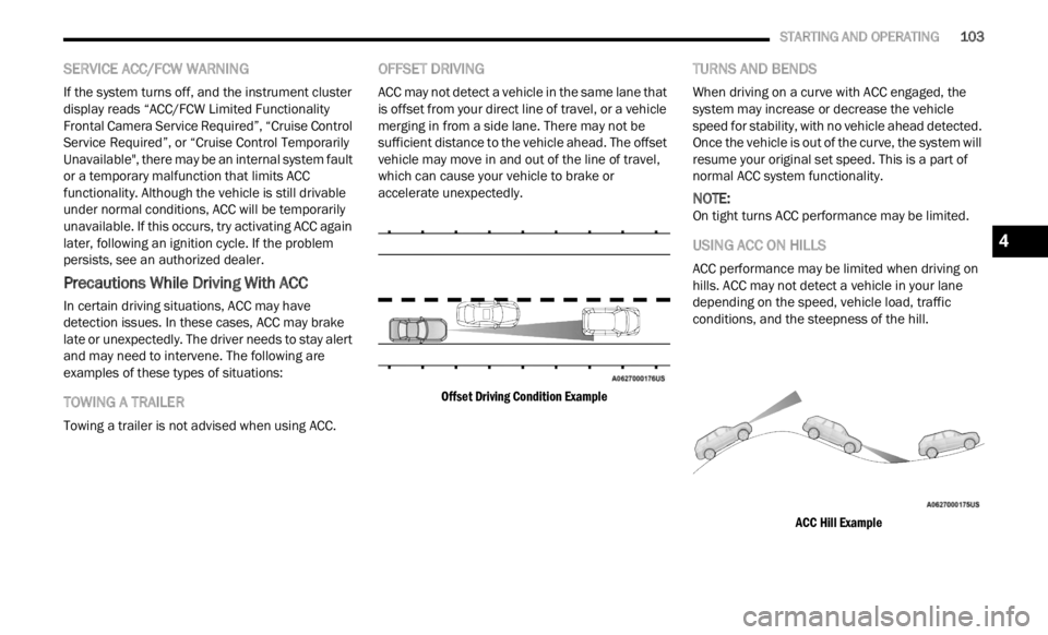
OFFSET DRIVING
ACC may not detect a vehicle in the same lane that
is offset from your direct line of travel, or a vehicle
merging in from a side lane. There may not be
sufficient distance to the vehicle ahead. The offset
vehicle may move in and out of the line of travel,
which can cause your vehicle to brake or
accelerate unexpectedly.
Offset Driving Condition Example
TURNS AND BENDS
When driving on a curve with ACC engaged, the
system may increase or decrease the vehicle
speed for stability, with no vehicle ahead detected.
Once the vehicle is out of the curve, the system will
resume your original set speed. This is a part of
normal ACC system functionality.
NOTE:
On tight turns ACC performance may be limited.
USING ACC ON HILLS
ACC performance may be limited when driving on
hills. ACC may not detect a vehicle in your lane
depending on the speed, vehicle load, traffic
conditions, and the steepness of the hill.
ACC Hill Example
4
Page 111 of 364
STARTING AND OPERATING 109
Clean the ParkSense sensors regularly, taking
care not to scratch or damage them. The
sensors must not be covered with ice, snow,
slush, mud, dirt or debris. Failure to do so can
result in the system not working properly. The
ParkSense system might not detect an obstacle
behind or in front of the fascia/bumper, or it
could provide a false indication that an obstacle
is behind or in front of the fascia/bumper.
Use the ParkSense switch to turn the ParkSense
system off if objects such as bicycle carriers,
etc. are placed within 12
inches (30 cm) from
the re
ar fascia/bumper. Failure to do so can
result in the system misinterpreting a close
object as a sensor problem, causing the “PARK -
SENSE UNAVAILABLE SERVICE REQUIRED”
m essag
e to be displayed in the instrument
cluster display.
NOTE:
If any objects are attached to the bumper within a
6.5 ft
(2 m) field of view, they will interfere and
cause
false alerts and possibly blockage.
There may be a delay in the object detection
rate if the object is moving.
The operation of the rear sensors is automati -
cally deactivated when the trailer's electric plug
is in s
erted in the vehicle's tow hook socket,
while the front sensors stay active and can provide acoustic and visual warnings. The rear
sensors are automatically reactivated when the
trailer's cable plug is removed.
SIDE DISTANCE WARNING (SDW)
S
YSTEM
The Side Distance Warning system has the
function of detecting the presence of side
obstacles near the vehicle using the parking
sensors located in the front and rear bumpers.
Side Distance Warning Display
The Side Distance Warning screen will only be
displayed if “Sound and Display” is selected from
the Customer-Programmable Features section of
the Uconnect system Ú page 133.
WARNING!
Drivers must be careful when backing up even
when using ParkSense. Always check carefully
behind your vehicle, look behind you, and be
sure to check for pedestrians, animals, other
vehicles, obstructions, and blind spots before
backing up. You are responsible for safety and
must continue to pay attention to your
surroundings. Failure to do so can result in
serious injury or death.
Before using ParkSense, it is strongly recom -
mended that the ball mount and hitch ball
assem b
ly be disconnected from the vehicle
when the vehicle is not used for towing.
Failure to do so can result in injury or damage
to vehicles or obstacles because the hitch ball
will be much closer to the obstacle than the
rear fascia when the vehicle sounds the
continuous tone. Also, the sensors could
detect the ball mount and hitch ball assembly,
depending on its size and shape, giving a false
indication that an obstacle is behind the
vehicle.
CAUTION!
ParkSense is only a parking aid and it is
unable to recognize every obstacle, including
small obstacles. Parking curbs might be
temporarily detected or not detected at all.
Obstacles located above or below the sensors
will not be detected when they are in close
proximity.
The vehicle must be driven slowly when using
ParkSense in order to be able to stop in time
when an obstacle is detected. It is recom -
mended that the driver looks over his/her
should e
r when using ParkSense.
4
Page 112 of 364

110 STARTING AND OPERATING
The system warns the driver with an acoustic
signal and where provided, with visual indications
on the instrument panel display.
NOTE:
Parksense will reduce the volume of the radio if
on when the system is sounding an audible
tone.
The alert chime is activated only when the
obstacle is in the vehicle path.
Activation — Deactivation
The system can operate only after driving a short
distance and if the vehicle speed is between 0 and
11
mph (0 and 18 km/h). The system can be
activa
ted/deactivated via the "Settings" menu of
the Uconnect system. If the ParkSense System is
deactivated via the ParkSense Hard switch then
the Side Distance Warning system will
automatically be deactivated.
Message on the display for Side Distance Warning
featu r
e:
“Wipe Sensors” — This message is displayed in the
case o
f a failure of the Side Distance Warning
system sensors. Free the bumpers of any
obstacles, ensure that the front and rear bumper
are free of snow, ice, mud, dirt and debris to keep
the ParkSense system operating properly.
“SDW Not Available” — This message is displayed
if the
Side Distance Warning system is not
available. The failed operation of the system might
be due to the insufficient voltage from the battery
or other failures on the electrical system. Contact
an authorized dealer as soon as possible to have
the electrical system checked.
Operation With A Trailer
The system is automatically deactivated when the
trailer's electric plug is inserted in the vehicle's tow
hook socket. The rear sensors are automatically
reactivated when the trailer's cable plug is
removed.
ParkSense Usage Precautions
Some conditions may influence the performance
of the Side Distance Warning system:
NOTE:
Ensure that the front and rear bumper are free
of snow, ice, mud, dirt and debris to keep the
ParkSense system operating properly.
Construction equipment, large trucks, and other
vibrations could affect the performance of Park -
Sense.
When you turn ParkSense off, the message to
appear in the instrument cluster display will
read “PARKSENSE OFF.” Furthermore, once you
turn ParkSense off, it remains off until you turn
it on again, even if you cycle the ignition key.
ParkSense, when on, will reduce the volume of
the radio when it is sounding a tone.
WARNING ALERTS
Distance
(inches/cm) Less than
12 inc h
es
( 3 0
c
m
) 12–65
inches
(30–6 0
cm)
Arcs-Left 11th Flashing 12th Flashing
Arcs-Right 11th Flashing 12th Flashing
Audible Alert Chime C
on
tinuousAudible chime
incre
a
ses as
the objects within the
vehicle’s path get close to the vehicle
Radio Volume Reduc e
d Yes
Yes
Page 113 of 364
STARTING AND OPERATING 111
Clean the ParkSense sensors regularly, taking
care not to scratch or damage them. The
sensors must not be covered with ice, snow,
slush, mud, dirt or debris. Failure to do so can
result in the system not working properly. The
ParkSense system might not detect an obstacle
behind or in front of the fascia/bumper, or it
could provide a false indication that an obstacle
is behind or in front of the fascia/bumper.
The presence of a tow hook without a trailer may
interfere with the correct operation of the
parking sensors. Before using the ParkSense
system, it is recommended to remove the
removable tow hook ball assembly and any
attachments from the vehicle when it is not
used for towing operations. If you wish to leave
the tow hook fitted when not towing a trailer,
contact your authorized dealer for the Park
-
Sense system operations update because the
tow hook
could be detected as an obstacle by
the sensors.
PARKSENSE ACTIVE PARK ASSIST SYSTEM —
IF EQUIPPED
The ParkSense Active Park Assist system is
intended to assist the driver during parallel,
perpendicular, and parallel park exit maneuvers by
identifying a proper parking space, providing
audible/visual instructions, and controlling the
steering wheel. The ParkSense Active Park Assist
system is defined as “semi-automatic” since the
driver maintains control of the accelerator, gear
selector and brakes. Depending on the driver's
parking maneuver selection, the ParkSense Active
Park Assist system is capable of maneuvering a
WARNING!
Drivers must be careful when backing up even
when using ParkSense. Always check carefully
behind your vehicle, look behind you, and be
sure to check for pedestrians, animals, other
vehicles, obstructions, and blind spots before
backing up. You are responsible for safety and
must continue to pay attention to your
surroundings. Failure to do so can result in
serious injury or death.
Before using ParkSense, it is strongly recom -
mended that the ball mount and hitch ball
assem b
ly be disconnected from the vehicle
when the vehicle is not used for towing.
Failure to do so can result in injury or damage
to vehicles or obstacles because the hitch ball
will be much closer to the obstacle than the
rear fascia when the vehicle sounds the
continuous tone. Also, the sensors could
detect the ball mount and hitch ball assembly,
depending on its size and shape, giving a false
indication that an obstacle is behind the
vehicle.
CAUTION!
ParkSense is only a parking aid and it is
unable to recognize every obstacle, including
small obstacles. Parking curbs might be
temporarily detected or not detected at all.
Obstacles located above or below the sensors
will not be detected when they are in close
proximity.
The vehicle must be driven slowly when using
ParkSense in order to be able to stop in time
when an obstacle is detected. It is recom -
mended that the driver looks over his/her
should e
r when using ParkSense.
4
Page 117 of 364
STARTING AND OPERATING 115
(Continued)
EXITING THE PARKING SPACE
NOTE:
The function does not work for exiting a perpen -
dicular parking space, but only exiting parallel
p arki n
g spaces.
Activation
To activate this function, push the ParkSense
Activ e
Park Assist switch and then use the steering
wheel arrow buttons to select the Parallel Park Exit
feature. After the selection, the system activates
and instructs the driver through the instrument
cluster display about the operations that have to
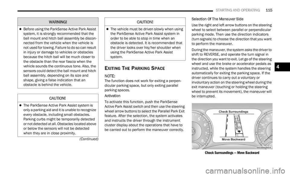
be carried out to perform the maneuver correctly. Selection Of The Maneuver Side
Use the right and left arrow buttons on the steering
wheel
to select between parallel or perpendicular
parking mode. Then use the direction indicators
(turn signals) to choose the direction that you want
to perform the maneuver.
During the maneuver, the system asks the driver to
shift
to REVERSE, and operate the turn signal in
the direction you want to exit. Let go of the steering
wheel and use the brake or accelerator pedals as
instructed, while the system handles the steering
automatically for exiting the parking space. If the
driver continues to carry out a voluntary or
involuntary action on the steering wheel during the
exit maneuver (touching or holding the steering
wheel to prevent its movement), the maneuver will
be interrupted.
Check Surroundings — Move Backward
Before using the ParkSense Active Park Assist
system, it is strongly recommended that the
ball mount and hitch ball assembly be discon -
nected from the vehicle when the vehicle is
not us e
d for towing. Failure to do so can result
in injury or damage to vehicles or obstacles
because the hitch ball will be much closer to
the obstacle than the rear fascia when the
vehicle sounds the continuous tone. Also, the
sensors could detect the ball mount and hitch
ball assembly, depending on its size and
shape, giving a false indication that an
obstacle is behind the vehicle.
CAUTION!
The ParkSense Active Park Assist system is
only a parking aid and it is unable to recognize
every obstacle, including small obstacles.
Parking curbs might be temporarily detected
or not detected at all. Obstacles located above
or below the sensors will not be detected
when they are in close proximity.
WARNING!
The vehicle must be driven slowly when using
the ParkSense Active Park Assist system in
order to be able to stop in time when an
obstacle is detected. It is recommended that
the driver looks over his/her shoulder when
using the ParkSense Active Park Assist
system.
CAUTION!
4
Page 118 of 364
116 STARTING AND OPERATING
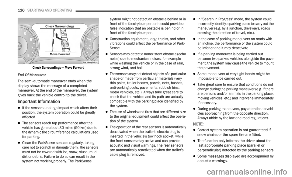
Check Surroundings — Move Forward
End Of Maneuver
The semi-automatic maneuver ends when the
displ a
y shows the message of a completed
maneuver. At the end of the maneuver, the system
gives back the vehicle control to the driver.
Important Information
If the sensors undergo impact which alters their
position, the system operation could be greatly
affected.
The sensors reach top performance after the
vehicle has gone about 30 miles (50 km) due to
the d y
namic tire circumference calculations used
for parking.
Clean the ParkSense sensors regularly, taking
care not to scratch or damage them. The sensors
must not be covered with ice, snow, slush, mud,
dirt or debris. Failure to do so can result in the
system not working properly. The ParkSense system might not detect an obstacle behind or in
front of the fascia/bumper, or it could provide a
false indication that an obstacle is behind or in
front of the fascia/bumper.
Construction equipment, large trucks, and other
vibrations could affect the performance of Park
-
Sense.
Sensors may detect a nonexistent obstacle (echo
noise) due to mechanical noises, for example
while washing the vehicle or in the case of rain,
strong wind, and hail.
The sensors may not detect objects of a particular
shape or made from particular materials (very
thin poles, trailer beams, panels, nets, bushes,
anti-parking posts, pavements, rubbish bins,
motor vehicles, etc.). Always take great care to
check that the vehicle and its path are actually
compatible with the parking place identified by
the system.
The use of wheels and tires that are different size
to the original equipment could affect the opera -
tion of the system.
The operation of the rear sensors is automatically
deactivated when the trailer's electric plug is
inserted in the vehicle's tow hook socket, while
the front sensors stay active and can provide
acoustic and visual warnings. The rear sensors
are automatically reactivated when the trailer's
cable plug is removed.
In "Search in Progress" mode, the system could
incorrectly identify a parking place to carry out the
maneuver (e.g. by a junction, driveways, roads
crossing the direction of travel, etc.).
In the case of parking maneuvers on roads with
an incline, the performance of the system could
be inferior and it may deactivate.
If a parking maneuver is being carried out
between two parked vehicles alongside the pave -
ment, the system may cause the vehicle to mount
t he pa
vement.
Some maneuvers at very tight bends might be
impossible to be carried out.
Take great care to ensure that conditions do not
change during the parking maneuver (e.g. if there
are persons and/or animals in the parking place,
moving vehicles, etc.) and intervene immediately
if necessary.
During parking maneuvers, pay attention to vehi -
cles approaching from the opposite direction.
Alway s
abide by the law and road regulations.
NOTE:
Correct system operation is not guaranteed if
snow chains or the spare tire are fitted.
The function only informs the driver about the
last appropriate parking place (parallel or
perpendicular) detected by the parking sensors.
Some messages displayed are accompanied by
acoustic warnings.
Page 125 of 364

STARTING AND OPERATING 123
VEHICLE LOADING
CERTIFICATION LABEL
As required by National Highway Traffic Safety
Administration regulations, your vehicle has a
certification label affixed to the driver's side door or
pillar
Ú page 322.
This label contains the month and year of
m anufa
cture, Gross Vehicle Weight Rating
(GVWR), Gross Axle Weight Rating (GAWR) front
and rear, and Vehicle Identification Number (VIN).
A Month-Day-Hour (MDH) number is included on
this label and indicates the Month, Day and Hour of
manufacture. The bar code that appears on the
bottom of the label is your VIN.
Gross Vehicle Weight Rating (GVWR)
The GVWR is the total permissible weight of your
vehicle including driver, passengers, vehicle,
options and cargo. The label also specifies
maximum capacities of front and rear axle systems
(GAWR). Total load must be limited so GVWR and
front and rear GAWR are not exceeded.
Payload
The payload of a vehicle is defined as the allowable
load weight a truck can carry, including the weight
of the driver, all passengers, options and cargo.
Gross Axle Weight Rating (GAWR)
The GAWR is the maximum permissible load on the
front and rear axles. The load must be distributed
in the cargo area so that the GAWR of each axle is
not exceeded.
Each axle GAWR is determined by the components
in the
system with the lowest load carrying capacity
(axle, springs, tires or wheels). Heavier axles or
suspension components sometimes specified by
purchasers for increased durability does not
necessarily increase the vehicle's GVWR.
Tire Size
The tire size on the Vehicle Certification Label
represents the actual tire size on your vehicle.
Replacement tires must be equal to the load
capacity of this tire size.
Rim Size
This is the rim size that is appropriate for the tire
size listed.
Inflation Pressure
This is the cold tire inflation pressure for your
vehicle for all loading conditions up to full GAWR.
Curb Weight
The curb weight of a vehicle is defined as the total
weight of the vehicle with all fluids, including
vehicle fuel, at full capacity conditions, and with no
occupants or cargo loaded into the vehicle. The
front and rear curb weight values are determined
by weighing your vehicle on a commercial scale
before any occupants or cargo are added.
Loading
The actual total weight and the weight of the front
and rear of your vehicle at the ground can best be
determined by weighing it when it is loaded and
ready for operation.
The entire vehicle should first be weighed on a
commerc
ial scale to ensure that the GVWR has not
been exceeded. The weight on the front and rear of
the vehicle should then be determined separately
to be sure that the load is properly distributed over
the front and rear axle. Weighing the vehicle may
show that the GAWR of either the front or rear axles
has been exceeded but the total load is within the
specified GVWR. If so, weight must be shifted from
front to rear or rear to front as appropriate until the
specified weight limitations are met. Store the
heavier items down low and be sure that the
weight is distributed equally. Stow all loose items
securely before driving.
4