tow JEEP RENEGADE 2023 User Guide
[x] Cancel search | Manufacturer: JEEP, Model Year: 2023, Model line: RENEGADE, Model: JEEP RENEGADE 2023Pages: 364, PDF Size: 18.65 MB
Page 48 of 364
46 GETTING TO KNOW YOUR VEHICLE
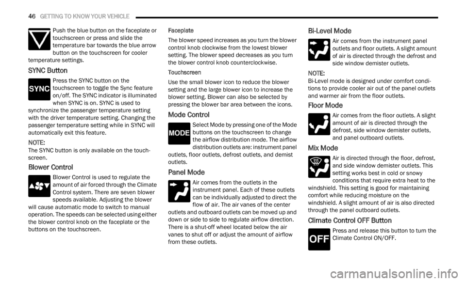
Push the blue button on the faceplate or
touchscreen or press and slide the
tempe r
ature bar towards the blue arrow
button on the touchscreen for cooler
temperature settings.
SYNC Button
Press the SYNC button on the
touchscreen to toggle the Sync feature
on/off.
The SYNC indicator is illuminated
when SYNC is on. SYNC is used to
synchronize the passenger temperature setting
with the driver temperature setting. Changing the
passenger temperature setting while in SYNC will
automatically exit this feature.
NOTE:
The SYNC button is only available on the touch-
screen.
Blower Control
Blower Control is used to regulate the
amount of air forced through the Climate
Control
system. There are seven blower
speeds available. Adjusting the blower
will cause automatic mode to switch to manual
operation. The speeds can be selected using either
the blower control knob on the faceplate or the
buttons on the touchscreen. Faceplate
The blower speed increases as you turn the blower
c
ontrol
knob clockwise from the lowest blower
setting. The blower speed decreases as you turn
the blower control knob counterclockwise.
Touchscreen
Use the small blower icon to reduce the blower
setti n
g and the large blower icon to increase the
blower setting. Blower can also be selected by
pressing the blower bar area between the icons.
Mode Control
Select Mode by pressing one of the Mode
buttons on the touchscreen to change
the a i
rflow distribution mode. The airflow
distribution outlets are: instrument panel
outlets, floor outlets, defrost outlets, and demist
outlets.
Panel Mode
Air comes from the outlets in the
instrument panel. Each of these outlets
can b e
individually adjusted to direct the
flow of air. The air vanes of the center
outlets and outboard outlets can be moved up and
down or side to side to regulate airflow direction.
There is a shut-off wheel located below the air
vanes to shut off or adjust the amount of airflow
from these outlets.
Bi-Level Mode
Air comes from the instrument panel
outlets and floor outlets. A slight amount
of ai r
is directed through the defrost and
side window demister outlets.
NOTE:
Bi-Level mode is designed under comfort condi -
tions to provide cooler air out of the panel outlets
a nd w a
rmer air from the floor outlets.
Floor Mode
Air comes from the floor outlets. A slight
amount of air is directed through the
defrost
, side window demister outlets,
and panel outboard outlets.
Mix Mode
Air is directed through the floor, defrost,
and side window demister outlets. This
setti n
g works best in cold or snowy
conditions that require extra heat to the
windshield. This setting is good for maintaining
comfort while reducing moisture on the
windshield. A slight amount of air is also directed
through the panel outboard outlets.
Climate Control OFF Button
Press and release this button to turn the
Climate Control ON/OFF.
Page 58 of 364
56 GETTING TO KNOW YOUR VEHICLE
SUNROOF MAINTENANCE
Use only a non-abrasive cleaner and a soft cloth to
clean the glass panel. Periodically check for and
clear out any debris that may have collected in the
tracks.
HOOD
TO OPEN THE HOOD
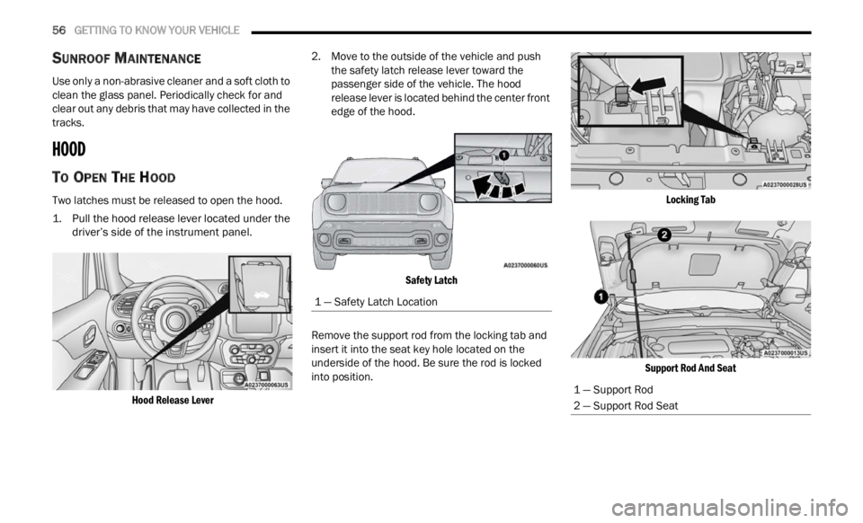
Two latches must be released to open the hood.
1. Pull the hood release lever located under the
driver’ s
side of the instrument panel.
Hood Release Lever
2. Move to the outside of the vehicle and push
the s
afety latch release lever toward the
passenger side of the vehicle. The hood
release lever is located behind the center front
edge of the hood.
Safety Latch
Remove the support rod from the locking tab and
inser t
it into the seat key hole located on the
underside of the hood. Be sure the rod is locked
into position.
Locking Tab
Support Rod And Seat
1 — Safety Latch Location
1 — Support Rod
2 — Support Rod Seat
Page 61 of 364
GETTING TO KNOW YOUR VEHICLE 59
Position 1 (Lowered Position):
This position allows you to make the load floor flat
for ea s
e of loading/unloading objects from the
cargo area. This position also makes it possible to
use the space below as another compartment for
storing fragile or smaller objects.
Position 2 (Elevated Position):
When the rear seatbacks and front passenger seat
a re f ol
ded flat, it creates space for objects of long
dimensions. This position is recommended only
when transporting objects, then move the load
floor back to position 1.
Table Tilt Load
In addition to the two positions described
p reviou
sly, the load floor can also be placed in a
tilted position, slanted toward the rear seatbacks
as to ease the access to the underlying zone of the
luggage compartment (e.g. to pick up the spare tire
or the Tire Service Kit).
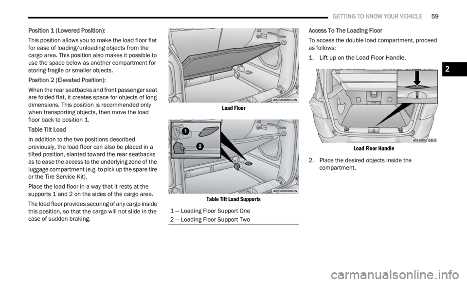
Place the load floor in a way that it rests at the
suppor t
s 1 and 2 on the sides of the cargo area.
The load floor provides securing of any cargo inside
this p
osition, so that the cargo will not slide in the
case of sudden braking.
Load Floor
Table Tilt Load Supports
Access To The Loading Floor
To access the double load compartment, proceed
as fol
l
ows:
1. Lift up on the Load Floor Handle.
Load
Floor Handle
2. Place the desired objects inside the compar
tment.
1 — Loading Floor Support One
2 — Loading Floor Support Two
2
Page 73 of 364
GETTING TO KNOW YOUR INSTRUMENT PANEL 71
Door Open Warning Light
This indicator will illuminate when a door
is ajar/open and not fully closed. The
light
will show which doors are currently
ajar/open.
NOTE:
If the vehicle is moving, there will also be a single
chime .
Electric Power Steering Fault Warning
Light
This warning light will turn on when
there's a fault with the Electric Power
Steeri
ng (EPS) system Ú page 93.
Electronic Throttle Control (ETC) Warning
Light
This light informs you of a problem with
the ETC system. If a problem is detected
w
hi
l e
the vehicle is running, the light will
either stay on or flash depending on the
nature of the problem. Cycle the ignition when the
vehicle is safely and completely stopped and the transmission is placed in the PARK position. The
light should turn off. If the light remains on with the
vehicle running, your vehicle will usually be
drivable; however, see an authorized dealer for
service as soon as possible.
NOTE:
This light may turn on if the accelerator and brake
pedal s
are pressed at the same time.
If the light continues to flash when the vehicle is
runnin
g, immediate service is required and you
may experience reduced performance, an
elevated/rough idle, or engine stall and your
vehicle may require towing. The light will come on
when the ignition is placed in the ON/RUN or ACC/
ON/RUN position and remain on briefly as a bulb
check. If the light does not come on during starting,
have the system checked by an authorized dealer.
Engine Coolant Temperature Warning
Light
This warning light will illuminate to warn
of an overheated engine condition. If the
e n g
in
e
coolant temperature is too high,
this light will illuminate and a single
chime will sound.
If the light turns on while driving, safely pull over
and st
op the vehicle. If the Air Conditioning (A/C)
system is on, turn it off. Also, shift the transmission
into NEUTRAL and idle the vehicle. If the
temperature reading does not return to normal, turn the engine off immediately and call for service
Ú page 281.
Hood Open Warning Light
This warning light will illuminate when the
hood is left open and not fully closed.
NOTE:
If the vehicle is moving, there will also be a single
chime .
Liftgate Open Warning Light
This indicator will illuminate when the
liftgate is left open and not fully closed.
NOTE:
If the vehicle is moving, there will also be a single
chime .
Oil Pressure Warning Light
This warning light will illuminate to
indicate low engine oil pressure. If the
light
turns on while driving, stop the
vehicle, shut off the engine as soon as
possible, and contact an authorized dealer. A
chime will sound when this light turns on.
Do not operate the vehicle until the cause is
correc t
ed. This light does not indicate how much oil
is in the engine. The engine oil level must be
checked under the hood.
WARNING!
Continued operation with reduced assist could
pose a safety risk to yourself and others. Service
should be obtained as soon as possible.
3
Page 75 of 364
GETTING TO KNOW YOUR INSTRUMENT PANEL 73
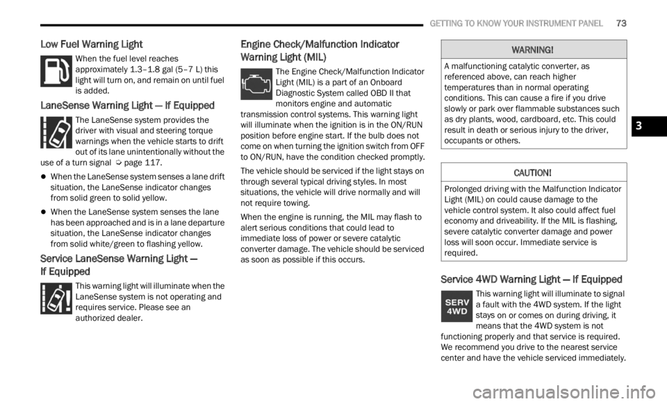
Low Fuel Warning Light
When the fuel level reaches
approximately 1.3–1.8 gal (5–7 L) this
light
will turn on, and remain on until fuel
is added.
LaneSense Warning Light — If Equipped
The LaneSense system provides the
driver with visual and steering torque
warni n
gs when the vehicle starts to drift
out of its lane unintentionally without the
use of a turn signal Ú page 117.
When the LaneSense system senses a lane drift
situation, the LaneSense indicator changes
from solid green to solid yellow.
When the LaneSense system senses the lane
has been approached and is in a lane departure
situation, the LaneSense indicator changes
from solid white/green to flashing yellow.
Service LaneSense Warning Light —
If Equipped
This warning light will illuminate when the
LaneSense system is not operating and
r e q
ui
r
es service. Please see an
authorized dealer.
Engine Check/Malfunction Indicator
Warning Light (MIL)
The Engine Check/Malfunction Indicator
Light (MIL) is a part of an Onboard
D ia
gn
os
tic System called OBD II that
monitors engine and automatic
transmission control systems. This warning light
will illuminate when the ignition is in the ON/RUN
position before engine start. If the bulb does not
come on when turning the ignition switch from OFF
to ON/RUN, have the condition checked promptly.
The vehicle should be serviced if the light stays on
throug h
several typical driving styles. In most
situations, the vehicle will drive normally and will
not require towing.
When the engine is running, the MIL may flash to
alert
serious conditions that could lead to
immediate loss of power or severe catalytic
converter damage. The vehicle should be serviced
as soon as possible if this occurs.
Service 4WD Warning Light — If Equipped
This warning light will illuminate to signal
a fault with the 4WD system. If the light
stays
on or comes on during driving, it
means that the 4WD system is not
functioning properly and that service is required.
We recommend you drive to the nearest service
center and have the vehicle serviced immediately.
WARNING!
A malfunctioning catalytic converter, as
referenced above, can reach higher
temperatures than in normal operating
conditions. This can cause a fire if you drive
slowly or park over flammable substances such
as dry plants, wood, cardboard, etc. This could
result in death or serious injury to the driver,
occupants or others.
CAUTION!
Prolonged driving with the Malfunction Indicator
Light (MIL) on could cause damage to the
vehicle control system. It also could affect fuel
economy and driveability. If the MIL is flashing,
severe catalytic converter damage and power
loss will soon occur. Immediate service is
required.
3
Page 77 of 364
GETTING TO KNOW YOUR INSTRUMENT PANEL 75
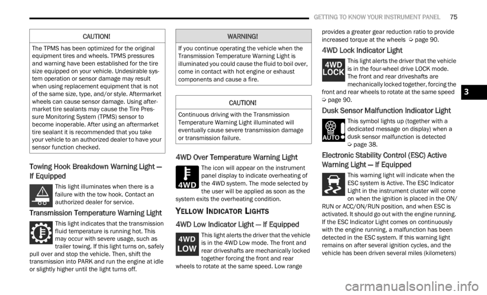
Towing Hook Breakdown Warning Light —
If Equipped
This light illuminates when there is a
failure with the tow hook. Contact an
a ut
h or
i
zed dealer for service.
Transmission Temperature Warning Light
This light indicates that the transmission
fluid temperature is running hot. This
may occ
ur with severe usage, such as
trailer towing. If this light turns on, safely
pull over and stop the vehicle. Then, shift the
transmission into PARK and run the engine at idle
or slightly higher until the light turns off.
4WD Over Temperature Warning Light
The icon will appear on the instrument
panel display to indicate overheating of
t h e
4
W
D system. The mode selected by
the user will be applied as soon as the
system exits the overheating condition.
YELLOW INDICATOR LIGHTS
4WD Low Indicator Light — If Equipped
This light alerts the driver that the vehicle
is in the 4WD Low mode. The front and
rear d
riveshafts are mechanically locked
together forcing the front and rear
wheels to rotate at the same speed. Low range provides a greater gear reduction ratio to provide
increased torque at the wheels
Ú page 90.
4WD Lock Indicator Light
This light alerts the driver that the vehicle
is in the four-wheel drive LOCK mode.
The f r
ont and rear driveshafts are
mechanically locked together, forcing the
front and rear wheels to rotate at the same speed
Ú page 90.
Dusk Sensor Malfunction Indicator Light
This symbol lights up (together with a
dedicated message on display) when a
dusk s
ensor malfunction is detected
Ú page 38.
Electronic Stability Control (ESC) Active
Warning Light — If Equipped
This warning light will indicate when the
ESC system is Active. The ESC Indicator
Light
in the instrument cluster will come
on when the ignition is placed in the ON/
RUN or ACC/ON/RUN position, and when ESC is
activated. It should go out with the engine running.
If the ESC Indicator Light comes on continuously
with the engine running, a malfunction has been
detected in the ESC system. If this warning light
remains on after several ignition cycles, and the
vehicle has been driven several miles (kilometers)
CAUTION!
The TPMS has been optimized for the original
equipment tires and wheels. TPMS pressures
and warning have been established for the tire
size equipped on your vehicle. Undesirable sys -
tem operation or sensor damage may result
w hen u
sing replacement equipment that is not
of the same size, type, and/or style. Aftermarket
wheels can cause sensor damage. Using after -
market tire sealants may cause the Tire Pres -
sure Monitoring System (TPMS) sensor to
b ecome
inoperable. After using an aftermarket
tire sealant it is recommended that you take
your vehicle to an authorized dealer to have your
sensor function checked.
WARNING!
If you continue operating the vehicle when the
Transmission Temperature Warning Light is
illuminated you could cause the fluid to boil over,
come in contact with hot engine or exhaust
components and cause a fire.
CAUTION!
Continuous driving with the Transmission
Temperature Warning Light illuminated will
eventually cause severe transmission damage
or transmission failure.
3
Page 79 of 364
GETTING TO KNOW YOUR INSTRUMENT PANEL 77
will flash. Turn signals can be activated when the
multifunction lever is moved down (left) or up
(right).
WHITE INDICATOR LIGHTS
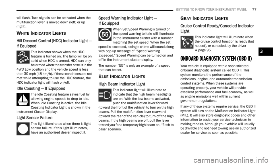
Hill Descent Control (HDC) Indicator Light —
If Equipped
This indicator shows when the HDC
feature is turned on. The lamp will be on
solid w
hen HDC is armed. HDC can only
be armed when the transfer case is in the
4WD Low position and the vehicle speed is less
then 30 mph (48 km/h). If these conditions are not
met wh
ile attempting to use the HDC feature, the
HDC indicator light will flash on/off.
Idle Coasting — If Equipped
The Idle Coasting feature saves fuel by
allowing engine speeds to drop to idle.
W he
n
I
dle Coasting is active, the Idle
Coasting Indicator Light is shown in the
Instrument Cluster Display.
Light Sensor Failure
This light illuminates when there is light
sensor failure. If this light illuminates,
have a
n authorized dealer inspect it.
Speed Warning Indicator Light —
If Equipped
When Set Speed Warning is turned on,
the speed warning telltale will illuminate
i n
t h
e
instrument cluster with a number
matching the set speed. When the set
speed is exceeded, a single chime will sound along
with pop-up message of “Speed Warning
Exceeded.” Speed Warning can be turned on and
off in the instrument cluster display.
The number “55” is only an example of a speed
that c
an be set.
BLUE INDICATOR LIGHTS
High Beam Indicator Light
This indicator light will illuminate to
indicate that the high beam headlights
are on .
With the low beams activated,
push the multifunction lever forward
(toward the front of the vehicle) to turn on the high
beams. Pull the multifunction lever rearward
(toward the rear of the vehicle) to turn off the high
beams. If the high beams are off, pull the lever
toward you for a temporary high beam on, “flash to
pass” scenario.
GRAY INDICATOR LIGHTS
Cruise Control Ready/Canceled Indicator
Light
This indicator light will illuminate when
the cruise control function is ready (but
not se t
), or canceled, by the driver
Ú page 95.
ONBOARD DIAGNOSTIC SYSTEM (OBD II)
Your vehicle is equipped with a sophisticated
onboard diagnostic system called OBD II. This
system monitors the performance of the
emissions, engine, and automatic transmission
control systems. When these systems are
operating properly, your vehicle will provide
excellent performance and fuel economy, as well
as engine emissions well within current
government regulations.
If any of these systems require service, the OBD II
syste m
will turn on the Malfunction Indicator Light
(MIL). It will also store diagnostic codes and other
information to assist your service technician in
making repairs. Although your vehicle will usually
be drivable and not need towing, see an authorized
dealer for service as soon as possible.
3
Page 83 of 364
STARTING AND OPERATING 81
COLD WEATHER OPERATION
To ensure reliable starting under extreme cold
conditions an externally powered electric block
heater (if equipped) is required for the 1.3L Turbo
engine below -20°F (-29°C). To prevent possible engine damage while starting
at low
temperatures, this vehicle will inhibit engine
cranking when the ambient temperature is less
than -20°F (-29°C) for the 1.3L Turbo engine, and
the oil temperature sensor reading indicates an
engine block heater has not been used. The
message “plug in engine heater” will be displayed
in the instrument cluster when the ambient
temperature is below -4°F (-20°C) at the time the
engine is shut off as a reminder to avoid possible
crank delays at the next cold start.
EXTENDED PARK STARTING
NOTE:
Extended Park condition occurs when the vehicle
has n ot
been started or driven for at least 30 days.
1. Install a battery charger or jumper cables to the ba
ttery to ensure a full battery charge
during the crank cycle.
2. Press the START/STOP ignition button and relea
se it when the engine starts.
3. If the engine fails to start within 10 seconds, place
the ignition in the OFF position, wait
10 to 15 seconds to allow the starter to cool,
t hen r
epeat the Extended Park Starting
procedure.
4. If the engine fails to start after eight attempts, allow
the starter to cool for at least
10 minutes, then repeat the procedure.
AFTER STARTING — WARMING UP THE
E
NGINE
Proceed as follows:
Travel slowly, letting the engine run at a reduced
RPM, without accelerating suddenly.
It is recommended to wait until the engine
coolant temperature gauge starts to rise for
maximum performance.
STOPPING THE ENGINE
To shut off the engine with a vehicle speed greater
than 5 mph (8 km/h), you must push and hold the
ignit i
on or push the START/STOP button three
times consecutively within a few seconds. The
engine will shut down, and the ignition will be
placed in the RUN position.
Vehicles Equipped With Electronic Key
(Keyless Enter ‘n Go™)
Turning off the car (cycle the ignition from the RUN
p ositi on
to the OFF position), the power supply to
the accessories are maintained for a period of
three minutes.
Do not attempt to push or tow your vehicle to
get it started. Vehicles equipped with an auto -
matic transmission cannot be started this
w ay. U
nburned fuel could enter the catalytic
converter and once the engine has started,
ignite and damage the converter and vehicle.
If the vehicle has a discharged battery,
booster cables may be used to obtain a start
from a booster battery or the battery in
another vehicle. This type of start can be
dangerous if done improperly Ú page 278.
CAUTION!
To prevent damage to the starter, do not
continuously crank the engine for more than
10 seconds at a time. Wait 10 to 15 seconds
before
trying again.
WARNING!CAUTION!
To prevent damage to the starter, do not crank
continuously for more than 10 seconds at a
time. Wait 10 to 15 seconds before trying again.
4
Page 85 of 364
STARTING AND OPERATING 83
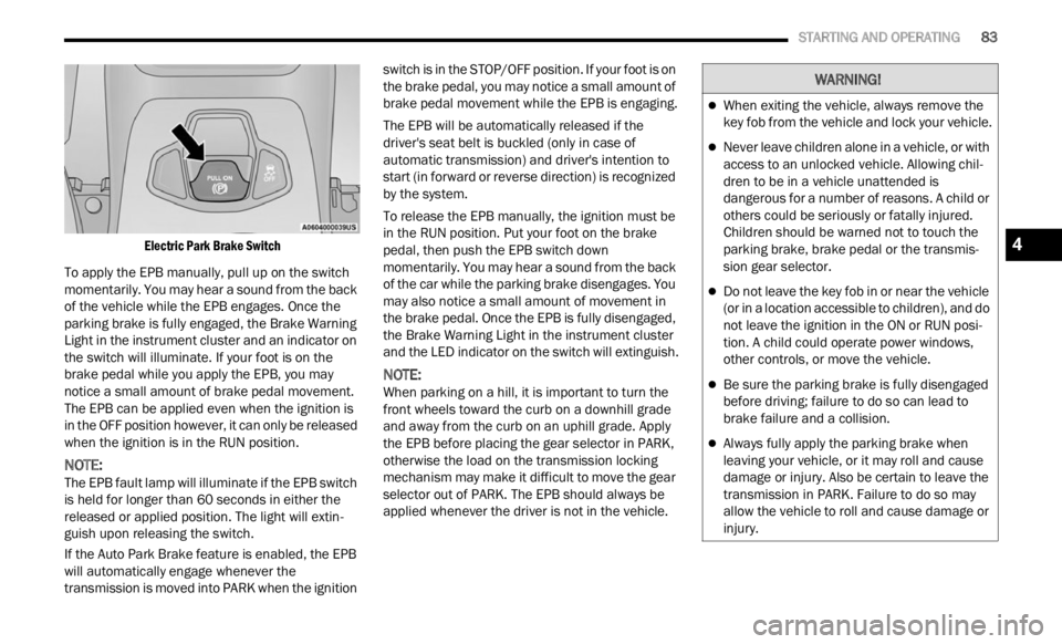
Electric Park Brake Switch
To apply the EPB manually, pull up on the switch
momenta
rily. You may hear a sound from the back
of the vehicle while the EPB engages. Once the
parking brake is fully engaged, the Brake Warning
Light in the instrument cluster and an indicator on
the switch will illuminate. If your foot is on the
brake pedal while you apply the EPB, you may
notice a small amount of brake pedal movement.
The EPB can be applied even when the ignition is
in the OFF position however, it can only be released
when the ignition is in the RUN position.
NOTE:
The EPB fault lamp will illuminate if the EPB switch
is he l
d for longer than 60 seconds in either the
released or applied position. The light will extin -
guish upon releasing the switch.
If the Auto Park Brake feature is enabled, the EPB
w ill a
utomatically engage whenever the
transmission is moved into PARK when the ignition switch is in the STOP/OFF position. If your foot is on
the brake pedal, you may notice a small amount of
brake pedal movement while the EPB is engaging.
The EPB will be automatically released if the
drive
r
's seat belt is buckled (only in case of
automatic transmission) and driver's intention to
start (in forward or reverse direction) is recognized
by the system.
To release the EPB manually, the ignition must be
in th e
RUN position. Put your foot on the brake
pedal, then push the EPB switch down
momentarily. You may hear a sound from the back
of the car while the parking brake disengages. You
may also notice a small amount of movement in
the brake pedal. Once the EPB is fully disengaged,
the Brake Warning Light in the instrument cluster
and the LED indicator on the switch will extinguish.
NOTE:
When parking on a hill, it is important to turn the
front w
heels toward the curb on a downhill grade
and away from the curb on an uphill grade. Apply
the EPB before placing the gear selector in PARK,
otherwise the load on the transmission locking
mechanism may make it difficult to move the gear
selector out of PARK. The EPB should always be
applied whenever the driver is not in the vehicle.
WARNING!
When exiting the vehicle, always remove the
key fob from the vehicle and lock your vehicle.
Never leave children alone in a vehicle, or with
access to an unlocked vehicle. Allowing chil -
dren to be in a vehicle unattended is
d anger
ous for a number of reasons. A child or
others could be seriously or fatally injured.
Children should be warned not to touch the
parking brake, brake pedal or the transmis -
sion gear selector.
Do not leave the key fob in or near the vehicle
(or in a location accessible to children), and do
not leave the ignition in the ON or RUN posi -
tion. A child could operate power windows,
other c
ontrols, or move the vehicle.
Be sure the parking brake is fully disengaged
before driving; failure to do so can lead to
brake failure and a collision.
Always fully apply the parking brake when
leaving your vehicle, or it may roll and cause
damage or injury. Also be certain to leave the
transmission in PARK. Failure to do so may
allow the vehicle to roll and cause damage or
injury.
4
Page 89 of 364
STARTING AND OPERATING 87
(Continued)
(Continued)
GEAR RANGES
PARK (P)
This range supplements the Electric Park Brake
(
E P
B )
by locking the transmission. The engine can
be started in this range. Never attempt to use
PARK while the vehicle is in motion.
When parking on a hill, apply the EPB before
shifti
ng the transmission to PARK, otherwise the
load on the transmission locking mechanism may
make it difficult to move the gear selector out of
PARK. As an added precaution, turn the front
wheels toward the curb on a downhill grade and
away from the curb on an uphill grade.
When exiting the vehicle, always:
Apply the parking brake.
Shift the transmission into PARK.
Turn the ignition OFF.
Remove the key fob from the vehicle.
CAUTION!
After selecting any gear range, wait a moment to
allow the selected gear to engage before
accelerating. This is especially important when
the engine is cold.
WARNING!
Never use the PARK position as a substitute
for the parking brake. Always apply the
parking brake fully when exiting the vehicle to
guard against vehicle movement and possible
injury or damage.
Your vehicle could move and injure you and
others if it is not in PARK. Check by trying to
move the transmission gear selector out of
PARK with the brake pedal released. Make
sure the transmission is in PARK before
exiting the vehicle.
The transmission may not engage PARK if the
vehicle is moving. Always bring the vehicle to a
complete stop before shifting to PARK, and
verify that the transmission gear position indi -
cator solidly indicates PARK (P) without
b linki
ng. Ensure that the vehicle is completely
stopped, and the PARK position is properly
indicated, before exiting the vehicle.
It is dangerous to shift out of PARK or
NEUTRAL if the engine speed is higher than
idle speed. If your foot is not firmly pressing
the brake pedal, the vehicle could accelerate
quickly forward or in reverse. You could lose
control of the vehicle and hit someone or
something. Only shift into gear when the
engine is idling normally (or stopped) and your
foot is firmly pressing the brake pedal.
Unintended movement of a vehicle could
injure those in or near the vehicle. As with all
vehicles, you should never exit a vehicle while
the engine is running or the propulsion system
is active. Before exiting a vehicle, always come
to a complete stop, then apply the parking
brake, shift the transmission into PARK, and
turn the ignition OFF. When the ignition is in
the OFF position, the transmission is locked in
PARK, securing the vehicle against unwanted
movement.
When leaving the vehicle, always make sure
the ignition is in the OFF position, remove the
key fob from the vehicle, and lock the vehicle.
WARNING!
4