engine JEEP RENEGADE 2023 Service Manual
[x] Cancel search | Manufacturer: JEEP, Model Year: 2023, Model line: RENEGADE, Model: JEEP RENEGADE 2023Pages: 364, PDF Size: 18.65 MB
Page 95 of 364
STARTING AND OPERATING 93
ACTIVE GRILLE SHUTTERS — IF EQUIPPED
Your vehicle may be equipped with Active Grille
Shutters. Active Grille Shutters is an automatic
system with mobile flaps applied in front of the
cooling module that aims to improve vehicle
aerodynamic efficiency with its automatic
opening/closing movement. The opening/closing
movement of the Active Grill Shutters reduces
consumption while ensuring optimal engine
operating temperature conditions.
When a greater air flow is required for cooling (e.g.
when d
riving in urban traffic) the flaps open,
whereas when temperature is low or air flow is
enough (example when driving on highways), the
flaps close.
POWER STEERING
The electric power steering system will provide
increased vehicle response and ease of
maneuverability. The power steering system
adapts to different driving conditions. If the “SERVICE POWER STEERING” OR “POWER
STEER
I
NG ASSIST OFF - SERVICE SYSTEM”
message and a steering wheel icon are displayed
on the instrument cluster screen, it indicates that
the vehicle needs to be taken to the dealer for
service. It is likely the vehicle has lost power
steering assistance Ú page 64.
NOTE:
Even if the power steering assistance is no
longer operational, it is still possible to steer the
vehicle. Under these conditions there will be a
substantial increase in steering effort, espe
-
cially at low speeds and during parking maneu -
vers.
If the condition persists, see an authorized
dealer for service.
STOP/START SYSTEM
The Stop/Start function was developed to reduce
fuel consumption. The system will stop the engine
automatically during a vehicle stop if the required
conditions are met. Releasing the brake pedal or
pressing the accelerator pedal will automatically
restart the engine.
AUTOSTOP MODE
The Stop/Start feature is enabled after every
normal customer engine start. At that time, the
system will go into STOP/START READY and if all
other conditions are met, can go into a STOP/
START AUTOSTOP ACTIVE “Autostop” mode.
To Activate The Autostop Mode, The Following
Must O
ccur:
The system must be in STOP/START READY
state. A STOP/START READY message will be
displayed in the instrument cluster display
within the Stop/Start section Ú page 64.
The vehicle must be completely stopped.
The gear selector must be in a forward gear and
the brake pedal pressed.
The engine will shut down, the tachometer will
move to
the zero position and the Stop/Start
telltale will illuminate indicating you are in
Autostop. Customer settings will be maintained
upon return to an engine running condition.
WARNING!
Continued operation with reduced assist could
pose a safety risk to yourself and others. Service
should be obtained as soon as possible.
4
Page 96 of 364

94 STARTING AND OPERATING
POSSIBLE REASONS THE ENGINE DOES
N
OT AUTOSTOP
Prior to engine shut down, the system will check
many safety and comfort conditions to see if they
are fulfilled. Detailed information about the
operation of the Stop/Start system may be viewed
in the instrument cluster display Stop/Start
Screen. In the following situations the engine will
not stop:
Driver’s seat belt is not buckled.
Driver’s door is not closed.
Battery temperature is too warm or cold.
Battery charge is low.
The vehicle is on a steep grade.
Cabin heating or cooling is in process and an
acceptable cabin temperature has not been
achieved.
HVAC is set to full defrost mode at a high blower
speed.
HVAC is set to MAX A/C.
Engine has not reached normal operating
temperature.
The transmission is not in a forward gear.
Hood is open.
Vehicle is in 4WD LOW transfer case mode (if
equipped with 4WD).
Brake pedal is not pressed with sufficient pres -
sure with vehicle in DRIVE position.
Accelerator pedal input.
Engine temp is too high.
5 mph (8 km/h) threshold not achieved from
previou
s AUTOSTOP.
Steering angle is beyond threshold.
It may be possible for the vehicle to be driven
s e v
e r
a
l times without the Stop/Start system going
into a STOP/START READY state under more
extreme conditions of the items listed above.
TO START THE ENGINE WHILE IN
A
UTOSTOP MODE
While in a forward gear, the engine will start when
the brake pedal is released or the throttle pedal is
pressed. The transmission will automatically
re-engage upon engine restart.
Conditions That Will Cause The Engine To Start
Automat
ically While In Autostop Mode:
The transmission gear selector is moved out of
DRIVE except in the PARK and NEUTRAL posi
-
tion.
To maintain cabin temperature comfort.
HVAC is set to full defrost mode.
HVAC system temperature or fan speed is
manually adjusted.
Battery voltage drops too low.
Stop/Start OFF switch is pushed.
A Stop/Start system error occurs.
4WD system is put into 4WD LOW mode (if
equipped with 4WD).
A system fault is present.
Conditions That Force An Application Of The
E le
ct
r
ic Park Brake While In Autostop Mode:
The driver’s door is open and brake pedal
released.
The driver’s door is open and the driver’s seat
belt is unbuckled.
The engine hood has been opened.
A Stop/Start system error occurs.
If the Electric Park Brake is applied with the engine
of f,
t
h
e engine may require a manual restart and
the Electric Park Brake may require a manual
release (press brake pedal and push Electric Park
Brake switch) Ú page 64.
Page 97 of 364
STARTING AND OPERATING 95
TO MANUALLY TURN OFF THE STOP/
S
TART SYSTEM
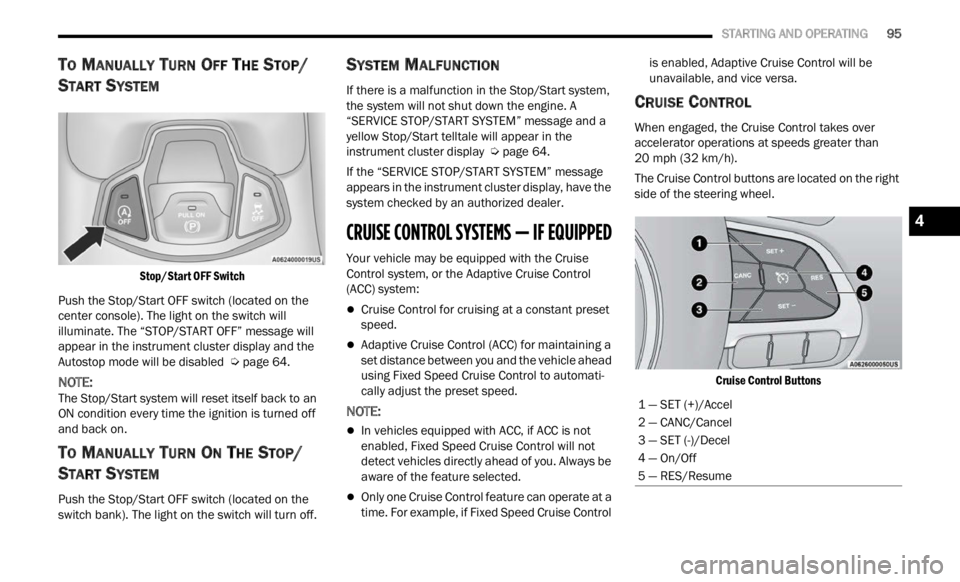
Stop/Start OFF Switch
Push the Stop/Start OFF switch (located on the
center
console). The light on the switch will
illuminate. The “STOP/START OFF” message will
appear in the instrument cluster display and the
Autostop mode will be disabled Ú page 64.
NOTE:
The Stop/Start system will reset itself back to an
ON con d
ition every time the ignition is turned off
and back on.
TO MANUALLY TURN ON THE STOP/
S
TART SYSTEM
Push the Stop/Start OFF switch (located on the
switch bank). The light on the switch will turn off.
SYSTEM MALFUNCTION
If there is a malfunction in the Stop/Start system,
the system will not shut down the engine. A
“SERVICE STOP/START SYSTEM” message and a
yellow Stop/Start telltale will appear in the
instrument cluster display Ú page 64.
If the “SERVICE STOP/START SYSTEM” message
appea r
s in the instrument cluster display, have the
system checked by an authorized dealer.
CRUISE CONTROL SYSTEMS — IF EQUIPPED
Your vehicle may be equipped with the Cruise
Control system, or the Adaptive Cruise Control
(ACC) system:
Cruise Control for cruising at a constant preset
speed.
Adaptive Cruise Control (ACC) for maintaining a
set distance between you and the vehicle ahead
using Fixed Speed Cruise Control to automati -
cally adjust the preset speed.
NOTE:
In vehicles equipped with ACC, if ACC is not
enabled, Fixed Speed Cruise Control will not
detect vehicles directly ahead of you. Always be
aware of the feature selected.
Only one Cruise Control feature can operate at a
time. For example, if Fixed Speed Cruise Control is enabled, Adaptive Cruise Control will be
unavailable, and vice versa.
CRUISE CONTROL
When engaged, the Cruise Control takes over
accelerator operations at speeds greater than
20
mph (32 km/h).
The Cruise Control buttons are located on the right
side of
the steering wheel.
Cruise Control Buttons
1 — SET (+)/Accel
2 — CANC/Cancel
3 — SET (-)/Decel
4 — On/Off
5 — RES/Resume
4
Page 102 of 364

100 STARTING AND OPERATING
To Resume
If there is a set speed in memory, push the RES
(resume) button and remove your foot from the
accelerator pedal. The instrument cluster display
will show the last set speed.
ACC or Fixed Speed Cruise Control can only be
resume
d at speeds above 20 mph (32 km/h).
NOTE:
ACC cannot be resumed if there is a stationary
vehic l
e in front of your vehicle in close proximity.
To Vary The Speed Setting
To Increase Or Decrease The Set Speed
After setting a speed, you can increase the set
sp e
ed
by pushing the SET (+) button, or decrease
speed by pushing the SET (-) button. U.S. Speed (mph)
Pushing the SET (+)
, or SET (-) button once will
result in a 1 mph speed adjustment. Each
subse q
uent tap of the button results in an
adjustment of 1 mph.
If the button is continually pushed, the set
speed will continue to adjust in 5 mph incre-
ments until the button is released. The new set
s peed
is reflected in the instrument cluster
display.
Metric Speed (km/h)
Pushing the SET (+) , or SET (-) button once will
result in a 1 km/h speed adjustment. Each
subse q
uent tap of the button results in an
adjustment of 1 km/h.
If the button is continually pushed, the set
speed will continue to adjust in 10 km/h incre-
ments until the button is released. The new set
s peed
is reflected in the instrument cluster
display.
NOTE:
When you override and push the SET (+) bu t ton or
SET (-) button, the new set speed will be the current
speed of the vehicle. When ACC Is Active:
When you use the SET
(-) button to decelerate, if
the engine’s braking power does not slow the
vehicle sufficiently to reach the set speed, the
brake system will automatically slow the
vehicle.
The ACC system maintains set speed when
driving uphill and downhill. However, a slight
speed change on moderate hills is normal. In
addition, downshifting may occur while climbing
uphill or descending downhill. This is normal
operation and necessary to maintain set speed.
When driving uphill and downhill, the ACC
system will cancel if the braking temperature
exceeds normal range (overheated).
Setting The Following Distance In ACC
The specified following distance for ACC can be set
by varying the distance setting between four bars
(longest), three bars (long), two bars (medium) and
one bar (short). Using this distance setting and the
vehicle speed, ACC calculates and sets the
distance to the vehicle ahead. This distance
setting will show in the instrument cluster display.
WARNING!
The Resume function should only be used if
traffic and road conditions permit. Resuming a
set speed that is too high or too low for
prevailing traffic and road conditions could
cause the vehicle to accelerate or decelerate too
sharply for safe operation. Failure to follow these
warnings can result in a collision and death or
serious personal injury.
Page 104 of 364
102 STARTING AND OPERATING
areas. Under rare conditions, when the radar is not
tracking any vehicles or objects in its path this
warning may temporarily occur.
NOTE:
If the “ACC Front Radar Sensor Temporarily
Blocke d
” warning is active, Fixed Speed Cruise
Control is still available.
If weather conditions are not a factor, the driver
shoul d
examine the sensor. It may require cleaning
or removal of an obstruction. The sensor is located
in the center of the fascia/bumper.
To keep the ACC System operating properly, it is
importa
nt to note the following maintenance
items:
Always keep the sensor clean. Carefully wipe the
sensor lens with a soft cloth. Be cautious not to
damage the sensor lens.
Do not use solvents or abrasive pastes. The
radar is equipped with a defrost system, so in
some climatic conditions it could reach high
temperatures. Wait at least 30 seconds after
the engine has been placed in the OFF mode
before touching the sensor.
Do not remove any screws from the sensor.
Doing so could cause an ACC system malfunc -
tion or failure and require a sensor realignment.
If the sensor or front end of the vehicle is
damaged due to a collision, see your authorized
dealer for service.
Do not attach or install any accessories near the
sensor, including transparent material. Doing so
could cause an ACC system failure or malfunc -
tion.
When the condition that deactivated the system is
n o longe
r present, the system will return to the
“Adaptive Cruise Control Off” state and will resume
function when reactivated.
NOTE:
If the “ACC Front Radar Sensor Temporarily
Blocked” message occurs frequently (e.g. more
than once on every trip) without any snow, rain,
mud, or other obstruction, have the radar
sensor realigned at your authorized dealer.
Installing a snow plow or front-end protector is
not recommended. Doing so may block the
sensor and inhibit ACC/FCW operation.
“CLEAN FRONT WINDSHIELD” WARNING
The “ACC/FCW Limited Functionality Wipe Front
Windshield” warning will display to indicate when
conditions temporarily limit system performance.
This most often occurs at times of poor visibility,
such as in snow or heavy rain and fog. The ACC
system may also become temporarily blinded due
to obstructions, such as mud, dirt, or ice on
windshield and fog on the inside of glass. In these
cases, the instrument cluster display will read “ACC/FCW Limited Functionality Wipe Front
Windshield” and the system will have degraded
performance.
The “ACC/FCW Limited Functionality Wipe Front
Winds
h
ield” message can sometimes be displayed
while driving in adverse weather conditions. The
ACC/FCW system will recover after the vehicle has
left these areas. Under rare conditions, when the
camera is not tracking any vehicles or objects in its
path this warning may temporarily occur.
If weather conditions are not a factor, the driver
should
examine the windshield and the camera
located on the back side of the inside rearview
mirror. They may require cleaning or removal of an
obstruction.
When the condition that created limited
funct i
onality is no longer present, the system will
return to full functionality.
NOTE:
If the “ACC/FCW Limited Functionality Wipe Front
Winds h
ield” message occurs frequently (e.g. more
than once on every trip) without any snow, rain,
mud, or other obstruction, have the windshield and
forward facing camera inspected at an authorized
dealer.
Page 128 of 364
126 STARTING AND OPERATING
(Continued)
TRAILER TOWING WEIGHTS (MAXIMUM TRAILER WEIGHT RATINGS)
The following chart provides the maximum trailer weight ratings towable for your given drivetrain.
TRAILER AND TONGUE WEIGHT
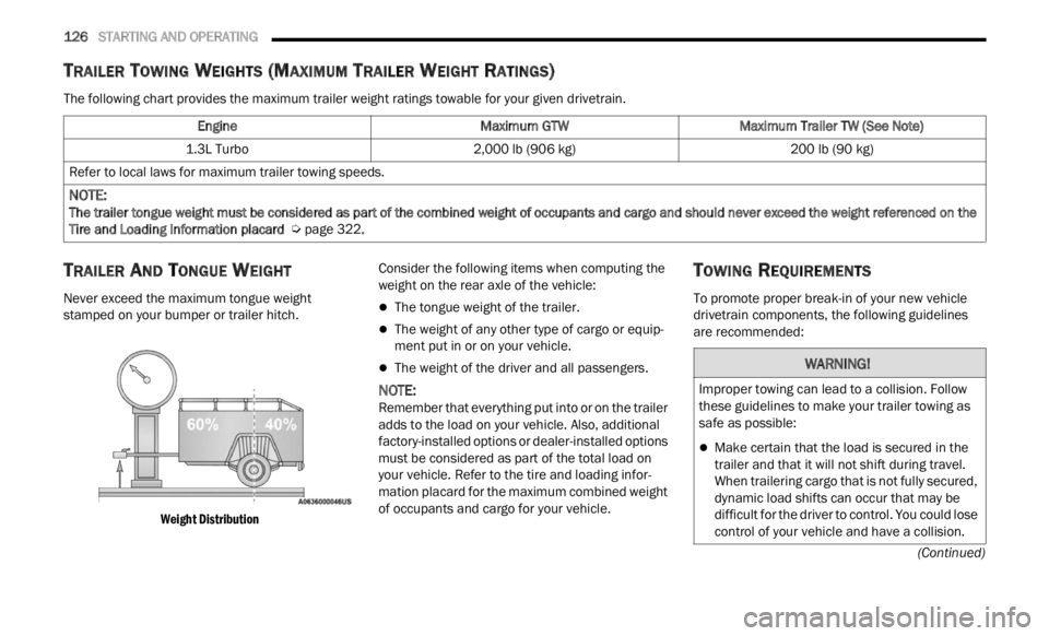
Never exceed the maximum tongue weight
stamped on your bumper or trailer hitch.
Weight Distribution
Consider the following items when computing the
weight
on the rear axle of the vehicle:
The tongue weight of the trailer.
The weight of any other type of cargo or equip -
ment put in or on your vehicle.
The weight of the driver and all passengers.
NOTE:
Remember that everything put into or on the trailer
adds t
o the load on your vehicle. Also, additional
factory-installed options or dealer-installed options
must be considered as part of the total load on
your vehicle. Refer to the tire and loading infor -
mation placard for the maximum combined weight
of occu p
ants and cargo for your vehicle.
TOWING REQUIREMENTS
To promote proper break-in of your new vehicle
drivetrain components, the following guidelines
are recommended:
Engine
Maximum GTWMaximum Trailer TW (See Note)
1.3L Turbo 2,000 lb (906 kg) 200 lb (90 kg)
Refer to local laws for maximum trailer towing speeds.
NOTE:
The trailer tongue weight must be considered as part of the combined weight of occupants and cargo and should never exceed the weight referenced on the
Tire a
nd Loading Information placard Ú page 322.
WARNING!
Improper towing can lead to a collision. Follow
these guidelines to make your trailer towing as
safe as possible:
Make certain that the load is secured in the
trailer and that it will not shift during travel.
When trailering cargo that is not fully secured,
dynamic load shifts can occur that may be
difficult for the driver to control. You could lose
control of your vehicle and have a collision.
Page 129 of 364
STARTING AND OPERATING 127
(Continued)
(Continued)
Towing Requirements — Tires
Do not attempt to tow a trailer while using a
compact spare tire.
Proper tire inflation pressures are essential to
the safe and satisfactory operation of your
vehicle
Ú page 329.
Check the trailer tires for proper tire inflation
pressures before trailer usage.
Check for signs of tire wear or visible tire
damage before towing a trailer Ú page 329.
For the proper tire replacement procedures
Ú page 329. Replacing tires with a higher load
carrying capacity will not increase the vehicle's
G VWR a
nd GAWR limits.
Towing Requirements — Trailer Brakes
Do not interconnect the hydraulic brake system
or vacuum system of your vehicle with that of
the trailer. This could cause inadequate braking
and possible personal injury.
An electronically actuated trailer brake
controller is required when towing a trailer with
electronically actuated brakes. When towing a
trailer equipped with a hydraulic surge actuated
brake system, an electronic brake controller is
not required.
Trailer brakes are recommended for trailers
over 1,000 lb (453 kg) and required for trailers
in excess of 2,000 lb (907 kg).
When hauling cargo, or towing a trailer, do not
overload your vehicle or trailer. Overloading
can cause a loss of control, poor performance,
or damage to brakes, axle, engine, transmis -
sion, steering, suspension, chassis structure,
or tire
s.
Safety chains must always be used between
your vehicle and trailer. Always connect the
chains to the frame or hook retainers of the
vehicle hitch. Cross the chains under the
trailer tongue and allow enough slack for
turning corners.
Vehicles with trailers should not be parked on
a grade. When parking, apply the parking
brake on the tow vehicle. Put the tow vehicle
transmission in PARK. Always block or "chock"
the trailer wheels.
GCWR must not be exceeded.
Total weight must be distributed between the
tow vehicle and the trailer such that the
following four ratings are not exceeded:
GVWR
GTW
WARNING!
GAWR
Tongue weight rating for the trailer hitch
utilized.
CAUTION!
Do not tow a trailer at all during the first
500 miles (805 km) the new vehicle is driven.
The e n
gine, axle or other parts could be
damaged.
Then, during the first 500 miles (805 km) that
a trai
ler is towed, do not drive over 50 mph
( 8
0 k
m /
h) and do not make starts at full
thrott l
e. This helps the engine and other parts
of the vehicle wear in at the heavier loads.
WARNING!
WARNING!
Do not connect trailer brakes to your vehicle's
hydraulic brake lines. It can overload your
brake system and cause it to fail. You might
not have brakes when you need them and
could have a collision.
4
Page 131 of 364

STARTING AND OPERATING 129
Automatic Transmission
Select the DRIVE range when towing. The
transmission controls include a drive strategy to
avoid frequent shifting when towing. However, if
frequent shifting does occur while in DRIVE, you
can use the AutoStick shift control to manually
select a lower gear.
NOTE:
Using a lower gear while operating the vehicle
under
heavy loading conditions will improve perfor -
mance and extend transmission life by reducing
e xcess
ive shifting and heat build up. This action
will also provide better engine braking.
AutoStick
When using the AutoStick shift control, select
the highest gear that allows for adequate perfor -
mance and avoids frequent downshifts. For
exampl
e, choose “5” if the desired speed can be
maintained. Choose “4” or “3” if needed to
maintain the desired speed.
To prevent excess heat generation, avoid
continuous driving at high RPM. Reduce vehicle
speed as necessary to avoid extended driving at
high RPM. Return to a higher gear or vehicle
speed when grade and road conditions allow.
Cruise Control — If Equipped
Do not use in hilly terrain or with heavy loads.
When using the Cruise Control, if you experience
speed drops greater than 10 mph (16 km/h),
d i
s e
n g
age until you can get back to cruising
speed.
Use Cruise Control in flat terrain and with light
loads to maximize fuel efficiency.
RECREATIONAL TOWING
TOWING THIS VEHICLE BEHIND
A
NOTHER VEHICLE
NOTE:
When towing your vehicle, always follow appli -
cable state and provincial laws. Contact state
a nd
p
r
ovincial Highway Safety offices for addi -
tional details.
You must ensure that the Auto Park Brake
feature is disabled before towing this vehicle, to
avoid inadvertent Electric Park Brake engage -
ment. The Auto Park Brake feature is enabled or
disab l
ed via the customer programmable
features in the Uconnect Settings.
RECREATIONAL TOWING
Models With Front-Wheel Drive (FWD)
Recreational towing is allowed ONLY if the front
w he
el
s
are OFF the ground. This may be
accomplished using a tow dolly (front wheels off
the ground) or vehicle trailer (all four wheels off the
ground). If using a tow dolly, follow this procedure:
Properly secure the dolly to the tow vehicle,
following the dolly manufacturer's instructions.
Drive the front wheels onto the tow dolly.
Apply the Electric Park Brake (EPB). Place the
transmission in PARK. Turn the engine off.
Properly secure the front wheels to the dolly,
following the dolly manufacturer's instructions.
Turn the ignition to the RUN position, but do not
start the engine.
Towing
Condit i
on Wheels
Off T h
e
Ground Front-
Wheel
D
rive
(FWD) Four-
Wheel D
rive
(4WD)
Flat Tow NONENOT
ALLOWED N
O
T
ALLOWED
Dol
ly Tow REAR
NOT
ALLOWED N
O
T
ALLOWED
FR
ONT OK NOT
ALLOWED
O n
Trailer ALLBEST
METHOD O
K
4
Page 133 of 364

STARTING AND OPERATING 131
the depth and the bottom condition (and location
of any obstacles) prior to entering. Proceed with
caution and maintain a steady controlled speed
less than 5
mph (8 km/h) in deep water to
minim i
ze wave effects.
Flowing Water
If the water is swift flowing and rising (as in storm
run-of f
) avoid crossing until the water level recedes
and/or the flow rate is reduced. If you must cross
flowing-water, avoid depths in excess of 9 inches
(22 c m
). The flowing water can erode the
streambed causing your vehicle to sink into deeper
water. Determine exit point(s) that are downstream
of your entry point to allow for drifting.
Standing Water — Trailhawk Only
Avoid driving in standing water deeper than
1 9 inch
es (48 cm), and reduce speed
approp r
iately to minimize wave effects. Maximum
speed in 19 inches (48 cm) of water is less than
5 mph (8 km/h).
Maintenance
After driving through deep water, inspect your
v ehic l
e fluids and lubricants (engine, transmission,
Power Transfer Unit and Rear Drive Module) to
ensure they have not been contaminated.
Contaminated fluids and lubricants (milky, foamy
in appearance) should be flushed/changed as
soon as possible to prevent component damage.
Driving In Snow, Mud And Sand
In heavy snow, when pulling a load, or for
additional control at slower speeds, shift the
transmission to a low gear and shift the 4WD
system to the appropriate terrain mode, using
4WD Low if necessary Ú page 91. Do not shift to a
lower gear than necessary to maintain headway.
Over- r
evving the engine can spin the wheels and
traction will be lost.
Avoid abrupt downshifts on icy or slippery roads
becau s
e engine braking may cause skidding and
loss of control.
Hill Climbing
NOTE:
Before attempting to climb a hill, determine the
condit i
ons at the crest and/or on the other side.
Before climbing a steep hill, shift
the transmission
to a lower gear and shift the 4WD System to 4WD
Low. Use first gear and 4WD Low for very steep
hills.
If you stall or begin to lose headway while
climbing
a steep hill, allow your vehicle to come to a stop
and immediately apply the brakes. Restart the
engine and shift to REVERSE. Back slowly down the
hill allowing the compression braking of the engine
to help regulate your speed. If the brakes are
required to control vehicle speed, apply them
lightly and avoid locking or skidding the tires.
NOTE:
Remember, never drive diagonally across a hill -
drive
straight up or down.
If the wheels start to slip as you approach the crest
of a hi
ll, ease off the accelerator and maintain
headway by turning the front wheels slowly left and
right. This may provide a fresh “bite” into the
surface and will usually provide traction to
complete the climb.
Traction Downhill
Shift the transmission into a low gear and the 4WD
System to 4WD Low range or select Hill Descent
Control (if equipped) Ú page 222 . Let the vehicle
go slowly down the hill with all four wheels turning
again s
t engine compression drag. This will permit
you to control the vehicle speed and direction.
When descending mountains or hills, repeated
braki n
g can cause brake fade with loss of braking
control. Avoid repeated heavy braking by
downshifting the transmission whenever possible.
WARNING!
If the engine stalls or you lose headway or
cannot make it to the top of a steep hill or grade,
never attempt to turn around. To do so may
result in tipping and rolling the vehicle. Always
back straight down a hill in REVERSE gear
carefully. Never back down a hill in NEUTRAL
using only the brake.
4
Page 145 of 364

MULTIMEDIA 143
Seats & Comfort
Key Off Options/Engine Off Options
When the Seats & Comfort button is pressed on the touchscreen, the system displays the options related to the vehicle’s comfort systems when remote start
has been activated or the vehicle has been started.
NOTE:
Depending on the vehicle’s options, feature settings may vary.
Setting Name Description
Auto-On Driver Heated/Ventilated Seat & Steering Wheel With Vehicle Start This setting will activate the vehicle’s comfort system and heated seats (if
equip
p
ed) or heated steering wheel (if equipped) when the vehicle is remote
started or ignition is started. The “Off” setting will not activate the comfort
systems. The “Remote Start” setting will only activate the comfort systems
when using Remote Start. The “All Start” setting will activate the comfort
systems whenever the vehicle is started.
When the Key Off Options/Engine Off Options button is pressed on the touchscreen, the system displays the options related to vehicle shutoff. These settings
will only activate when the ignition is set to OFF.
NOTE:
Depending on the vehicle’s options, feature settings may vary.
Setting Name Description
Radio Off Delay This setting will keep the radio on for the selected amount of time after
vehic
l
e shut off. The available options are “0 sec” or “20 min”.
Radio Off With Door This setting will shut the radio off when the door is opened. The available
s
etti
n
gs are “On” and “Off”.
5