ESP JEEP RENEGADE 2023 Owners Manual
[x] Cancel search | Manufacturer: JEEP, Model Year: 2023, Model line: RENEGADE, Model: JEEP RENEGADE 2023Pages: 364, PDF Size: 18.65 MB
Page 2 of 364

The driver’s primary responsibility is the safe operation of the vehicle. Driving while distracted can result in loss of vehicle control,
resulting in an accident and personal injury. FCA US LLC strongly recommends that the driver use extreme caution when using any device
or feature that may take their attention off the road. Use of any electrical devices, such as cellular telephones, computers, portable radios,
vehicle navigation or other devices, by the driver while the vehicle is moving is dangerous and could lead to a serious accident. Texting
while driving is also dangerous and should never be done while the vehicle is moving. If you find yourself unable to devote your full
attention to vehicle operation, pull off the road to a safe location and stop your vehicle. Some states or provinces prohibit the use of
cellular telephones or texting while driving. It is always the driver’s responsibility to comply with all local laws.
This Owner’s Manual has been prepared to help you get acquainted with your new Jeep
® brand vehicle and to provide a convenient
reference source for common questions.
Not all features shown in this manual may apply to your vehicle. For additional information, visit mopar.com/om (U.S.), owners.mopar.ca
(Canada) or your local Jeep
® brand dealer.
DRIVING AND ALCOHOL
Drunk driving is one of the most frequent causes of accidents. Your driving ability can be seriously impaired with blood alcohol levels
far below the legal minimum. If you are drinking, don’t drive. Ride with a designated non-drinking driver, call a cab, a rideshare, a friend
or use public transportation.
WARNING
Driving after drinking can lead to an accident. Your perceptions are less sharp, your reflexes are slower and your judgment is impaired
when you have been drinking. Never drink and then drive.
WARNING: Operating, servicing and maintaining a passenger vehicle or off-highway
motor vehicle can expose you to chemicals including engine exhaust, carbon monoxide,
phthalates, and lead, which are known to the State of California to cause cancer and birth
defects or other reproductive harm. To minimize exposure, avoid breathing exhaust,
do not idle the engine except as necessary, service your vehicle in a well-ventilated area
and wear gloves or wash your hands frequently when servicing your vehicle. For more
information go to
www.P65Warnings.ca.gov/passenger-vehicle.
This Owner’s Manual illustrates and describes the operation of features and equipment that are either standard or optional on this
vehicle. This manual may also include a description of features and equipment that are no longer available or were not ordered on
this vehicle. Please disregard any features and equipment described in this manual that are not on this vehicle. FCA US LLC reserves the
right to make changes in design and specifications, and/or make additions to or improvements to its products without imposing any
obligation upon itself to install them on products previously manufactured.
With respect to any vehicles sold in Canada, the name FCA US LLC shall be deemed to be deleted and the name FCA Canada Inc.
used in substitution therefore.
This Owner’s Manual is intended to familiarize you with the important features of your vehicle. Your most up-to-date Owner’s Manual,
Navigation/Uconnect manuals and Warranty Booklet can be found by visiting the website on the back cover.
U.S. Residents: If you are the first registered retail owner of your vehicle, you may obtain a complimentary printed copy of the Warranty
Booklet by calling 1-877-426-5337 or by contacting your dealer. Replacement kits can be purchased by visiting www.techauthority.com.
Canadian Residents: If you are the first registered retail owner of your vehicle, you may obtain a complimentary printed copy of the
Warranty Booklet or purchase a replacement kit by calling 1-800-387-1143 or by contacting your dealer.
Page 8 of 364
6
REFUELING IN EMERGENCY – IF EQUIPPED .. 280
IF YOUR ENGINE OVERHEATS ...... ...................... 281
GEAR SELECTOR OVERRIDE ...... ....................... 281
FREEING A STUCK VEHICLE ...... ........................ 282
TOWING A DISABLED VEHICLE ...... ...................283
Front–Wheel Drive (FWD) ...... ....................... 284
Four–Wheel Drive (4WD) ..... . ........................ 284
Emergency Tow Hooks — If Equipped . ..
..
. .... 284
ENHANCED ACCIDENT RESPONSE SYSTEM
(EARS) .................................................................. 285
EVEN T
DATA RECORDER (EDR) ...... ...................285
SERVICING AND MAINTENANCE
SCHEDULED SERVICING .................................... 286
Maintenance Plan ...... ................................... 287
ENGINE COMPARTMENT ..... . .............................. 293
1.3L Turbo Engine ...... ................................... 293
Checking Oil Level ..... . ................................... 294
Adding Washer Fluid . ..
..
. ............................... 294
Maintenance-Free Battery ..... . ..................... 294
Pressure Washing . ..
..
. ................................... 295
VEHICLE MAINTENANCE ..... . .............................. 295
Engine Oil ...................................................... 295
Engin e Oil Filter . ..
..
. ....................................... 296
Engine Air Cleaner Filter ..... . ........................ 296
Air Conditioner Maintenance . ..
..
. .................. 296Body Lubrication .....
.
..................................... 297
Windshield Wiper Blades ..... . ....................... 297
Exhaust System ..... . ...................................... 298
Cooling System . ..
..
. ........................................ 299
Brake System ..... . .......................................... 302
Automatic Transmission . ..
..
. ........................ 303
Fuses.............................................................. 303
Bulb
Replacement. ..
..
. ................................... 311
TIRES..................................................................... 322
Tire
Safety Information ...... ........................... 322
Tires — General Information . ..
..
. .................. 329
Tire Types....................................................... 332
Spar e
Tires — If Equipped . ..
. .
. ....................... 333
Wheel And Wheel Trim Care ..... . ................... 334
Snow Traction Devices . ..
..
. ........................... 335
Tire Rotation Recommendations ..... . .......... 336
DEPARTMENT OF TRANSPORTATION
UNIFORM TIRE QUALITY GRADES ..... .
............. 337
Treadwear ...................................................... 337
Tract ion Grades . ..
..
. ....................................... 337
Temperature Grades ..... . ............................... 337
STORING THE VEHICLE . ..
..
. ................................. 338
BODYWORK ...... ................................................... 338
Protection From Atmospheric Agents ...... .... 338
Body And Underbody Maintenance. ..
..
. ........ 338
Preserving The Bodywork ..... . ....................... 338INTERIORS .....
.
..................................................... 339
Seats And Fabric Parts ...... ........................... 339
Plastic And Coated Parts ..... . ........................ 339
Leather Surfaces. ..
..
. ..................................... 340
Glass Surfaces ..... . ....................................... 340
TECHNICAL SPECIFICATIONS
VEHICLE IDENTIFICATION NUMBER (VIN) ........ 341
BRAKE SYSTEM ...... ............................................. 341
WHEEL AND TIRE TORQUE SPECIFICATIONS .. 341 Tor que Specifications ...... ............................. 341
FUEL REQUIREMENTS . ..
..
. ................................... 342
1.3L Turbo Engine ...... ................................... 342
Reformulated Gasoline..... . ........................... 342
Gasoline/Oxygenate Blends . ..
..
. .................. 342
E-85 Usage In Non-Flex Fuel Vehicles ..... . ... 343
CNG And LP Fuel System Modifications . ..
..
. 343
Methylcyclopentadienyl Manganese
Tricarbonyl (MMT) In Gasoline . .....
............... 343
Materials Added To Fuel ..... . ......................... 343
Fuel System Cautions ..... . ............................. 344
FLUID CAPACITIES . ..
..
. ......................................... 344
ENGINE FLUIDS AND LUBRICANTS ...... ............ 345
CHASSIS FLUIDS AND LUBRICANTS ...... .......... 345
Page 24 of 364
22 GETTING TO KNOW YOUR VEHICLE
POWER DOOR LOCKS
The power door lock switches are located on each
front door panel. Push the switch to lock or unlock
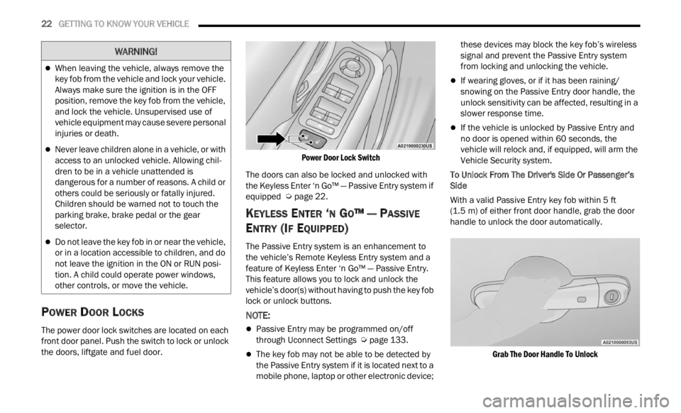
the doors, liftgate and fuel door.
Power Door Lock Switch
The doors can also be locked and unlocked with
the K e
yless Enter ‘n Go™ — Passive Entry system if
equipped Ú page 22.
KEYLESS ENTER ‘N GO™ — PASSIVE
E
NTRY (IF EQUIPPED)
The Passive Entry system is an enhancement to
the vehicle’s Remote Keyless Entry system and a
feature of Keyless Enter ‘n Go™ — Passive Entry.
This feature allows you to lock and unlock the
vehicle’s door(s) without having to push the key fob
lock or unlock buttons.
NOTE:
Passive Entry may be programmed on/off
through Uconnect Settings Ú page 133.
The key fob may not be able to be detected by
the Passive Entry system if it is located next to a
mobile phone, laptop or other electronic device; these devices may block the key fob’s wireless
signal and prevent the Passive Entry system
from locking and unlocking the vehicle.
If wearing gloves, or if it has been raining/
snowing on the Passive Entry door handle, the
unlock sensitivity can be affected, resulting in a
slower response time.
If the vehicle is unlocked by Passive Entry and
no door is opened within 60 seconds, the
vehicle will relock and, if equipped, will arm the
Vehicle Security system.
To Unlock From The Driver's Side Or Passenger’s
Side
Wit
h a valid Passive Entry key fob within 5 ft
(1.5 m)
of either front door handle, grab the door
handl e
to unlock the door automatically.
Grab The Door Handle To Unlock
When leaving the vehicle, always remove the
key fob from the vehicle and lock your vehicle.
Always make sure the ignition is in the OFF
position, remove the key fob from the vehicle,
and lock the vehicle. Unsupervised use of
vehicle equipment may cause severe personal
injuries or death.
Never leave children alone in a vehicle, or with
access to an unlocked vehicle. Allowing chil -
dren to be in a vehicle unattended is
d anger
ous for a number of reasons. A child or
others could be seriously or fatally injured.
Children should be warned not to touch the
parking brake, brake pedal or the gear
selector.
Do not leave the key fob in or near the vehicle,
or in a location accessible to children, and do
not leave the ignition in the ON or RUN posi -
tion. A child could operate power windows,
other c
ontrols, or move the vehicle.
WARNING!
Page 28 of 364
26 GETTING TO KNOW YOUR VEHICLE
(Continued)
STEERING WHEEL
TILT/TELESCOPING STEERING COLUMN
This feature allows you to tilt the steering column
upward or downward. It also allows you to lengthen
or shorten the steering column. The tilt/
telescoping lever is located below the steering
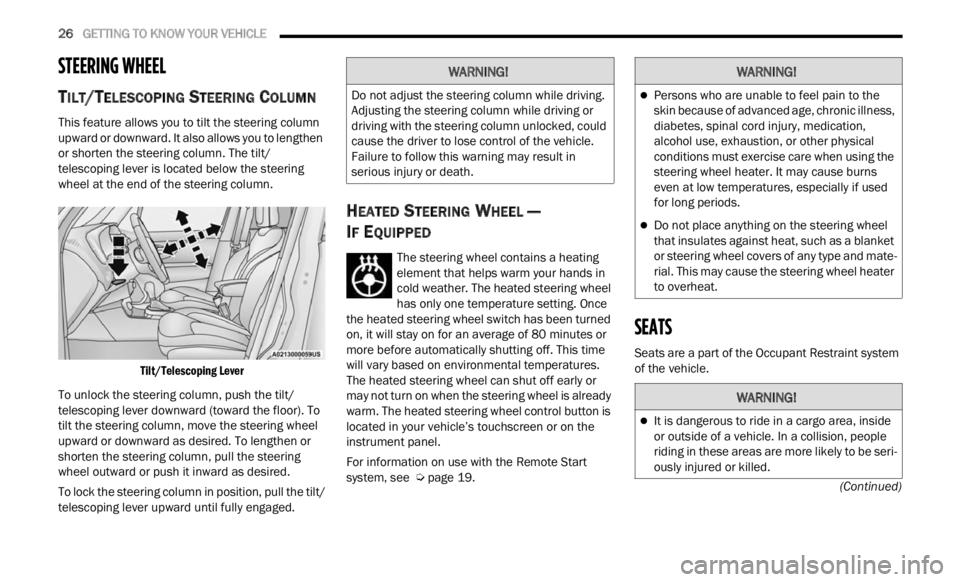
wheel at the end of the steering column.
Tilt/Telescoping Lever
To unlock the steering column, push the tilt/
telesc
oping lever downward (toward the floor). To
tilt the steering column, move the steering wheel
upward or downward as desired. To lengthen or
shorten the steering column, pull the steering
wheel outward or push it inward as desired.
To lock the steering column in position, pull the tilt/
teles c
oping lever upward until fully engaged.
HEATED STEERING WHEEL —
I
F EQUIPPED
The steering wheel contains a heating
element that helps warm your hands in
cold w e
ather. The heated steering wheel
has only one temperature setting. Once
the heated steering wheel switch has been turned
on, it will stay on for an average of 80 minutes or
more be
fore automatically shutting off. This time
will vary based on environmental temperatures.
The heated steering wheel can shut off early or
may not turn on when the steering wheel is already
warm. The heated steering wheel control button is
located in your vehicle’s touchscreen or on the
instrument panel.
For information on use with the Remote Start
syste m
, see Ú page 19.
SEATS
Seats are a part of the Occupant Restraint system
of the vehicle.
WARNING!
Do not adjust the steering column while driving.
Adjusting the steering column while driving or
driving with the steering column unlocked, could
cause the driver to lose control of the vehicle.
Failure to follow this warning may result in
serious injury or death.
WARNING!
Persons who are unable to feel pain to the
skin because of advanced age, chronic illness,
diabetes, spinal cord injury, medication,
alcohol use, exhaustion, or other physical
conditions must exercise care when using the
steering wheel heater. It may cause burns
even at low temperatures, especially if used
for long periods.
Do not place anything on the steering wheel
that insulates against heat, such as a blanket
or steering wheel covers of any type and mate
-
rial. This may cause the steering wheel heater
to over h
eat.
WARNING!
It is dangerous to ride in a cargo area, inside
or outside of a vehicle. In a collision, people
riding in these areas are more likely to be seri -
ously injured or killed.
Page 32 of 364
30 GETTING TO KNOW YOUR VEHICLE
Power Lumbar Adjustment— If Equipped
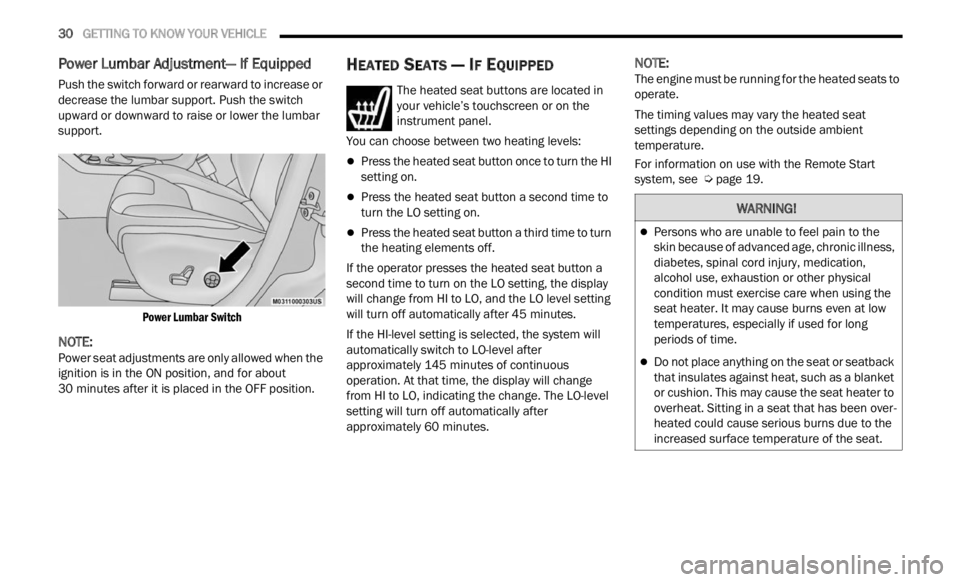
Push the switch forward or rearward to increase or
decrease the lumbar support. Push the switch
upward or downward to raise or lower the lumbar
support.
Power Lumbar Switch
NOTE:
Power seat adjustments are only allowed when the
ignit i
on is in the ON position, and for about
30 minutes after it is placed in the OFF position.
HEATED SEATS — IF EQUIPPED
The heated seat buttons are located in
your vehicle’s touchscreen or on the
instr u
ment panel.
You can choose between two heating levels:
Press the heated seat button once to turn the HI
setting on.
Press the heated seat button a second time to
turn the LO setting on.
Press the heated seat button a third time to turn
the heating elements off.
If the operator presses the heated seat button a
second
time to turn on the LO setting, the display
will change from HI to LO, and the LO level setting
will turn off automatically after 45 minutes.
If the HI-level setting is selected, the system will
a utomat
ically switch to LO-level after
approximately 145 minutes of continuous
operati
on. At that time, the display will change
from HI to LO, indicating the change. The LO-level
setting will turn off automatically after
approximately 60 minutes.
NOTE:
The engine must be running for the heated seats to
operat e
.
The timing values may vary the heated seat
settin
gs depending on the outside ambient
temperature.
For information on use with the Remote Start
syste m
, see Ú page 19.
WARNING!
Persons who are unable to feel pain to the
skin because of advanced age, chronic illness,
diabetes, spinal cord injury, medication,
alcohol use, exhaustion or other physical
condition must exercise care when using the
seat heater. It may cause burns even at low
temperatures, especially if used for long
periods of time.
Do not place anything on the seat or seatback
that insulates against heat, such as a blanket
or cushion. This may cause the seat heater to
overheat. Sitting in a seat that has been over
-
heated could cause serious burns due to the
i ncrea
sed surface temperature of the seat.
Page 62 of 364
60 GETTING TO KNOW YOUR VEHICLE
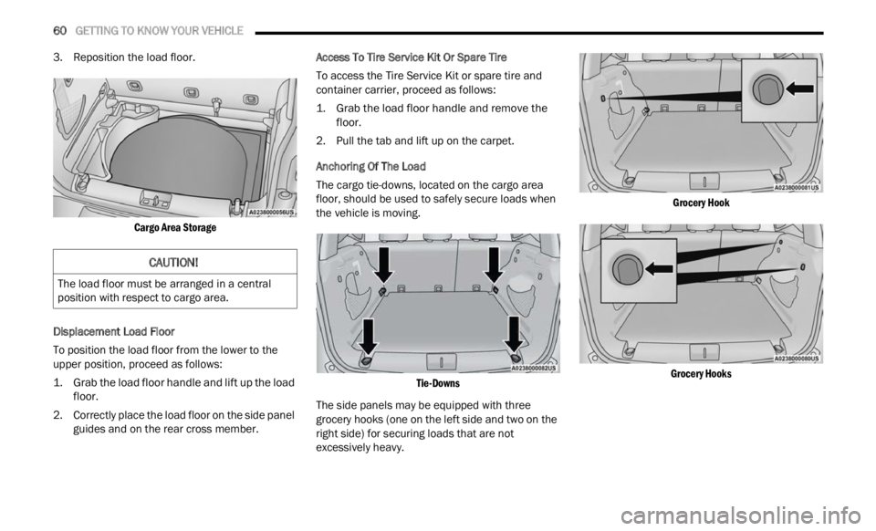
3. Reposition the load floor.
Cargo Area Storage
Displacement Load Floor
To position the load floor from the lower to the
u pper
position, proceed as follows:
1. Grab the load floor handle and lift up the load floor.
2.
Correctly place the load floor on the side panel
guide
s and on the rear cross member. Access To Tire Service Kit Or Spare Tire
To access the Tire Service Kit or spare tire and
c
ontai n
er carrier, proceed as follows:
1. Grab the load floor handle and remove the floor.
2.
Pull the tab and lift up on the carpet.
Anchor
ing Of The Load
The cargo tie-downs, located on the cargo area
f loor, s
hould be used to safely secure loads when
the vehicle is moving.
Tie-Downs
The side panels may be equipped with three
grocery
hooks (one on the left side and two on the
right side) for securing loads that are not
excessively heavy.
Grocery Hook
Grocery Hooks
CAUTION!
The load floor must be arranged in a central
position with respect to cargo area.
Page 71 of 364

GETTING TO KNOW YOUR INSTRUMENT PANEL 69
Sound Horn With Lock: activate/deactivate the
horn when pushing the LOCK button on the key
fob. The options are “Off,” “First Press,” and
“Second Press”
Horn With Remote Start: activate/deactivate
the horn at the Remote Starting of the engine
with the key fob
Remote Door Unlock: allows you to open the
driver door only on the first push of the UNLOCK
button on the key fob
“Compass”
By selecting the item “Compass” you can make the
f ollowi
ng adjustments:
Compass Calibration
Compass Variance
TRIP COMPUTER
The Trip computer is used to display information on
car operation when the key is turned to the RUN
position.
This function allows you to define two separate
trips
called “Trip A” and “Trip B” where the car's
“complete trips” are monitored in an independent
manner.
Both trips can be reset (reset - start of a new trip).
To perf
orm a reset, push and hold the OK button on
the steering wheel controls. “Trip A” and “Trip B” are used to display the figures
relat
i
ng to:
Distance Traveled
Average Consumption
Travel Time (driving time)
Quantities Displayed
Distance Traveled
Indicates the distance traveled by the start of
the new trip.
Average Consumption
Represents the average fuel consumption since
the start of the new trip.
Travel Time
Elapsed time since the start of the new trip.
OK Button
Short Push Of The Button: display of various
p arame
ters.
Long Push Of The Button: reset quantities and
begin
a new trip.
New trip
Starts after reset:
“Manual” by pushing the OK button.
“Automatic” when the “distance” reaches the
value of 62140 (99999.9 km) or when the “time
travel” reaches the value of 999.59
(999 hours and 59 minutes).
After each disconnection and reconnection of
the battery.
WARNING/INDICATOR LIGHTS AND
MESSAGES
The warning/indicator light switches on in the
instrument panel together with a dedicated
message and/or acoustic signal when applicable.
These indications are indicative and precautionary
and as such must not be considered as exhaustive
and/or alternative to the information contained in
the Owner Manual, which you are advised to read
carefully in all cases. Always refer to the
information in this chapter in the event of a failure
indication.
All active telltales will display first, if applicable.
The sy
stem check menu may appear different
based upon equipment options and current vehicle
status. Some telltales are optional and may not
appear.
The following warning lamps and indicators will
alert
you to a vehicle condition that may become
serious. Some lamps will illuminate when you start
your vehicle to make sure they work. If any lamps
remain on after starting your vehicle, refer to the
respective system warning lamp for further
information.
3
Page 76 of 364
74 GETTING TO KNOW YOUR INSTRUMENT PANEL
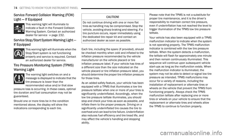
Service Forward Collision Warning (FCW)
Light — If Equipped
This warning light will illuminate to
indicate a fault in the Forward Collision
W
ar
n i
n
g System. Contact an authorized
dealer for service Ú page 232.
Service Stop/Start System Warning Light —
If Equipped
This warning light will illuminate when the
Stop/Start system is not functioning
p
rop
er
l
y and service is required. Contact
an authorized dealer for service.
Tire Pressure Monitoring System (TPMS)
Warning Light
The warning light switches on and a
message is displayed to indicate that the
tire p
ressure is lower than the
recommended value and/or that slow
pressure loss is occurring. In these cases, optimal
tire duration and fuel consumption may not be
guaranteed.
Should one or more tires be in the condition
mention
ed above, the display will show the
indications corresponding to each tire. Each tire, including the spare (if provided), should
be ch
e
cked monthly when cold and inflated to the
inflation pressure recommended by the vehicle
manufacturer on the vehicle placard or tire
inflation pressure label. If your vehicle has tires of
a different size than the size indicated on the
vehicle placard or tire inflation pressure label, you
should determine the proper tire inflation pressure
for those tires.
As an added safety feature, your vehicle has been
equip p
ed with a TPMS that illuminates a low tire
pressure telltale when one or more of your tires is
significantly underinflated. Accordingly, when the
low tire pressure telltale illuminates, you should
stop and check your tires as soon as possible, and
inflate them to the proper pressure. Driving on a
significantly underinflated tire causes the tire to
overheat and can lead to tire failure. Underinflation
also reduces fuel efficiency and tire tread life, and
may affect the vehicle’s handling and stopping
ability. Please note that the TPMS is not a substitute for
proper
tire maintenance, and it is the driver’s
responsibility to maintain correct tire pressure,
even if underinflation has not reached the level to
trigger illumination of the TPMS low tire pressure
telltale.
Your vehicle has also been equipped with a TPMS
malfu n
ction indicator to indicate when the system
is not operating properly. The TPMS malfunction
indicator is combined with the low tire pressure
telltale. When the system detects a malfunction,
the telltale will flash for approximately one minute
and then remain continuously illuminated. This
sequence will continue upon subsequent vehicle
start-ups as long as the malfunction exists. When
the malfunction indicator is illuminated, the
system may not be able to detect or signal low tire
pressure as intended. TPMS malfunctions may
occur for a variety of reasons, including the
installation of replacement or alternate tires or
wheels on the vehicle that prevent the TPMS from
functioning properly. Always check the TPMS
malfunction telltale after replacing one or more
tires or wheels on your vehicle to ensure that the
replacement or alternate tires and wheels allow
the TPMS to continue to function properly.
CAUTION!
Do not continue driving with one or more flat
tires as handling may be compromised. Stop the
vehicle, avoiding sharp braking and steering. If a
tire puncture occurs, repair immediately using
the dedicated tire repair kit and contact an
authorized dealer as soon as possible.
Page 78 of 364
76 GETTING TO KNOW YOUR INSTRUMENT PANEL
at speeds greater than 30 mph (48 km/h), see an
authori
zed dealer as soon as possible to have the
problem diagnosed and corrected.
The ESC OFF Indicator Light and the ESC Indi -
cator Light come on momentarily each time the
ignit i
on is placed in the ON/RUN or ACC/ON/
RUN position.
The ESC system will make buzzing or clicking
sounds when it is active. This is normal; the
sounds will stop when ESC becomes inactive.
This light will come on when the vehicle is in an
ESC event.
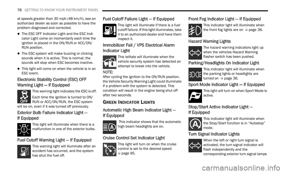
Electronic Stability Control (ESC) OFF
Warning Light — If Equipped
This warning light indicates the ESC is off.
Each time the ignition is turned to ON/
RUN or
ACC/ON/RUN, the ESC system
will be on, even if it was turned off previously.
Exterior Bulb Failure Indicator Light —
If Equipped
This light will illuminate when there is a
malfunction in one of the exterior bulbs.
Fuel Cutoff Warning Light — If Equipped
This warning light will illuminate after an
accident has occurred, and the system
has s h
ut the fuel off.
Fuel Cutoff Failure Light — If Equipped
This light will illuminate if there is a fuel
cutoff failure. If this light illuminates, take
it to a
n authorized dealer and have them
inspect it.
Immobilizer Fail / VPS Electrical Alarm
Indicator Light
This telltale will illuminate when the
vehicle security system has detected an
a tt
e m
p
t to break into the vehicle.
NOTE:
After cycling the ignition to the ON/RUN position,
the V e
hicle Security Warning Light could illuminate
if a problem with the system is detected. This
condition will result in the engine being shut off
after two seconds.
GREEN INDICATOR LIGHTS
Automatic High Beam Indicator Light —
If Equipped
This indicator shows that the automatic
high beam headlights are on.
Cruise Control Set Indicator Light
This light will turn on when the cruise
control is set to the desired speed
Ú page 95.
Front Fog Indicator Light — If Equipped
This indicator light will illuminate when
the front fog lights are on Ú page 36.
Hazard Warning Lights
The hazard warning indicators light up
when the vehicles Hazard Warning
flash e
r switch has been pushed.
Parking/Headlights On Indicator Light
This indicator light will illuminate when
the parking lights or headlights are
tu r
n e
d
on Ú page 36.
Sport Mode Indicator Light — If Equipped
This light will turn on when Sport Mode is
active.
Stop/Start Active Indicator Light —
If Equipped
This indicator light will illuminate when
the Stop/Start function is in “Autostop”
mode.
Turn Signal Indicator Lights
When the left or right turn signal is
activated, the turn signal indicator will
f la
sh
independently and the
corresponding exterior turn signal lamps
Page 89 of 364
STARTING AND OPERATING 87
(Continued)
(Continued)
GEAR RANGES
PARK (P)
This range supplements the Electric Park Brake
(
E P
B )
by locking the transmission. The engine can
be started in this range. Never attempt to use
PARK while the vehicle is in motion.
When parking on a hill, apply the EPB before
shifti
ng the transmission to PARK, otherwise the
load on the transmission locking mechanism may
make it difficult to move the gear selector out of
PARK. As an added precaution, turn the front
wheels toward the curb on a downhill grade and
away from the curb on an uphill grade.
When exiting the vehicle, always:
Apply the parking brake.
Shift the transmission into PARK.
Turn the ignition OFF.
Remove the key fob from the vehicle.
CAUTION!
After selecting any gear range, wait a moment to
allow the selected gear to engage before
accelerating. This is especially important when
the engine is cold.
WARNING!
Never use the PARK position as a substitute
for the parking brake. Always apply the
parking brake fully when exiting the vehicle to
guard against vehicle movement and possible
injury or damage.
Your vehicle could move and injure you and
others if it is not in PARK. Check by trying to
move the transmission gear selector out of
PARK with the brake pedal released. Make
sure the transmission is in PARK before
exiting the vehicle.
The transmission may not engage PARK if the
vehicle is moving. Always bring the vehicle to a
complete stop before shifting to PARK, and
verify that the transmission gear position indi -
cator solidly indicates PARK (P) without
b linki
ng. Ensure that the vehicle is completely
stopped, and the PARK position is properly
indicated, before exiting the vehicle.
It is dangerous to shift out of PARK or
NEUTRAL if the engine speed is higher than
idle speed. If your foot is not firmly pressing
the brake pedal, the vehicle could accelerate
quickly forward or in reverse. You could lose
control of the vehicle and hit someone or
something. Only shift into gear when the
engine is idling normally (or stopped) and your
foot is firmly pressing the brake pedal.
Unintended movement of a vehicle could
injure those in or near the vehicle. As with all
vehicles, you should never exit a vehicle while
the engine is running or the propulsion system
is active. Before exiting a vehicle, always come
to a complete stop, then apply the parking
brake, shift the transmission into PARK, and
turn the ignition OFF. When the ignition is in
the OFF position, the transmission is locked in
PARK, securing the vehicle against unwanted
movement.
When leaving the vehicle, always make sure
the ignition is in the OFF position, remove the
key fob from the vehicle, and lock the vehicle.
WARNING!
4