ESP JEEP WAGONEER 2023 User Guide
[x] Cancel search | Manufacturer: JEEP, Model Year: 2023, Model line: WAGONEER, Model: JEEP WAGONEER 2023Pages: 396, PDF Size: 15.17 MB
Page 90 of 396
88GETTING TO KNOW YOUR VEHICLE
NOTE:The activation zone is the same for vehicles equipped with
or without a trailer tow package.
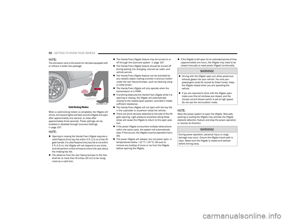
Valid Kicking Motion
When a valid kicking motion is completed, the liftgate will
chime, the hazard lights will flash and the liftgate will open
after approximately one second, or close after
approximately three seconds. These settings can be
enabled or disabled through Uconnect Settings
Úpage 197.
NOTE:
Opening or closing the Hands-Free Liftgate requires a
valid Passive Entry key fob within 5 ft (1.5 m) of the lift -
gate handle. If a valid Passive Entry key fob is not within
5 ft (1.5 m), the liftgate will not respond to any kicks,
and will perform inhibit chimes to inform the user about
the missing key fob.
The distance from the rear fascia/bumper to the foot
shall be no more than 8 inches (20 cm) to be recog -
nized as a valid kick.
The Hands-Free Liftgate feature may be turned on or
off through the Uconnect system
Úpage 197.
The Hands-Free Liftgate feature should be turned off
during jacking, tire changing, manual car wash, and
vehicle service.
The Hands-Free Liftgate feature can be activated by
any metallic object making a similar in-and-out motion
under the rear fascia/bumper, such as cleaning using
a metal broom.
The Hands-Free Liftgate will only operate when the
transmission is in PARK.
If anything obstructs the Hands-Free Liftgate while it is
opening or closing, the liftgate will automatically
reverse to the closed/open position, provided it meets
sufficient resistance.
The Hands-Free Liftgate will not open with the key fob
in the cupholder or anywhere inside the vehicle.
There are pinch sensors attached to the side of the lift -
gate opening. Light pressure anywhere along these
strips will cause the liftgate to return to the open posi -
tion.
If the power liftgate encounters multiple obstructions
within the same cycle, the system will automatically
stop. If this occurs, the liftgate must be operated manu -
ally.
The power liftgate will release, but not power open, in
temperatures below −12°F (−24°C). Be sure to
remove any buildup of snow or ice from the liftgate
before opening the liftgate.
If the liftgate is left open for an extended period of time
(approximately one hour), the liftgate may need to be
closed manually to reset power liftgate functionality.
NOTE:Allow the power system to open the liftgate. Manually
pushing or pulling the liftgate may activate the liftgate
obstacle detection feature and stop the power operation
or reverse its direction.
WARNING!
Driving with the liftgate open can allow poisonous
exhaust gases into your vehicle. You and your
passengers could be injured by these fumes. Keep
the liftgate closed when you are operating the
vehicle.
If you are required to drive with the liftgate open,
make sure that all windows are closed, and the
climate control blower switch is set at high speed.
Do not use the recirculation mode.
WARNING!
During power operation, personal injury or cargo
damage may occur. Ensure the liftgate travel path is
clear. Make sure the liftgate is closed and latched
before driving away.
23_WS_OM_EN_USC_t.book Page 88
Page 96 of 396

94GETTING TO KNOW YOUR VEHICLE
(Continued)
6. Repeat steps 2-5 for the second crossbar in the
desired position.
Installed Crossbars
WARNING!
Cargo must be securely tied down before driving your
vehicle. Anything improperly secured to the roof rack,
crossbars, or the roof itself can fly off the vehicle,
particularly at high speeds, resulting in collisions,
personal injury or property damage. Follow the roof rack
cautions when carrying anything on your roof or
roof rack.
CAUTION!
To prevent damage to the roof of your vehicle, DO
NOT carry any loads on the roof rack without the
crossbars installed. The load should be secured and
placed on top of the crossbars, not directly on the
roof. If it is necessary to place the load on the roof,
place a blanket or other protective layer between the
load and the roof surface.
To avoid damage to the roof rack and vehicle, do not
exceed the maximum roof rack load capacity of 150
lb (68 kg). Always distribute heavy loads as evenly as
possible and appropriately secure the load and any
protective layer placed between the load and the roof
surface.
Load should always be secured to crossbars first,
with tie down loops used as additional securing
points if needed. Tie loops are intended as supple -
mentary tie down points only. Do not use ratcheting
mechanisms with the tie loops. Check the straps and
thumb wheels frequently to be sure that the load
remains securely attached. Long loads that extend over the windshield, such as
wood panels or surfboards, or loads with large frontal
area should be secured to both the front and rear of
the vehicle.
Travel at reduced speeds and turn corners carefully
when carrying large or heavy loads on the roof rack.
Wind forces, due to natural causes or nearby truck
traffic, can add sudden upward lift to a load. This is
especially true on large flat loads and may result in
damage to the cargo or your vehicle.
CAUTION!
23_WS_OM_EN_USC_t.book Page 94
Page 116 of 396
114GETTING TO KNOW YOUR INSTRUMENT PANEL
Tire Pressure Monitoring System (TPMS)
Warning Light
The warning light switches on and a message is
displayed to indicate that the tire pressure is
lower than the recommended value and/or
that slow pressure loss is occurring. In these
cases, optimal tire duration and fuel consumption may not
be guaranteed.
Should one or more tires be in the condition mentioned
previously, the display will show the indications
corresponding to each tire.
Each tire, including the spare (if provided), should be
checked monthly when cold and inflated to the inflation
pressure recommended by the vehicle manufacturer on
the vehicle placard or tire inflation pressure label. If your
vehicle has tires of a different size than the size indicated
on the vehicle placard or tire inflation pressure label, you
should determine the proper tire inflation pressure for
those tires. As an added safety feature, your vehicle has been
equipped with a TPMS that illuminates a low tire pressure
telltale when one or more of your tires is significantly
underinflated. Accordingly, when the low tire pressure
telltale illuminates, you should stop and check your tires
as soon as possible, and inflate them to the proper
pressure. Driving on a significantly underinflated tire
causes the tire to overheat and can lead to tire failure.
Underinflation also reduces fuel efficiency and tire tread
life, and may affect the vehicle’s handling and stopping
ability.
Please note that the TPMS is not a substitute for proper
tire maintenance, and it is the driver’s responsibility to
maintain correct tire pressure, even if underinflation has
not reached the level to trigger illumination of the TPMS
low tire pressure telltale.
Your vehicle has also been equipped with a TPMS
malfunction indicator to indicate when the system is not
operating properly. The TPMS malfunction indicator is
combined with the low tire pressure telltale. When the
system detects a malfunction, the telltale will flash for
approximately one minute and then remain continuously
illuminated. This sequence will continue upon subsequent
vehicle start-ups as long as the malfunction exists. When
the malfunction indicator is illuminated, the system may
not be able to detect or signal low tire pressure as
intended. TPMS malfunctions may occur for a variety of
reasons, including the installation of replacement or
alternate tires or wheels on the vehicle that prevent the
TPMS from functioning properly. Always check the TPMS
malfunction telltale after replacing one or more tires or
wheels on your vehicle to ensure that the replacement or
alternate tires and wheels allow the TPMS to continue to
function properly
Úpage 252.
Towing Hook Breakdown Warning Light —
If Equipped
This light illuminates when there is a failure
with the tow hook. Contact an authorized
dealer for service.
YELLOW INDICATOR LIGHTS
4WD Low Indicator Light — If Equipped
This light alerts the driver that the vehicle is in
the 4WD Low mode. The front and rear
driveshafts are mechanically locked together
forcing the front and rear wheels to rotate at
the same speed. Low range provides a greater gear
reduction ratio to provide increased torque at the wheels
Úpage 129.
CAUTION!
Do not continue driving with one or more flat tires as
handling may be compromised. Stop the vehicle,
avoiding sharp braking and steering. If a tire puncture
occurs, repair immediately using the dedicated tire
repair kit and contact an authorized dealer as soon as
possible.
CAUTION!
The TPMS has been optimized for the original
equipment tires and wheels. TPMS pressures and
warning have been established for the tire size
equipped on your vehicle. Undesirable system
operation or sensor damage may result when using
replacement equipment that is not of the same size,
type, and/or style. Aftermarket wheels can cause
sensor damage. Using aftermarket tire sealants may
cause the Tire Pressure Monitoring System (TPMS)
sensor to become inoperable. After using an
aftermarket tire sealant it is recommended that you
take your vehicle to an authorized dealer to have your
sensor function checked.
23_WS_OM_EN_USC_t.book Page 114
Page 118 of 396
116GETTING TO KNOW YOUR INSTRUMENT PANEL
Auto HOLD Indicator Light — If Equipped
Auto HOLD keeps your vehicle at a complete
stop without you having to keep your foot on
the brake pedal. Once engaged a green
“HOLD” indicator will appear in the Instrument
Cluster Display.
Cruise Control SET Indicator Light —
If Equipped
This indicator light will illuminate when the
cruise control is set to the desired speed
Úpage 139.
Front Fog Indicator Light
This indicator light will illuminate when the
front fog lights are on Úpage 57.
Active Lane Management Indicator
Light — If Equipped
The Active Lane Management indicator light
illuminates solid green when both lane
markings have been detected and the system
is “armed” and ready to provide visual and
torque warnings if an unintentional lane departure occurs
Úpage 167.
Night Vision Active Indicator Light —
If Equipped This light alerts the driver that the Night
Vision Warning System status is Active
Ú page 172.
Parking/Headlights On Indicator Light
This indicator light will illuminate when the
parking lights or headlights are turned on
Úpage 57.
Sport Mode Indicator Light
This light will turn on when Sport mode is
active.
Stop/Start Active Indicator Light
This indicator light will illuminate when the
Stop/Start function is in “Autostop” mode
Úpage 136.
Turn Signal Indicator Lights
When the left or right turn signal is activated,
the turn signal indicator will flash
independently and the corresponding exterior
turn signal lamps will flash. Turn signals can be
activated when the multifunction lever is moved down
(left) or up (right).
NOTE:
A continuous chime will sound if the vehicle is driven
more than 1 mile (1.6 km) with either turn signal on.
Check for an inoperative outside light bulb if either indi -
cator flashes at a rapid rate.
WHITE INDICATOR LIGHTS
Adaptive Cruise Control (ACC) Ready
Indicator Light — If Equipped
This light will turn on when ACC has been
turned on, but is not set Úpage 139.
Cruise Control Ready Indicator Light
This indicator light will illuminate when the
cruise control is ready, but not set Úpage 138.
Hill Descent Control (HDC) Indicator
Light — If Equipped
This indicator shows when the HDC feature is
turned on. The light will be on solid when HDC
is armed. HDC can only be armed when the
transfer case is in the 4WD Low position and
the vehicle speed is less then 30 mph (48 km/h). If these
conditions are not met while attempting to use the HDC
feature, the HDC indicator light will flash on/off.
23_WS_OM_EN_USC_t.book Page 116
Page 129 of 396
STARTING AND OPERATING127
The electronically controlled transmission adapts its shift
schedule based on driver inputs, along with environmental
and road conditions. The transmission electronics are
self-calibrating; therefore, the first few shifts on a new
vehicle may be somewhat abrupt. This is a normal
condition, and precision shifts will develop within a few
hundred miles (kilometers).
Only shift from DRIVE to PARK or REVERSE when the
accelerator pedal is released and the vehicle is stopped.
Be sure to keep your foot on the brake pedal when shifting
between these gears.
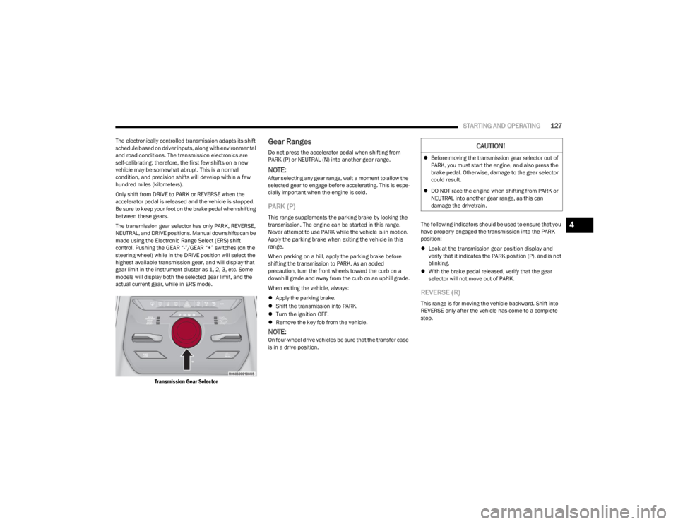
The transmission gear selector has only PARK, REVERSE,
NEUTRAL, and DRIVE positions. Manual downshifts can be
made using the Electronic Range Select (ERS) shift
control. Pushing the GEAR “-”/GEAR “+” switches (on the
steering wheel) while in the DRIVE position will select the
highest available transmission gear, and will display that
gear limit in the instrument cluster as 1, 2, 3, etc. Some
models will display both the selected gear limit, and the
actual current gear, while in ERS mode.
Transmission Gear Selector
Gear Ranges
Do not press the accelerator pedal when shifting from
PARK (P) or NEUTRAL (N) into another gear range.
NOTE:After selecting any gear range, wait a moment to allow the
selected gear to engage before accelerating. This is espe -
cially important when the engine is cold.
PARK (P)
This range supplements the parking brake by locking the
transmission. The engine can be started in this range.
Never attempt to use PARK while the vehicle is in motion.
Apply the parking brake when exiting the vehicle in this
range.
When parking on a hill, apply the parking brake before
shifting the transmission to PARK. As an added
precaution, turn the front wheels toward the curb on a
downhill grade and away from the curb on an uphill grade.
When exiting the vehicle, always:
Apply the parking brake.
Shift the transmission into PARK.
Turn the ignition OFF.
Remove the key fob from the vehicle.
NOTE:On four-wheel drive vehicles be sure that the transfer case
is in a drive position. The following indicators should be used to ensure that you
have properly engaged the transmission into the PARK
position:
Look at the transmission gear position display and
verify that it indicates the PARK position (P), and is not
blinking.
With the brake pedal released, verify that the gear
selector will not move out of PARK.
REVERSE (R)
This range is for moving the vehicle backward. Shift into
REVERSE only after the vehicle has come to a complete
stop.
CAUTION!
Before moving the transmission gear selector out of
PARK, you must start the engine, and also press the
brake pedal. Otherwise, damage to the gear selector
could result.
DO NOT race the engine when shifting from PARK or
NEUTRAL into another gear range, as this can
damage the drivetrain.
4
23_WS_OM_EN_USC_t.book Page 127
Page 130 of 396
128STARTING AND OPERATING
NEUTRAL (N)
Use this range when the vehicle is standing for prolonged
periods with the engine running. Apply the parking brake
and shift the transmission into PARK (P) if you must exit
the vehicle.
DRIVE (D)
This range should be used for most city and highway
driving. It provides the smoothest upshifts and downshifts,
and the best fuel economy. The transmission
automatically upshifts through all forward gears. When frequent transmission shifting occurs (such as
when operating the vehicle under heavy loading
conditions, in hilly terrain, traveling into strong head
winds, or while towing a heavy trailer), use the Electronic
Range Select (ERS) shift control to select a lower gear
Úpage 129. Under these conditions, using a lower gear
will improve performance and extend transmission life by
reducing excessive shifting and heat build-up.
During cold temperatures, transmission operation may be
modified depending on engine and transmission
temperature as well as vehicle speed. This feature
improves warm-up time of the engine and transmission to
achieve maximum efficiency. Engagement of the torque
converter clutch is inhibited until the transmission fluid is
warm. Normal operation will resume once the
transmission temperature has risen to a suitable level.
Transmission Limp Home Mode
Transmission function is monitored electronically for
abnormal conditions. If a condition is detected that could
result in transmission damage, Transmission Limp Home
mode is activated. In this mode, the transmission may
operate only in certain gears, or may not shift at all.
Vehicle performance may be severely degraded and the
engine may stall. In some situations, the transmission may
not re-engage if the engine is turned off and restarted. The
Malfunction Indicator Light (MIL) may be illuminated. A
message in the instrument cluster will inform the driver of
the more serious conditions, and indicate what actions
may be necessary. In the event of a momentary problem, the transmission
can be reset to regain all forward gears by performing the
following steps:
NOTE:In cases where the instrument cluster message indicates
the transmission may not re-engage after engine
shutdown, perform this procedure only in a desired
location (preferably, at an authorized dealer).
1. Stop the vehicle.
2. Shift the transmission into PARK (P), if possible.
If not, shift the transmission to NEUTRAL (N).
3. Push and hold the ignition switch until the engine turns off.
4. Wait approximately 30 seconds.
5. Restart the engine.
6. Shift into the desired gear range. If the problem is no longer detected, the transmission will return to
normal operation.
NOTE:Even if the transmission can be reset, we recommend that
you visit an authorized dealer at your earliest possible
convenience. An authorized dealer has diagnostic
equipment to assess the condition of your transmission.
If the transmission cannot be reset, authorized dealer
service is required.
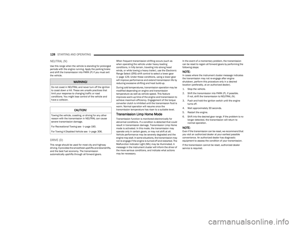
WARNING!
Do not coast in NEUTRAL and never turn off the ignition
to coast down a hill. These are unsafe practices that
limit your response to changing traffic or road
conditions. You might lose control of the vehicle and
have a collision.
CAUTION!
Towing the vehicle, coasting, or driving for any other
reason with the transmission in NEUTRAL can cause
severe transmission damage.
For Recreational Towing see
Úpage 190.
For Towing A Disabled Vehicle see
Úpage 306.
23_WS_OM_EN_USC_t.book Page 128
Page 137 of 396
STARTING AND OPERATING135
OPERATION
The indicator lamps 1 through 5 will illuminate to show the
current position of the vehicle. Flashing indicator lamps
will show a position which the system is working to
achieve. When raising, if multiple indicator lamps are
flashing while raising, the highest flashing indicator lamp
is the position the system is working to achieve. When
lowering, if multiple indicators are flashing while lowering
the lowest solid indicator lamp is the position the system
is working to achieve.
Toggle up once moves the suspension one position higher
from the current position, assuming all conditions are met
(i.e., engine running, speed below threshold, etc.). Toggle
up can be pushed multiple times. Each toggle up will raise
the requested level by one position up to a maximum
position of OR2 or the highest position allowed based on
current conditions (i.e., vehicle speed, etc.).
Toggle down once moves the suspension one position
lower from the current level, assuming all conditions are
met (i.e., engine running, doors closed, speed below
threshold, etc.). Toggle down can be pushed multiple
times. Each toggle down will lower the requested level by
one position down to a minimum of Park mode or the
lowest position allowed based on current conditions (i.e.,
vehicle speed, etc.) Automatic height changes will occur based on vehicle
speed and the current vehicle height. The indicator lamps
and instrument cluster display messages will operate the
same for automatic changes and user requested changes.
Off-Road 2 (OR2) – Indicator lamps 1 through 5 will be
illuminated.
Off-Road 1 (OR1) – Indicator lamps 2 through 5 will be
illuminated.
Normal Ride Height (NRH) – Indicator lamps 3 through
5 will be illuminated.
Aero Height – Indicator lamps 4 and 5 will be illumi -
nated.
Entry/Exit Height – Indicator lamp 5 will be illuminated.
Transport Mode – No indicator lamps will be illumi -
nated. Driving or deselecting the mode in the Uconnect
system will disable Transport mode.
Tire/Jack Mode – Indicator lamps 1 and 5 will be illumi -
nated. Driving or deselecting the mode in the Uconnect
system will disable Tire/Jack mode.
Wheel Alignment Mode – Indicator lamps 4 and 5 will
be illuminated. Driving or deselecting the mode in the
Uconnect system will disable Wheel Alignment mode.
FUEL SAVER TECHNOLOGY 5.7L AND 6.4L
ONLY — IF EQUIPPED
This feature offers improved fuel economy by shutting off
four of the engine's eight cylinders during light load and
cruise conditions. The system is automatic with no driver
inputs or additional driving skills required.
NOTE:This system may take some time to return to full function -
ality after a battery disconnect.
POWER STEERING
The electric power steering system is designed to provide
increased vehicle response and ease of maneuverability
in tight spaces. The power steering system adapts to
different driving conditions. If the electric power steering
system experiences a fault that prevents it from providing
assist, you will still have the ability to steer the vehicle
manually.
NOTE:Alternate electric power steering efforts can be selected
through the Uconnect System Úpage 197.
If the Electric Power Steering warning icon is
displayed and the “SERVICE POWER
STEERING” or the “POWER STEERING ASSIST
OFF – SERVICE SYSTEM” message is displayed
within the instrument cluster display, this indicates the
vehicle needs to be taken to an authorized dealer for
service
Úpage 108.
WARNING!
Continued operation with reduced assist could pose a
safety risk to yourself and others. Service should be
obtained as soon as possible.
4
23_WS_OM_EN_USC_t.book Page 135
Page 138 of 396

136STARTING AND OPERATING
NOTE:
Even if the power steering assistance is no longer oper -
ational, it is still possible to steer the vehicle. Under
these conditions there will be a substantial increase in
steering effort, especially at low speeds and during
parking maneuvers.
If the condition persists, see an authorized dealer for
service.
If the Steering icon is displayed and the “POWER
STEERING SYSTEM OVER TEMP” message is displayed on
the instrument cluster screen, they indicate that extreme
steering maneuvers may have occurred which caused an
over temperature condition in the electric power steering
system. Once driving conditions are safe, pull over and let
the vehicle idle for a few moments until the icon and
message turn off.
STOP/START SYSTEM — IF EQUIPPED
The Stop/Start function is developed to reduce fuel
consumption. The system will stop the engine
automatically during a vehicle stop if the required
conditions are met. Releasing the brake pedal or pressing
the accelerator pedal will automatically restart the engine
Úpage 136.
This vehicle has been upgraded with a heavy-duty starter,
enhanced battery, and other upgraded engine parts, to
handle the additional engine starts.
AUTOSTOP MODE
The Stop/Start feature is enabled after every normal
customer engine start. At that time, the system will go into
STOP/START READY and if all other conditions are met,
can go into a STOP/START AUTOSTOP ACTIVE Autostop
mode.
To Activate The Autostop Mode, The Following Must Occur:
The system must be in STOP/START READY state. A
“STOP/START READY” message will be displayed in the
instrument cluster display within the Stop/Start
section
Úpage 99.
The vehicle must be completely stopped.
The gear selector must be in a forward gear and the
brake pedal pressed.
The engine will shut down, the tachometer will move to the
zero position, and the Stop/Start telltale will illuminate
indicating you are in Autostop. Customer settings will be
maintained upon return to an engine-running condition.
POSSIBLE REASONS THE ENGINE DOES
N
OT AUTOSTOP
Prior to engine shut down, the system will check many
safety and comfort conditions to see if they are fulfilled.
Detailed information about the operation of the Stop/Start
system may be viewed in the instrument cluster display
Stop/Start Screen. In the following situations, the engine
will not stop:
Driver’s seat belt is not buckled.
Driver’s door is not closed.
Battery temperature is too warm or cold.
Battery charge is low.
The vehicle is on a steep grade.
Cabin heating or cooling is in process and an accept -
able cabin temperature has not been achieved.
HVAC is set to full defrost mode at a high blower speed.
HVAC is set to MAX A/C.
Engine has not reached normal operating temperature.
The transmission is not in a forward gear.
Hood is open.
Vehicle is in 4WD LOW, or an off-road
Selec-Terrain mode.
Brake pedal is not pressed with sufficient pressure.
Accelerator pedal input.
Engine temperature is too high.
5 mph (8 km/h) threshold has not been achieved from
previous Autostop.
Steering angle is beyond threshold.
It may be possible for the vehicle to be driven several
times without the Stop/Start system going into a
STOP/START READY state under more extreme conditions
of the items listed above.
TO START THE ENGINE WHILE IN
A
UTOSTOP MODE
While in a forward gear, the engine will start when the
brake pedal is released or the throttle pedal is pressed.
The transmission will automatically re-engage upon
engine restart.
23_WS_OM_EN_USC_t.book Page 136
Page 141 of 396
STARTING AND OPERATING139
(Continued)
USING CRUISE CONTROL ON HILLS
The transmission may downshift on hills to maintain the
vehicle set speed.
The Cruise Control system maintains speed up and down
hills. A slight speed change on moderate hills is normal.
On steep hills, a greater speed loss or gain may occur so it
may be preferable to drive without Cruise Control.
To Resume Speed
To resume a previously set speed, push the RES button
and release. Resume can be used at any speed above
20 mph (32 km/h).
To Deactivate
A tap on the brake pedal, pushing the CANC button, or
normal brake pressure while slowing the vehicle will
deactivate the Cruise Control system without erasing the
set speed from memory. The following conditions will also deactivate the Cruise
Control without erasing the set speed from memory:
Vehicle parking brake is applied
Stability event occurs
Gear selector is moved out of DRIVE
Engine overspeed occurs
Pushing the on/off button or placing the ignition in the OFF
position, will also erase the set speed from memory.
ADAPTIVE CRUISE CONTROL (ACC)
Adaptive Cruise Control (ACC) increases the driving
convenience provided by Cruise Control while traveling on
highways and major roadways. However, it is not a safety
system and not designed to prevent collisions. The Cruise
Control function performs differently
Úpage 138.
ACC will allow you to keep Cruise Control engaged in light
to moderate traffic conditions without the constant need
to reset your Cruise Control. ACC utilizes a radar sensor
and a forward facing camera designed to detect a vehicle
directly ahead of you.
NOTE:
If the ACC sensor detects a vehicle ahead, ACC will
apply limited braking or acceleration (not to exceed the
original set speed) automatically to maintain a preset
following distance, while matching the speed of the
vehicle ahead.
Any chassis/suspension or tire size modifications to
the vehicle will affect the performance of the Adaptive
Cruise Control and Forward Collision Warning system.
In vehicles NOT equipped with the Active Driving Assist
system, Fixed Speed Cruise Control (ACC not enabled)
will not detect vehicles directly ahead of you. Always be
aware of the feature selected
Úpage 382.
WARNING!
Cruise Control can be dangerous where the system
cannot maintain a constant speed. Your vehicle could
go too fast for the conditions, and you could lose control
and have an accident. Do not use Cruise Control in
heavy traffic or on roads that are winding, icy,
snow-covered or slippery.
WARNING!
Adaptive Cruise Control (ACC) is a convenience
system. It is not a substitute for active driver involve -
ment. It is always the driver’s responsibility to be
attentive of road, traffic, and weather conditions,
vehicle speed, distance to the vehicle ahead and,
most importantly, brake operation to ensure safe
operation of the vehicle under all road conditions.
Your complete attention is always required while
driving to maintain safe control of your vehicle.
Failure to follow these warnings can result in a colli -
sion and death or serious personal injury.
The ACC system:
Does not react to pedestrians, oncoming vehi -
cles, and stationary objects (e.g., a stopped
vehicle in a traffic jam or a disabled vehicle).
Cannot take street, traffic, and weather condi -
tions into account, and may be limited upon
adverse sight distance conditions.
4
23_WS_OM_EN_USC_t.book Page 139
Page 150 of 396

148STARTING AND OPERATING
Speed Limit Exceeded
When the vehicle’s speed exceeds the displayed speed
limit by 3 mph (5 km/h), the speed limit sign on the
instrument cluster display will show a red outline to alert
the driver.ACTIVE DRIVING ASSIST SYSTEM —
IF EQUIPPED
OPERATION
The Active Driving Assist (ADA) system is combined with
the Adaptive Cruise Control (ACC) system, and centers the
vehicle in the driving lane while traveling at speeds up to
90 mph (145 km/h).
For ACC system operating instructions and system
limitations, see
Úpage 139.
NOTE:
The driver should always obey traffic laws and speed
limits. Never drive above applicable speed limit restric -
tions.
The driver can override ADA at any time by braking,
accelerating, or steering the vehicle.
Just like ACC, ADA will maintain a set speed as long as the
set distance between your vehicle and the vehicle in front
is maintained. ADA will also keep your vehicle centered
between the lane lines, and monitor for other vehicles in
adjacent lanes by utilizing the Blind Spot Monitoring
sensors.
Two types of Active Driving Assist systems are available:
Base ADA system
Hands-Free ADA system
Base Active Driving Assist System — If Equipped
The Base ADA system uses sensors within the steering
wheel to measure driver attentiveness, and requires that
the driver have their hands on the steering wheel at all
times. The system will generally aim to keep the vehicle centered
in the lane, but when the driver turns the steering wheel
(e.g. to move farther away from a large vehicle in an
adjacent lane) the system will reduce its control and enter
"co-steering" mode. While in co-steering mode, the system
will provide reduced assistance and allow the driver to
control the path of the vehicle. Once the driver stops
providing input to the steering wheel, the system will
require a few seconds to fully resume lane centering
assistance, especially during curves.
Hands-Free Active Driving Assist System — If Equipped
The Hands-Free ADA system uses sensors within the
steering wheel and a driver monitoring camera located on
top of the steering column to monitor driver attentiveness.
The Hands-Free ADA system allows the driver to remove
their hands from the steering wheel when engaged, but
requires that the driver continue to pay attention to the
road.
The Hands-Free ADA system will also change lanes when
a turn signal is activated if the adjacent lane in the
direction indicated is clear of another vehicle, and lane
markings are detected (noted by a dashed line in the
direction of the available lane change). The system uses
sensors, including Blind Spot Monitoring (BSM) sensors,
to determine if a lane change is possible. If the assisted
lane change is in progress, a green arrow will appear. If a
lane change is requested but the direction indicated is not
possible, a yellow arrow will appear. Once conditions are
clear, the arrow will turn green and the assisted lane
change will begin.
CAUTION!
Functionality may be limited or the system may not
work if the sensor is obstructed.
The system may have limited operation or not work at
all in weather conditions such as heavy rain, hail, and
thick fog. Strong light contrasts can influence the
recognition capability of the sensor.
The area surrounding the sensor must not be
covered with stickers or any other object.
Do not tamper or perform any operations in the area
of the windshield glass directly surrounding the
sensor.
Clean foreign matters such as bird droppings,
insects, snow or ice on the windshield. Use specific
detergents and clean cloths to avoid scratching the
windshield.
23_WS_OM_EN_USC_t.book Page 148