torque JEEP WAGONEER 2023 User Guide
[x] Cancel search | Manufacturer: JEEP, Model Year: 2023, Model line: WAGONEER, Model: JEEP WAGONEER 2023Pages: 396, PDF Size: 15.17 MB
Page 169 of 396
STARTING AND OPERATING167
Parallel Park Exit
Enable the ParkSense Active Park Assist system by
pressing the ParkSense Active Park Assist switch. To
initiate a parking space exit maneuver, the vehicle must
be stopped, and the driver must press “Exit” on the
Uconnect display.
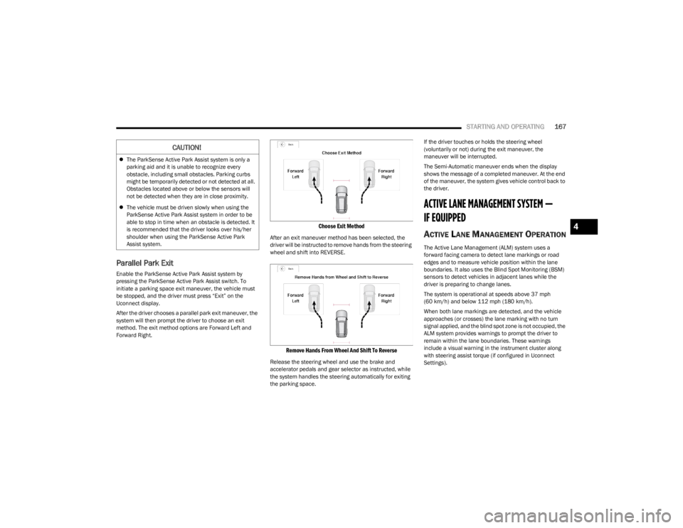
After the driver chooses a parallel park exit maneuver, the
system will then prompt the driver to choose an exit
method. The exit method options are Forward Left and
Forward Right.
Choose Exit Method
After an exit maneuver method has been selected, the
driver will be instructed to remove hands from the steering
wheel and shift into REVERSE.
Remove Hands From Wheel And Shift To Reverse
Release the steering wheel and use the brake and
accelerator pedals and gear selector as instructed, while
the system handles the steering automatically for exiting
the parking space. If the driver touches or holds the steering wheel
(voluntarily or not) during the exit maneuver, the
maneuver will be interrupted.
The Semi-Automatic maneuver ends when the display
shows the message of a completed maneuver. At the end
of the maneuver, the system gives vehicle control back to
the driver.
ACTIVE LANE MANAGEMENT SYSTEM —
IF EQUIPPED
ACTIVE LANE MANAGEMENT OPERATION
The Active Lane Management (ALM) system uses a
forward facing camera to detect lane markings or road
edges and to measure vehicle position within the lane
boundaries. It also uses the Blind Spot Monitoring (BSM)
sensors to detect vehicles in adjacent lanes while the
driver is preparing to change lanes.
The system is operational at speeds above 37 mph
(60 km/h) and below 112 mph (180 km/h).
When both lane markings are detected, and the vehicle
approaches (or crosses) the lane marking with no turn
signal applied, and the blind spot zone is not occupied, the
ALM system provides warnings to prompt the driver to
remain within the lane boundaries. These warnings
include a visual warning in the instrument cluster along
with steering assist torque (if configured in Uconnect
Settings).
CAUTION!
The ParkSense Active Park Assist system is only a
parking aid and it is unable to recognize every
obstacle, including small obstacles. Parking curbs
might be temporarily detected or not detected at all.
Obstacles located above or below the sensors will
not be detected when they are in close proximity.
The vehicle must be driven slowly when using the
ParkSense Active Park Assist system in order to be
able to stop in time when an obstacle is detected. It
is recommended that the driver looks over his/her
shoulder when using the ParkSense Active Park
Assist system.
4
23_WS_OM_EN_USC_t.book Page 167
Page 170 of 396
168STARTING AND OPERATING
If the driver crosses the lane marking, the system will
either guide the vehicle back to the center of the lane,
provide a vibration in the steering wheel, or both,
depending on radio settings.
When both lane markings are detected, and the driver
uses the turn signal to indicate a lane change, and a
vehicle is detected in the BSM zone on that side of the
vehicle, the ALM system provides a warning in the form of
steering assist and/or steering vibration (depending on
radio settings) to guide the vehicle back to the center of
the lane.
NOTE:
The system will suppress visual warnings, steering
vibration (if selected in radio settings), and steering
assistance (if selected in radio settings) when the
driver activates the turn signal, the blind spot zone is
clear of vehicles, and a lane change is occurring.
If the Blind Spot Monitoring (BSM) system detects a
vehicle in the adjacent lane, and the turn signal is
applied in that direction, the BSM LED on the mirror will
flash. If the driver continues to attempt the lane
change, steering wheel torque will be provided to keep
the vehicle within its lane markings.
The driver may manually override the steering assist
warning by applying force to the steering wheel at any
time.
When only a single lane marking is detected and the driver
drifts across the lane marking (no turn signal applied), the
Active Lane Management system provides a visual
warning in the instrument cluster, as well as a steering
assist torque (if configured in Uconnect Settings), to
prompt the driver to remain within the lane boundaries. If the driver continues to drift out of the lane, the system
provides a flashing visual warning through the instrument
cluster display as well as a haptic steering wheel vibration
(if configured in Uconnect Settings) when the vehicle
crosses the lane boundary.
NOTE:When operating conditions have been met, the Active
Lane Management system will monitor if the driver’s
hands are on the steering wheel and provides an audible
and visual warning to the driver if removed. The system
will cancel if the driver does not return their hands to the
wheel.
TURNING ACTIVE LANE MANAGEMENT
O
N OR OFF
The Active Lane Management button is located
on the switch panel on the forward part of the
center console, in front of the gear selector. To turn the system on, push the Active Lane
Management button (LED turns off). A message is
shown in the instrument cluster display.
To turn the system off, push the button again (LED turns
on.
NOTE:
The Active Lane Management system will retain the last
system state on or off from the last ignition cycle when the
ignition is placed in the ON/RUN position.
ACTIVE LANE MANAGEMENT WARNING
M
ESSAGE
The Active Lane Management system will indicate the
current lane drift condition through the instrument cluster
display.
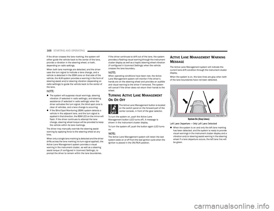
When the system is on, the lane lines are gray when both
of the lane boundaries have not been detected.
System On (Gray Lines)
Left Lane Departure — Only Left Lane Detected
When the system is on and only the left lane marking
has been detected, and the system is ready to provide
visual warnings in the instrument cluster display and a
vibration and/or steering assist warning in the steering
wheel if a lane departure occurs, the left lane line will
be green.
23_WS_OM_EN_USC_t.book Page 168
Page 171 of 396
STARTING AND OPERATING169
When the system senses the lane line has been
approached (but not crossed), the left lane line will
change to solid yellow and the system will provide
steering assist torque (if programmed in Uconnect
Settings).
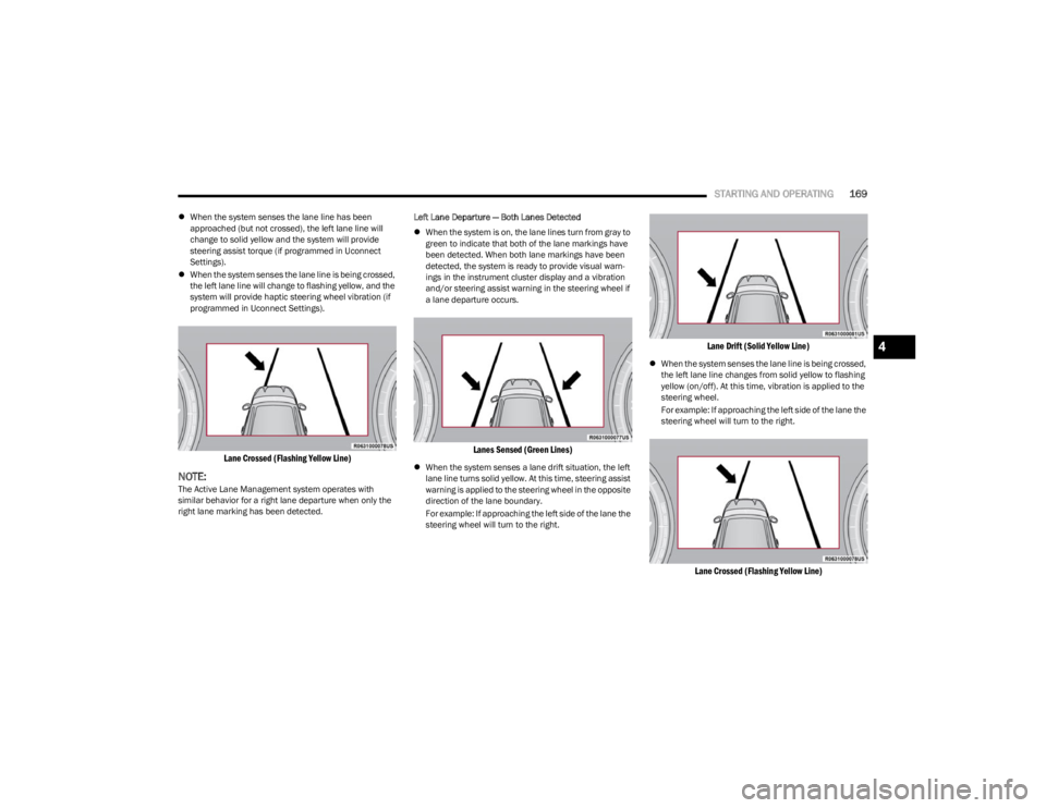
When the system senses the lane line is being crossed,
the left lane line will change to flashing yellow, and the
system will provide haptic steering wheel vibration (if
programmed in Uconnect Settings).
Lane Crossed (Flashing Yellow Line)
NOTE:The Active Lane Management system operates with
similar behavior for a right lane departure when only the
right lane marking has been detected. Left Lane Departure — Both Lanes Detected
When the system is on, the lane lines turn from gray to
green to indicate that both of the lane markings have
been detected. When both lane markings have been
detected, the system is ready to provide visual warn -
ings in the instrument cluster display and a vibration
and/or steering assist warning in the steering wheel if
a lane departure occurs.
Lanes Sensed (Green Lines)
When the system senses a lane drift situation, the left
lane line turns solid yellow. At this time, steering assist
warning is applied to the steering wheel in the opposite
direction of the lane boundary.
For example: If approaching the left side of the lane the
steering wheel will turn to the right.
Lane Drift (Solid Yellow Line)
When the system senses the lane line is being crossed,
the left lane line changes from solid yellow to flashing
yellow (on/off). At this time, vibration is applied to the
steering wheel.
For example: If approaching the left side of the lane the
steering wheel will turn to the right.
Lane Crossed (Flashing Yellow Line)
4
23_WS_OM_EN_USC_t.book Page 169
Page 172 of 396
170STARTING AND OPERATING
NOTE:
The Active Lane Management system operates with
similar behavior for a right lane departure.
If the turn signal is activated, and the vehicle begins to
depart the lane at the same time the Blind Spot Moni -
toring (BSM) system detects another vehicle in the
BSM zones, the system will provide haptic steering
wheel vibration and/or steering assist torque (if
programmed in Uconnect Settings).
CHANGING ACTIVE LANE MANAGEMENT
S
TATUS
Configurable settings for the Active Lane Management
system are available within the Uconnect system
Úpage 197.
Selectable Warning Types:
Vibration Only
Steering Assist Only
Vibration And Steering Assist
Other configurable settings for this system are for the
intensity of the vibration (high/med/low), steering assist
strength (hi/med/low), and the warning zone sensitivity
(early/medium/late).
NOTE:
The system will not apply vibration and/or steering
assist to the steering wheel whenever a safety system
engages (Anti-Lock Brakes, Traction Control System,
Electronic Stability Control, Forward Collision Warning,
etc.).
The Blind Spot Monitoring system will be forced on
when the ALM system is enabled.
The ALM system will be suppressed when the Active
Driving Assist system (if equipped) is engaged.
PARKVIEW REAR BACK UP CAMERA
Your vehicle is equipped with the ParkView Rear Back Up
Camera that allows you to see an on-screen image of the
rear surroundings of your vehicle whenever the gear
selector is put into REVERSE. The image will be displayed
on the Navigation/Multimedia radio display screen along
with a caution note to “Check Entire Surroundings” across
the top of the screen. After five seconds this note will
disappear. The ParkView camera is located on the rear of
the vehicle above the rear license plate.
When the vehicle is shifted out of REVERSE with camera
delay turned off, the rear camera mode is exited and the
previous screen appears.
Manual Activation Of The Back Up Camera
1. Press the Vehicle button located on the bottom of
the Uconnect display and then select the Controls
menu.
2. Press the Back Up Camera icon to turn the Rear View Camera system on.
NOTE:
The Rear View camera can also be turned on manually
through the Apps menu within the Uconnect system.
The ParkView Rear Back Up Camera has program -
mable modes of operation that may be selected
through the Uconnect system
Úpage 197. When the vehicle is shifted out of REVERSE with camera
delay turned off, the rear camera mode is exited and the
previous screen appears. When the vehicle is shifted out
of REVERSE with camera delay turned on, the camera
image will continue to be displayed for up to 10 seconds
unless the following conditions occur: the vehicle speed
exceeds 8 mph (13 km/h), the vehicle is shifted into
PARK, the vehicle’s ignition is placed in the OFF position,
or the touchscreen X button to disable the display of the
Rear View Camera is pressed.
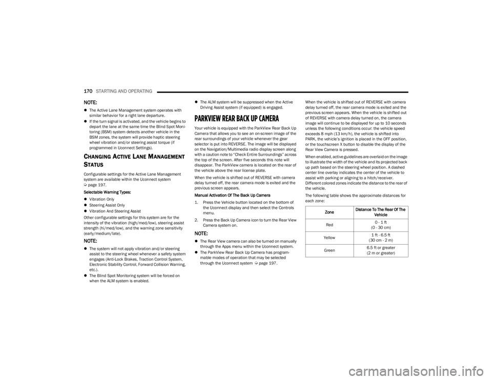
When enabled, active guidelines are overlaid on the image
to illustrate the width of the vehicle and its projected back
up path based on the steering wheel position. A dashed
center line overlay indicates the center of the vehicle to
assist with parking or aligning to a hitch/receiver.
Different colored zones indicate the distance to the rear of
the vehicle.
The following table shows the approximate distances for
each zone:
Zone Distance To The Rear Of The
Vehicle
Red 0 - 1 ft
(0 - 30 cm)
Yellow 1 ft - 6.5 ft
(30 cm - 2 m)
Green 6.5 ft or greater
(2 m or greater)
23_WS_OM_EN_USC_t.book Page 170
Page 197 of 396
STARTING AND OPERATING195
If you stall or begin to lose forward motion while climbing
a steep hill, allow your vehicle to come to a stop and
immediately apply the brakes. Restart the engine, and
shift into REVERSE (R). Back slowly down the hill, allowing
the compression braking of the engine to help regulate
your speed. If the brakes are required to control vehicle
speed, apply them lightly and avoid locking or skidding the
tires.
Remember, never drive diagonally across a hill. Always
drive straight up or down.
If the wheels start to slip as you approach the crest of a
hill, ease off the accelerator and maintain forward motion
by turning the front wheels slowly. This may provide a fresh
“bite” into the surface and will usually provide traction to
complete the climb.Traction Downhill
When descending mountains or hills, use Hill Descent
Control or Selec-Speed Control to avoid repeated heavy
braking.
If not equipped with Hill Descent Control or Selec-Speed
Control use the following procedure:
Shift the transmission into a low gear, and the transfer
case into 4WD LOW range. Let the vehicle go slowly down
the hill with all four wheels turning against engine
compression drag. This will permit you to control the
vehicle speed and direction.
When descending mountains or hills, repeated braking
can cause brake fade with loss of braking control. Avoid
repeated heavy braking by downshifting the transmission
whenever possible.
After Driving Off-Road
Off-road operation puts more stress on your vehicle than
does most on-road driving. After going off-road, it is always
a good idea to check for damage. That way you can get any
problems taken care of right away and have your vehicle
ready when you need it.
Completely inspect the underbody of your vehicle.
Check tires, body structure, steering, suspension, and
exhaust system for damage.
Inspect the radiator for mud and debris and clean as
required.
Check threaded fasteners for looseness, particularly
on the chassis, drivetrain components, steering, and
suspension. Retighten them, if required, and torque to
the values specified in the Service Manual.
Check for accumulations of plants or brush. These
things could be a fire hazard. They might hide damage
to fuel lines, brake hoses, axle pinion seals, and
propeller shafts.
After extended operation in mud, sand, water, or
similar dirty conditions, have the radiator, fan, brake
rotors, wheels, brake linings, and axle yokes inspected
and cleaned as soon as possible.
If you experience unusual vibration after driving in
mud, slush or similar conditions, check the wheels for
impacted material. Impacted material can cause a
wheel imbalance and freeing the wheels of it will
correct the situation.
WARNING!
If the engine stalls, you lose forward motion, or cannot
make it to the top of a steep hill or grade, never attempt
to turn around. To do so may result in tipping and rolling
the vehicle. Always back carefully straight down a hill in
REVERSE gear. Never back down a hill in NEUTRAL
using only the brake.
WARNING!
Abrasive material in any part of the brakes may cause
excessive wear or unpredictable braking. You might not
have full braking power when you need it to prevent a
collision. If you have been operating your vehicle in dirty
conditions, get your brakes checked and cleaned as
necessary.
4
23_WS_OM_EN_USC_t.book Page 195
Page 243 of 396
SAFETY241
ELECTRONIC BRAKE CONTROL (EBC)
S
YSTEM
Your vehicle is equipped with an advanced EBC system.
This system includes the Anti-Lock Brake System (ABS),
Brake Assist System (BAS), Electronic Brake Force
Distribution (EBD), Electronic Stability Control (ESC),
Electronic Roll Mitigation (ERM), Hill Start Assist (HSA),
Intersection Collision Assist (ICA), and Traction Control
System (TCS). These systems work together to enhance
both vehicle stability and control in various driving
conditions.
Your vehicle may also be equipped with Dynamic Steering
Torque (DST), Rain Brake Support (RBS), Ready Alert
Braking (RAB), and Trailer Sway Control (TSC).
Brake Assist System (BAS)
The BAS is designed to optimize the vehicle’s braking
capability during emergency braking maneuvers. The
system detects an emergency braking situation by sensing
the rate and amount of brake application and then applies
optimum pressure to the brakes. This can help reduce
braking distances. The BAS complements the Anti-Lock
Brake System (ABS). Applying the brakes very quickly
results in the best BAS assistance. To receive the benefit
of the system, you must apply continuous braking
pressure during the stopping sequence (do not “pump”
the brakes). Do not reduce brake pedal pressure unless
braking is no longer desired. Once the brake pedal is
released, the BAS is deactivated.
Brake System Warning Light
The red Brake System Warning Light will turn on when the
ignition is placed in the ON/RUN mode and may stay on for
as long as four seconds.
If the Brake System Warning Light remains on or comes on
while driving, it indicates that the brake system is not
functioning properly and that immediate service is
required. If the Brake System Warning Light does not
come on when the ignition is placed in the ON/RUN mode,
have the light repaired as soon as possible.
Electronic Brake Force Distribution (EBD)
EBD manages the distribution of the braking torque
between the front and rear axles by limiting braking
pressure to the rear axle. This is done to prevent
overslip of the rear wheels to avoid vehicle instability, and
to prevent the rear axle from entering ABS before the
front axle.
Electronic Roll Mitigation (ERM)
ERM anticipates the potential for wheel lift by monitoring
the driver’s steering wheel input and the speed of the
vehicle. When ERM determines that the rate of change of
the steering wheel angle and vehicle’s speed are
sufficient to potentially cause wheel lift, it then applies the
appropriate brake and may also reduce engine power to
lessen the chance that wheel lift will occur. ERM can only
reduce the chance of wheel lift occurring during severe or
evasive driving maneuvers; it cannot prevent wheel lift
due to other factors, such as road conditions, leaving the
roadway, or striking objects or other vehicles.
NOTE:
ERM is disabled any time the ESC is in “Full Off” mode (if
equipped). See
Úpage 242 for a complete explanation of
the available ESC modes.
WARNING!
The Brake Assist System (BAS) cannot prevent the
natural laws of physics from acting on the vehicle, nor
can it increase the traction afforded by prevailing road
conditions. BAS cannot prevent collisions, including
those resulting from excessive speed in turns, driving
on very slippery surfaces, or hydroplaning. The
capabilities of a BAS-equipped vehicle must never be
exploited in a reckless or dangerous manner, which
could jeopardize the user's safety or the safety of
others.
WARNING!
Many factors, such as vehicle loading, road conditions
and driving conditions, influence the chance that wheel
lift or rollover may occur. ERM cannot prevent all wheel
lift or rollovers, especially those that involve leaving the
roadway or striking objects or other vehicles. The
capabilities of an ERM-equipped vehicle must never be
exploited in a reckless or dangerous manner which
could jeopardize the user's safety or the safety of
others.
6
23_WS_OM_EN_USC_t.book Page 241
Page 247 of 396
SAFETY245
Disabling And Enabling HSA
This feature can be turned on or turned off. To change the
current setting, proceed as follows:
If disabling HSA using your instrument cluster display,
see
Úpage 99 for further information.
If disabling HSA using Uconnect Settings, see
Úpage 197 for further information.
Towing With HSA
HSA will also provide assistance to mitigate roll back while
towing a trailer.
Rain Brake Support (RBS)
RBS may improve braking performance in wet conditions.
It will periodically apply a small amount of brake pressure
to remove any water buildup on the front brake rotors. It
functions when the windshield wipers are in LO or HI
speed. When RBS is active, there is no notification to the
driver and no driver interaction is required.
Ready Alert Braking (RAB)
RAB may reduce the time required to reach full braking
during emergency braking situations. It anticipates when
an emergency braking situation may occur by monitoring
how fast the throttle is released by the driver. The
Electronic Brake Controller (EBC) will prepare the brake
system for a panic stop.
Selec-Speed Control (SSC) — If Equipped
Selec-Speed Control (SSC) is intended for
off-road driving in 4WD Low only. SSC
maintains vehicle speed by actively controlling
engine torque and brakes.
SSC has three states:
1. Off (feature is not enabled and will not activate)
2. Enabled (feature is enabled and ready but activation conditions are not met, or driver is actively overriding
with brake or throttle application)
3. Active (feature is enabled and actively controlling vehicle speed)
Enabling SSC
SSC is enabled by pushing the SSC switch, but the
following conditions must also be met to enable SSC:
The driveline is in 4WD Low.
The vehicle speed is below 5 mph (8 km/h).
The parking brake is released.
The driver door is closed.
The driver is not applying throttle.
Activating SSC
Once SSC is enabled it will activate automatically once the
following conditions are met:
Driver releases throttle.
Driver releases brake.
Transmission is in any selection other than PARK.
Vehicle speed is below 20 mph (32 km/h).WARNING!
There may be situations where the Hill Start Assist
(HSA) will not activate and slight rolling may occur, such
as on minor hills or with a loaded vehicle, or while
pulling a trailer. HSA is not a substitute for active driving
involvement. It is always the driver’s responsibility to be
attentive to distance to other vehicles, people, and
objects, and most importantly brake operation to
ensure safe operation of the vehicle under all road
conditions. Your complete attention is always required
while driving to maintain safe control of your vehicle.
Failure to follow these warnings can result in a collision
or serious personal injury.
WARNING!
If you use a trailer brake controller with your trailer,
the trailer brakes may be activated and deactivated
with the brake switch. If so, there may not be enough
brake pressure to hold both the vehicle and the
trailer on a hill when the brake pedal is released. In
order to avoid rolling down an incline while resuming
acceleration, manually activate the trailer brake or
apply more vehicle brake pressure prior to releasing
the brake pedal.
HSA is not a parking brake. Always apply the parking
brake fully when exiting your vehicle. Also, be certain
to place the transmission in PARK.
Failure to follow these warnings can result in a colli -
sion or serious personal injury.
6
23_WS_OM_EN_USC_t.book Page 245
Page 291 of 396
SAFETY289
PERIODIC SAFETY CHECKS YOU SHOULD
M
AKE OUTSIDE THE VEHICLE
Tires
Examine tires for excessive tread wear and uneven wear
patterns. Check for stones, nails, glass, or other objects
lodged in the tread or sidewall. Inspect the tread for cuts
and cracks. Inspect sidewalls for cuts, cracks, and bulges.
Check the lug nut/bolt torque for tightness. Check the
tires (including spare) for proper cold inflation pressure.
Lights
Have someone observe the operation of brake lights and
exterior lights while you work the controls. Check turn
signal and high beam indicator lights on the instrument
panel.
Door Latches
Check for proper closing, latching, and locking.
Fluid Leaks
Check area under the vehicle after overnight parking for
fuel, coolant, oil, or other fluid leaks. Also, if gasoline
fumes are detected or if fuel or brake fluid leaks are
suspected, the cause should be located and corrected
immediately.
EXHAUST GAS
The best protection against carbon monoxide entry into
the vehicle body is a properly maintained engine exhaust
system. Whenever a change is noticed in the sound of the exhaust
system, when exhaust fumes can be detected inside the
vehicle, or when the underside or rear of the vehicle is
damaged, have an authorized dealer inspect the complete
exhaust system and adjacent body areas for broken,
damaged, deteriorated, or mispositioned parts. Open
seams or loose connections could permit exhaust fumes
to seep into the passenger compartment. In addition,
inspect the exhaust system each time the vehicle is raised
for lubrication or oil change. Replace as required.
CARBON MONOXIDE WARNINGS
WARNING!
Exhaust gases can injure or kill. They contain carbon
monoxide (CO), which is colorless and odorless.
Breathing it can make you unconscious and can
eventually poison you. To avoid breathing (CO), follow
these safety tips:
Do not run the engine in a closed garage or in
confined areas any longer than needed to move your
vehicle in or out of the area.
If you are required to drive with the trunk/liftgate/
rear doors open, make sure that all windows are
closed and the climate control BLOWER switch is set
at high speed. DO NOT use the recirculation mode.
If it is necessary to sit in a parked vehicle with the
engine running, adjust your heating or cooling
controls to force outside air into the vehicle. Set the
blower at high speed.
WARNING!
Carbon monoxide (CO) in exhaust gases is deadly.
Follow the precautions below to prevent carbon
monoxide poisoning:
Do not inhale exhaust gases. They contain carbon
monoxide, a colorless and odorless gas, which can
kill. Never run the engine in a closed area, such as a
garage, and never sit in a parked vehicle with the
engine running for an extended period. If the vehicle
is stopped in an open area with the engine running
for more than a short period, adjust the ventilation
system to force fresh, outside air into the vehicle.
Guard against carbon monoxide with proper mainte -
nance. Have the exhaust system inspected every
time the vehicle is raised. Have any abnormal condi -
tions repaired promptly. Until repaired, drive with all
side windows fully open.
6
23_WS_OM_EN_USC_t.book Page 289
Page 301 of 396
IN CASE OF EMERGENCY299
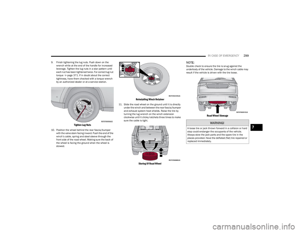
9. Finish tightening the lug nuts. Push down on the
wrench while at the end of the handle for increased
leverage. Tighten the lug nuts in a star pattern until
each nut has been tightened twice. For correct lug nut
torque
Úpage 371. If in doubt about the correct
tightness, have them checked with a torque wrench
by an authorized dealer or at a service station.
Tighten Lug Nuts
10. Position the wheel behind the rear fascia/bumper with the valve stem facing inward. Push the end of the
winch’s cable, spring and steel sleeve through the
front side of the road wheel. Making sure the back of
the wheel is facing the ground when the wheel is
stowed.
Reinstalling Winch Retainer
11. Slide the road wheel on the ground until it is directly under the winch and between the rear fascia/bumper
and exhaust system heat shields. Raise the tire by
turning the lug wrench on the winch extension
clockwise until it clicks/ratchets three times to make
sure the cable is tight.
Storing Of Road Wheel
NOTE:Double check to ensure the tire is snug against the
underbody of the vehicle. Damage to the winch cable may
result if the vehicle is driven with the tire loose.
Road Wheel Stowage
WARNING!
A loose tire or jack thrown forward in a collision or hard
stop could endanger the occupants of the vehicle.
Always stow the jack parts and the spare tire in the
places provided. Have the deflated (flat) tire repaired or
replaced immediately.7
23_WS_OM_EN_USC_t.book Page 299
Page 302 of 396

300IN CASE OF EMERGENCY
12. Lower the jack to the fully closed position.
13. Return the Jack and tools back into the jack storage
bin. Reinstall the jack storage cover by firmly pushing
down until the clips lock into position.
14. After 25 miles (40 km), check the lug nut torque with a torque wrench to ensure that all lug nuts are
properly seated against the wheel.
15. Have the road wheel and tire repaired as soon as possible and properly secure the spare tire, jack and
tool kit.
NOTE:Do not drive with the spare tire installed for more than
50 miles (80 km) at a max speed of 50 mph (80 km/h).
JUMP STARTING
If your vehicle has a discharged battery, it can be jump
started using a set of jumper cables and a battery in
another vehicle, or by using a portable battery booster
pack. Jump starting can be dangerous if done improperly,
so please follow the procedures in this section carefully.
NOTE:When using a portable battery booster pack, follow the
manufacturer's operating instructions and precautions.
PREPARATIONS FOR JUMP START
The battery in your vehicle is located in the front of the
engine compartment, behind the left headlight assembly.
Positive (+) Jump Starting Post
NOTE:The positive (+) battery post may be covered with a
protective cap. Lift up on the cap to gain access to the
positive battery post. Do not jump off fuses. Only jump
directly off positive post which has a positive (+) symbol on
or around the post.
See the following steps to prepare for jump starting:
1. Apply the parking brake, shift the automatic transmission into PARK (P) and turn the ignition OFF.
2. Turn off the heater, radio, and all electrical accessories.
3. If using another vehicle to jump start the battery, park the vehicle within the jumper cables’ reach, apply the
parking brake and make sure the ignition is OFF.
NOTE:Be sure that the disconnected cable ends do not touch
each other, or either vehicle, until properly connected for
jump starting.
WARNING!
Do not attempt jump starting if the battery is frozen. It
could rupture or explode and cause personal injury.
CAUTION!
Do not use a portable battery booster pack or any other
booster source with a system voltage greater than
12 Volts or damage to the battery, starter motor,
alternator or electrical system may occur.
WARNING!
Do not allow vehicles to touch each other as this could
establish a ground connection and personal injury
could result.
23_WS_OM_EN_USC_t.book Page 300