driver settings JEEP WAGONEER 2023 Owner's Manual
[x] Cancel search | Manufacturer: JEEP, Model Year: 2023, Model line: WAGONEER, Model: JEEP WAGONEER 2023Pages: 396, PDF Size: 15.17 MB
Page 106 of 396
104GETTING TO KNOW YOUR INSTRUMENT PANEL
INSTRUMENT CLUSTER DISPLAY MENU
I
TEMS
The instrument cluster display can be used to view the
main menu items for several features. Use the up and
down arrow buttons to scroll through the driver
interactive display menu options until the desired menu is
reached.
NOTE:Depending on the vehicle’s options, feature settings may
vary.
Main Menu
DRIVER INFO
Push and release the up or down arrow button until
the Driver Info icon/title is highlighted in the instrument
cluster display. Push the left or right arrow button to
scroll through the information submenus.
Speedometer
Push and release the OK button to toggle units (mph or
km/h) of the speedometer. Hold the OK button to toggle
between Analog and Digital speedometer. Night Vision — If Equipped
Arrow buttons and submenu indicators
disappear after five seconds of menu
navigation inactivity. Pedestrian/Animal icons
will be displayed in the top left location
Úpage 172.
Driver Assist — If Equipped
The Driver Assist screen indicates the current status of
ACC, Active Lane Management and Active Driving Assist/
Assist+/Pilot
Úpage 247.
VEHICLE INFO
Push and release the up or down arrow button until
the Vehicle Info icon/title is highlighted in the instrument
cluster display. Push the left or right arrow button to
scroll through the information submenus.
Fuel Economy
Average Fuel Economy
Current Fuel Economy
Range To Empty
Press the OK button to reset the average fuel economy
NOTE:The Range feature is not able to be reset through the
instrument cluster display controls. Gauge Summary
Coolant Temperature — If Equipped
Displays the current temperature of the coolant.
Transmission Temperature
Displays the actual transmission temperature.
Oil Temperature
Displays the actual oil temperature.
Oil Pressure
Displays the actual oil pressure.
Battery Voltage
Displays the current voltage level of the battery.
Oil Life
Displays the current oil life of the vehicle.
Tire Pressure Monitoring System
If tire pressure is OK for all tires a vehicle icon is
displayed with tire pressure values in each corner of
the icon.
If one or more tires have low pressure, “Inflate Tire To
XX” is displayed with the vehicle icon and the tire pres -
sure values in each corner of the icon with the pressure
value of the low tire are displayed in a different color
than the other tire pressure value.
If the Tire Pressure system requires service, “Service
Tire Pressure System” is displayed.
Tire Pressure is an information only function, and cannot
be reset
Úpage 252.
Stop/Start Status — If Equipped
Display current status of Stop/Start system.
23_WS_OM_EN_USC_t.book Page 104
Page 108 of 396
106GETTING TO KNOW YOUR INSTRUMENT PANEL
Screen Setup
Push and release the up or down arrow button
until the Settings Menu icon/title is highlighted in the
instrument cluster display. Push and release the OK
button to enter the submenus and follow the prompts on
the screen as needed. The Settings feature allows you to
change what information is displayed in the instrument
cluster as well as the location that information is
displayed. Current Gear
On
Off
Odometer
Show
Hide
NOTE:Menus with (show/hide) can push the OK button to
choose whether to show or hide this menu on the
instrument cluster display.
Defaults (Restores All Settings To Default Settings)
Restore
Cancel
HEAD UP DISPLAY (HUD) —
I
F EQUIPPED
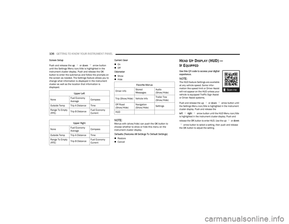
Use this QR code to access your digital
experience .
NOTE:The HUD feature Settings are available
at any vehicle speed. Some infor -
mation like speed limit or Driver Assist
will not appear on the HUD unless your
vehicle is equipped Traffic Sign Assist
or Driver Assist systems.
Push and release the
up
or
down
arrow button until
the Settings Menu icon/title is highlighted in the instrument
cluster display. Push and release the
left
right
arrow button until the HUD Menu icon/title
is highlighted in the instrument cluster display. Push and
release the
OK
button to enter HUD. Use the
up
or
down
arrow button to select a setting, then push and release
the
OK
button to adjust the setting.
Upper Left
None Fuel Economy
AverageCompass
Outside Temp Trip A Distance Time
Range To Empty
(RTE) Trip B DistanceFuel Economy
Current
Upper Right
None Fuel Economy
AverageCompass
Outside Temp Trip A Distance Time
Range To Empty
(RTE) Trip B DistanceFuel Economy
CurrentFavorite Menus
Driver info Stored
MessagesAudio
(Show/Hide)
Trip (Show/Hide) Vehicle Info Trailer Tow
(Show/Hide)
Off Road
(Show/Hide) Navigation
(Show/Hide)
Settings
HUD
23_WS_OM_EN_USC_t.book Page 106
Page 109 of 396
GETTING TO KNOW YOUR INSTRUMENT PANEL107
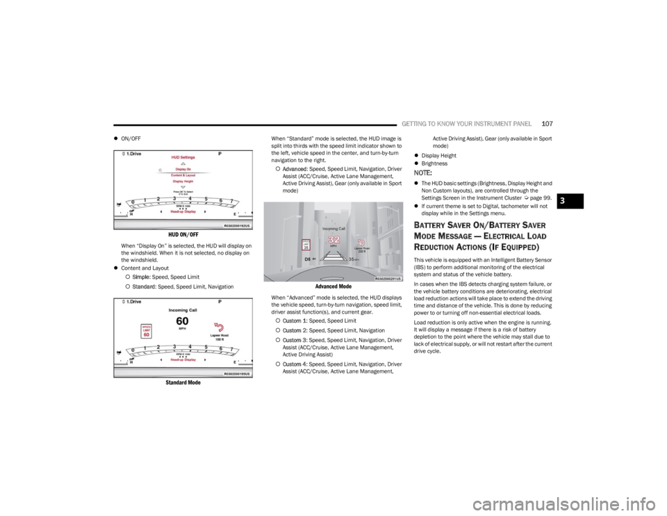
ON/OFF
HUD ON/OFF
When “Display On” is selected, the HUD will display on
the windshield. When it is not selected, no display on
the windshield.
Content and Layout
Simple : Speed, Speed Limit
Standard : Speed, Speed Limit, Navigation
Standard Mode
When “Standard” mode is selected, the HUD image is
split into thirds with the speed limit indicator shown to
the left, vehicle speed in the center, and turn-by-turn
navigation to the right.
Advanced : Speed, Speed Limit, Navigation, Driver
Assist (ACC/Cruise, Active Lane Management,
Active Driving Assist), Gear (only available in Sport
mode)
Advanced Mode
When “Advanced” mode is selected, the HUD displays
the vehicle speed, turn-by-turn navigation, speed limit,
driver assist function(s), and current gear.
Custom 1 : Speed, Speed Limit
Custom 2 : Speed, Speed Limit, Navigation
Custom 3 : Speed, Speed Limit, Navigation, Driver
Assist (ACC/Cruise, Active Lane Management,
Active Driving Assist)
Custom 4 : Speed, Speed Limit, Navigation, Driver
Assist (ACC/Cruise, Active Lane Management, Active Driving Assist), Gear (only available in Sport
mode)
Display Height
Brightness
NOTE:
The HUD basic settings (Brightness, Display Height and
Non Custom layouts), are controlled through the
Settings Screen in the Instrument Cluster
Úpage 99.
If current theme is set to Digital, tachometer will not
display while in the Settings menu.
BATTERY SAVER ON/BATTERY SAVER
M
ODE MESSAGE — ELECTRICAL LOAD
R
EDUCTION ACTIONS (IF EQUIPPED)
This vehicle is equipped with an Intelligent Battery Sensor
(IBS) to perform additional monitoring of the electrical
system and status of the vehicle battery.
In cases when the IBS detects charging system failure, or
the vehicle battery conditions are deteriorating, electrical
load reduction actions will take place to extend the driving
time and distance of the vehicle. This is done by reducing
power to or turning off non-essential electrical loads.
Load reduction is only active when the engine is running.
It will display a message if there is a risk of battery
depletion to the point where the vehicle may stall due to
lack of electrical supply, or will not restart after the current
drive cycle.
3
23_WS_OM_EN_USC_t.book Page 107
Page 126 of 396
124STARTING AND OPERATING
If exceptional circumstances should make it necessary to
engage the parking brake while the vehicle is in motion,
maintain upward pressure on the EPB switch for as long as
engagement is desired. The Brake Warning Light will
illuminate, and a continuous chime will sound. The rear
stop lamps will also be illuminated automatically while the
vehicle remains in motion.
To disengage the parking brake while the vehicle is in
motion, release the switch. If the vehicle is brought to a
complete stop using the parking brake, when the vehicle
reaches approximately 3 mph (5 km/h), the parking brake
will remain engaged. In the unlikely event of a malfunction of the EPB system, a
yellow EPB Warning Light will illuminate. This may be
accompanied by the Brake Warning Light flashing. In this
event, urgent service of the EPB system is required. Do not
rely on the parking brake to hold the vehicle stationary.
Auto Park Brake
The EPB can be programmed to be applied automatically
whenever the vehicle is at a standstill and the
transmission is placed in PARK. Auto Park Brake is
enabled and disabled by customer selection through the
customer programmable features section of the Uconnect
Settings
Úpage 211.
Any single Auto Park Brake application can be bypassed by
pushing the EPB switch to the release position while the
transmission is placed in PARK.
SafeHold
SafeHold is a safety feature of the EPB system that will
engage the parking brake automatically if the vehicle is
left unsecured while the ignition is in ON/RUN.
The parking brake will automatically engage if all of the
following conditions are met:
The vehicle is at a standstill.
There is no attempt to press the brake pedal or accel -
erator pedal.
The seat belt is unbuckled.
The driver’s door is open. SafeHold can be temporarily bypassed by pushing the EPB
switch while the driver’s door is open. Once manually
bypassed, SafeHold will be enabled again once the vehicle
reaches 12 mph (20 km/h) or the ignition is turned to the
OFF position and back to ON again.
Auto Hold — If Equipped
Auto Hold is a comfort feature that allows the driver to
remove their foot from the brake pedal once the vehicle
has come to a stop. The vehicle must be held at a
standstill for a predetermined amount of time by hydraulic
braking. The EPB will then engage and continue to hold
the vehicle at a stop until the driver applies the accelerator
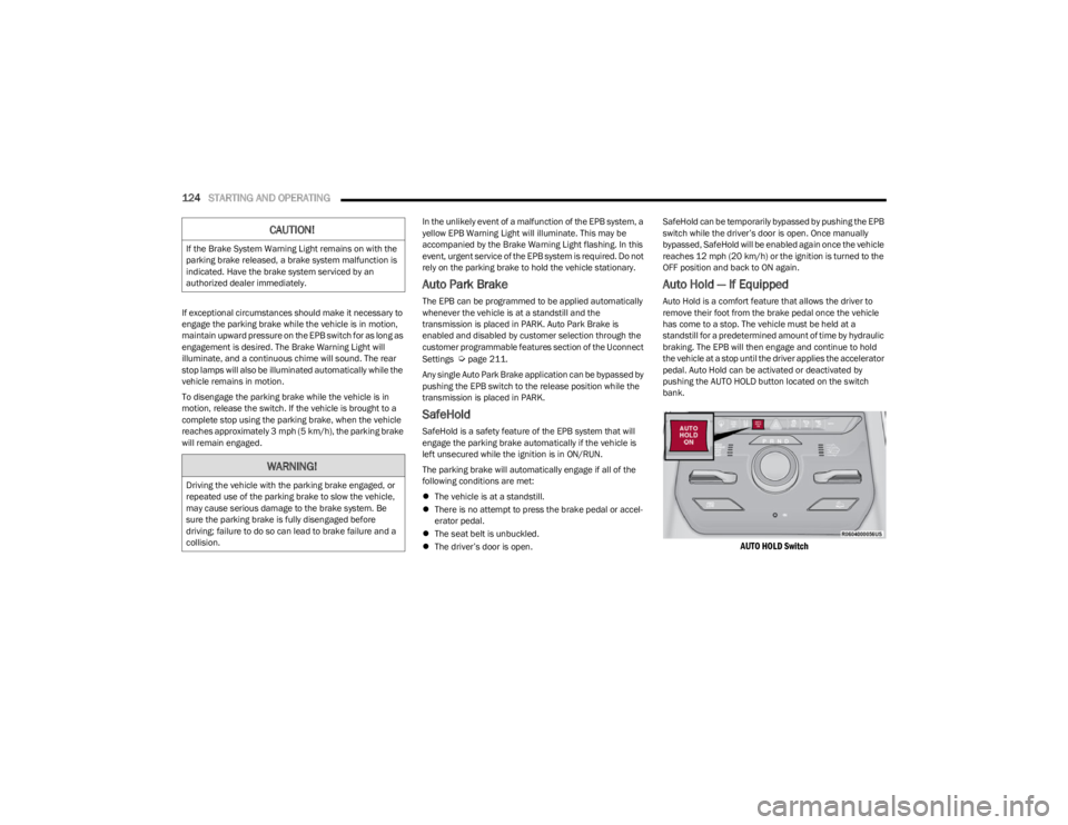
pedal. Auto Hold can be activated or deactivated by
pushing the AUTO HOLD button located on the switch
bank.
AUTO HOLD Switch
CAUTION!
If the Brake System Warning Light remains on with the
parking brake released, a brake system malfunction is
indicated. Have the brake system serviced by an
authorized dealer immediately.
WARNING!
Driving the vehicle with the parking brake engaged, or
repeated use of the parking brake to slow the vehicle,
may cause serious damage to the brake system. Be
sure the parking brake is fully disengaged before
driving; failure to do so can lead to brake failure and a
collision.
23_WS_OM_EN_USC_t.book Page 124
Page 127 of 396
STARTING AND OPERATING125
(Continued)
The following conditions must be met for Auto Hold to
activate:
Driver’s door is closed
Driver's seat belt is fastened
Vehicle is at a standstill
Forward gear is selected
ACC is not engaged
EPB is not applied
ParkSense Active Park Assist System auto parking
maneuver is not activated
Brake Maintenance Mode
We recommend having your brakes serviced by an
authorized dealer. You should only make repairs for which
you have the knowledge and the right equipment. You
should only enter Brake Maintenance mode during brake
service.
When servicing your rear brakes, it may be necessary for
you or your technician to push the rear piston into the rear
caliper bore. With the EPB system, this can only be done
after retracting the EPB actuator. Fortunately, actuator
retraction can be done easily by entering the Brake
Maintenance mode through the Uconnect Settings in your
vehicle. This menu-based system will guide you through
the steps necessary to retract the EPB actuator in order to
perform rear brake service. Maintenance mode has requirements that must be met in
order to be activated:
The vehicle must be at a standstill.
The parking brake must be unapplied.
The transmission must be in PARK or NEUTRAL.
While in Maintenance mode, the EPB Warning Light will
flash continuously while the ignition is ON.
When brake service work is complete, the following steps
must be followed to reset the parking brake system to
normal operation:
Ensure the vehicle is at a standstill.
Press the brake pedal with moderate force.
Apply the EPB switch.
AUTOMATIC TRANSMISSION
You must press and hold the brake pedal while shifting out
of PARK.
WARNING!
You can be badly injured working on or around a motor
vehicle. Do only that service work for which you have
the knowledge and the right equipment. If you have any
doubt about your ability to perform a service job, take
your vehicle to a competent mechanic.
WARNING!
Never use the PARK (P) position as a substitute for
the parking brake. Always apply the parking brake
fully when exiting the vehicle to guard against vehicle
movement and possible injury or damage.
Your vehicle could move and injure you and others if
it is not in PARK. Check by trying to move the trans -
mission gear selector out of PARK with the brake
pedal released. Make sure the transmission is in
PARK before exiting the vehicle.
The transmission may not engage PARK if the vehicle
is moving. Always bring the vehicle to a complete
stop before shifting to PARK, and verify that the
transmission gear position indicator solidly indicates
PARK without blinking. Ensure that the vehicle is
completely stopped, and the PARK position is prop -
erly indicated, before exiting the vehicle.
It is dangerous to shift out of PARK or NEUTRAL (N) if
the engine speed is higher than idle speed. If your
foot is not firmly pressing the brake pedal, the
vehicle could accelerate quickly forward or in
reverse. You could lose control of the vehicle and hit
someone or something. Only shift into gear when the
engine is idling normally and your foot is firmly
pressing the brake pedal.
4
23_WS_OM_EN_USC_t.book Page 125
Page 138 of 396

136STARTING AND OPERATING
NOTE:
Even if the power steering assistance is no longer oper -
ational, it is still possible to steer the vehicle. Under
these conditions there will be a substantial increase in
steering effort, especially at low speeds and during
parking maneuvers.
If the condition persists, see an authorized dealer for
service.
If the Steering icon is displayed and the “POWER
STEERING SYSTEM OVER TEMP” message is displayed on
the instrument cluster screen, they indicate that extreme
steering maneuvers may have occurred which caused an
over temperature condition in the electric power steering
system. Once driving conditions are safe, pull over and let
the vehicle idle for a few moments until the icon and
message turn off.
STOP/START SYSTEM — IF EQUIPPED
The Stop/Start function is developed to reduce fuel
consumption. The system will stop the engine
automatically during a vehicle stop if the required
conditions are met. Releasing the brake pedal or pressing
the accelerator pedal will automatically restart the engine
Úpage 136.
This vehicle has been upgraded with a heavy-duty starter,
enhanced battery, and other upgraded engine parts, to
handle the additional engine starts.
AUTOSTOP MODE
The Stop/Start feature is enabled after every normal
customer engine start. At that time, the system will go into
STOP/START READY and if all other conditions are met,
can go into a STOP/START AUTOSTOP ACTIVE Autostop
mode.
To Activate The Autostop Mode, The Following Must Occur:
The system must be in STOP/START READY state. A
“STOP/START READY” message will be displayed in the
instrument cluster display within the Stop/Start
section
Úpage 99.
The vehicle must be completely stopped.
The gear selector must be in a forward gear and the
brake pedal pressed.
The engine will shut down, the tachometer will move to the
zero position, and the Stop/Start telltale will illuminate
indicating you are in Autostop. Customer settings will be
maintained upon return to an engine-running condition.
POSSIBLE REASONS THE ENGINE DOES
N
OT AUTOSTOP
Prior to engine shut down, the system will check many
safety and comfort conditions to see if they are fulfilled.
Detailed information about the operation of the Stop/Start
system may be viewed in the instrument cluster display
Stop/Start Screen. In the following situations, the engine
will not stop:
Driver’s seat belt is not buckled.
Driver’s door is not closed.
Battery temperature is too warm or cold.
Battery charge is low.
The vehicle is on a steep grade.
Cabin heating or cooling is in process and an accept -
able cabin temperature has not been achieved.
HVAC is set to full defrost mode at a high blower speed.
HVAC is set to MAX A/C.
Engine has not reached normal operating temperature.
The transmission is not in a forward gear.
Hood is open.
Vehicle is in 4WD LOW, or an off-road
Selec-Terrain mode.
Brake pedal is not pressed with sufficient pressure.
Accelerator pedal input.
Engine temperature is too high.
5 mph (8 km/h) threshold has not been achieved from
previous Autostop.
Steering angle is beyond threshold.
It may be possible for the vehicle to be driven several
times without the Stop/Start system going into a
STOP/START READY state under more extreme conditions
of the items listed above.
TO START THE ENGINE WHILE IN
A
UTOSTOP MODE
While in a forward gear, the engine will start when the
brake pedal is released or the throttle pedal is pressed.
The transmission will automatically re-engage upon
engine restart.
23_WS_OM_EN_USC_t.book Page 136
Page 142 of 396
140STARTING AND OPERATING
Adaptive Cruise Control (ACC) Operation
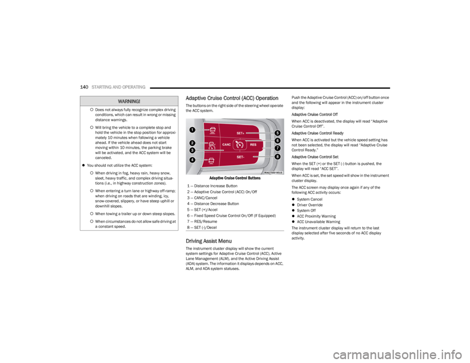
The buttons on the right side of the steering wheel operate
the ACC system.
Adaptive Cruise Control Buttons
Driving Assist Menu
The instrument cluster display will show the current
system settings for Adaptive Cruise Control (ACC), Active
Lane Management (ALM), and the Active Driving Assist
(ADA) system. The information it displays depends on ACC,
ALM, and ADA system statuses. Push the Adaptive Cruise Control (ACC) on/off button once
and the following will appear in the instrument cluster
display:
Adaptive Cruise Control Off
When ACC is deactivated, the display will read “Adaptive
Cruise Control Off”.
Adaptive Cruise Control Ready
When ACC is activated but the vehicle speed setting has
not been selected, the display will read “Adaptive Cruise
Control Ready.”
Adaptive Cruise Control Set
When the SET (+) or the SET (-) button is pushed, the
display will read “ACC SET”.
When ACC is set, the set speed will show in the instrument
cluster display.
The ACC screen may display once again if any of the
following ACC activity occurs:
System Cancel
Driver Override
System Off
ACC Proximity Warning
ACC Unavailable Warning
The instrument cluster display will return to the last
display selected after five seconds of no ACC display
activity.
Does not always fully recognize complex driving
conditions, which can result in wrong or missing
distance warnings.
Will bring the vehicle to a complete stop and
hold the vehicle in the stop position for approxi -
mately 10 minutes when following a vehicle
ahead. If the vehicle ahead does not start
moving within 10 minutes, the parking brake
will be activated, and the ACC system will be
canceled.
You should not utilize the ACC system:
When driving in fog, heavy rain, heavy snow,
sleet, heavy traffic, and complex driving situa-
tions (i.e., in highway construction zones).
When entering a turn lane or highway off-ramp;
when driving on roads that are winding, icy,
snow-covered, slippery, or have steep uphill or
downhill slopes.
When towing a trailer up or down steep slopes.
When circumstances do not allow safe driving at
a constant speed.
WARNING!
1 — Distance Increase Button
2 — Adaptive Cruise Control (ACC) On/Off
3 — CANC/Cancel
4 — Distance Decrease Button
5 — SET (+)/Accel
6 — Fixed Speed Cruise Control On/Off (If Equipped)
7 — RES/Resume
8 — SET (-)/Decel
23_WS_OM_EN_USC_t.book Page 140
Page 145 of 396
STARTING AND OPERATING143
Setting The Following Distance In ACC
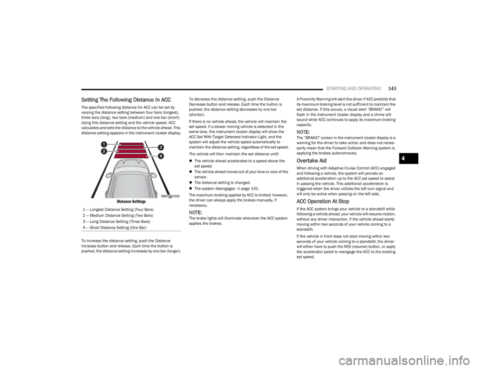
The specified following distance for ACC can be set by
varying the distance setting between four bars (longest),
three bars (long), two bars (medium) and one bar (short).
Using this distance setting and the vehicle speed, ACC
calculates and sets the distance to the vehicle ahead. This
distance setting appears in the instrument cluster display.
Distance Settings
To increase the distance setting, push the Distance
Increase button and release. Each time the button is
pushed, the distance setting increases by one bar (longer). To decrease the distance setting, push the Distance
Decrease button and release. Each time the button is
pushed, the distance setting decreases by one bar
(shorter).
If there is no vehicle ahead, the vehicle will maintain the
set speed. If a slower moving vehicle is detected in the
same lane, the instrument cluster display will show the
ACC Set With Target Detected Indicator Light, and the
system will adjust the vehicle speed automatically to
maintain the distance setting, regardless of the set speed.
The vehicle will then maintain the set distance until:
The vehicle ahead accelerates to a speed above the
set speed.
The vehicle ahead moves out of your lane or view of the
sensor.
The distance setting is changed.
The system disengages
Úpage 141.
The maximum braking applied by ACC is limited; however,
the driver can always apply the brakes manually, if
necessary.
NOTE:The brake lights will illuminate whenever the ACC system
applies the brakes. A Proximity Warning will alert the driver if ACC predicts that
its maximum braking level is not sufficient to maintain the
set distance. If this occurs, a visual alert “BRAKE!” will
flash in the instrument cluster display and a chime will
sound while ACC continues to apply its maximum braking
capacity.
NOTE:The “BRAKE!” screen in the instrument cluster display is a
warning for the driver to take action and does not neces
-
sarily mean that the Forward Collision Warning system is
applying the brakes autonomously.
Overtake Aid
When driving with Adaptive Cruise Control (ACC) engaged
and following a vehicle, the system will provide an
additional acceleration up to the ACC set speed to assist
in passing the vehicle. This additional acceleration is
triggered when the driver utilizes the left turn signal and
will only be active when passing on the left side.
ACC Operation At Stop
If the ACC system brings your vehicle to a standstill while
following a vehicle ahead, your vehicle will resume motion,
without any driver interaction, if the vehicle ahead starts
moving within two seconds of your vehicle coming to a
standstill.
If the vehicle in front does not start moving within two
seconds of your vehicle coming to a standstill, the driver
will either have to push the RES (resume) button, or apply
the accelerator pedal to reengage the ACC to the existing
set speed.
1 — Longest Distance Setting (Four Bars)
2 — Medium Distance Setting (Two Bars)
3 — Long Distance Setting (Three Bars)
4 — Short Distance Setting (One Bar)
4
23_WS_OM_EN_USC_t.book Page 143
Page 149 of 396
STARTING AND OPERATING147
NOTE:
The TSA system will automatically display the
detected road sign using the unit of measurement
(mph or km/h) selected within Uconnect Settings, or
within the instrument cluster display.
If no speed limit signs are detected, the system will
revert to the speed limit signs that are stored in the
Navigation system.
The system always checks the traffic signs indicating
the current speed limit. The system is able to recognize
and display up to two different road signs in the instru -
ment cluster display. These road signs can be found on
the Driver Assist page.
ACTIVATION/DEACTIVATION
The TSA System can be enabled/disabled within the
Uconnect system through the Safety/Driver Assistance
menu. System ON is signaled by road signs shown on the
instrument cluster display.
NOTE:Even if the system is OFF, the speed limit sign will be
displayed when the driver selects it in the HOME screen.
TRAFFIC SIGN ASSIST MODES
TSA has three selectable modes of operation that are
available through the Uconnect system Úpage 197.
Visual
When Visual is selected, the system will alert the driver
when the current speed of the vehicle exceeds the
detected speed limit by showing a graphic in the
instrument cluster display. Visual + Chime
When Visual + Chime is selected, the system will alert the
driver when the current speed of the vehicle exceeds the
detected speed limit by showing a graphic in the
instrument cluster display and by sounding an audible
alert. The audible alert will last for 10 seconds, and the
visual alert will remain on as long as the vehicle is
exceeding the speed limit.
TSA Off
When the TSA system is turned off, the system will not
show any traffic signs (unless selected in the HOME
screen, which will show detected speed limit signs), and
no alerts will be issued to the driver.
INDICATIONS ON THE DISPLAY
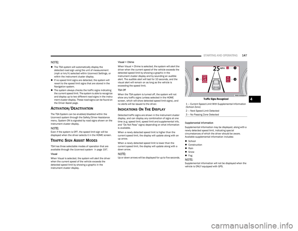
Detected traffic signs are shown in the instrument cluster
display, and can display any combination of signs at one
time (e.g. speed limit, speed limit and supplemental info,
and “Do Not Pass” signs) depending on what information
is available.
When a newly detected speed limit is higher than the
current speed limit, the display will update along with an
up arrow.
When a newly detected speed limit is lower than the
current speed limit, the display will update along with a
down arrow.
NOTE:Up or down arrows will be displayed for up to five seconds.
Traffic Signs Recognized
Supplemental Information
Supplemental information may be displayed, along with a
newly detected speed limit, indicating special
circumstances of which the driver should be aware.
Available supplemental information includes:
School
Construction
Rain
Snow
Fog
NOTE:Supplemental information will not be displayed when the
vehicle is ONLY equipped with GPS.1 — Current Speed Limit With Supplemental Information
(School Zone)
2 — Next Speed Limit Detected
3 — No Passing Zone Detected
4
23_WS_OM_EN_USC_t.book Page 147
Page 160 of 396
158STARTING AND OPERATING
PARKSENSE SYSTEM USAGE
P
RECAUTIONS
NOTE:
Ensure that the front and rear fascias/bumpers are
free of snow, ice, mud, dirt and debris to keep the
ParkSense system operating properly.
Jackhammers, large trucks, and other vibrations could
affect the performance of ParkSense.
When you turn ParkSense off, the instrument cluster
will display “PARKSENSE OFF.” Furthermore, once you
turn ParkSense off, it remains off until you turn it on
again, even if you cycle the ignition.
When you move the gear selector to the REVERSE posi -
tion and ParkSense is turned off, the instrument
cluster will display “PARKSENSE OFF” for as long as the
vehicle is in REVERSE.
ParkSense, when on, will reduce the volume of the
radio when it is sounding a tone.
Clean the ParkSense sensors regularly, taking care not
to scratch or damage them. The sensors must not be
covered with ice, snow, slush, mud, dirt or debris.
Failure to do so can result in the system not working
properly. The ParkSense system might not detect an
obstacle behind or in front of the fascia/bumper, or it
could provide a false indication that an obstacle is
behind or in front of the fascia/bumper.
Use the ParkSense switch to turn the ParkSense
system off if objects such as bicycle carriers, trailer
hitches, etc. are placed within 12 inches (30 cm) of the
rear fascia/bumper. Failure to do so can result in the
system misinterpreting a close object as a sensor
problem, causing the “PARKSENSE UNAVAILABLE
SERVICE REQUIRED” message to be displayed in the
instrument cluster.
ParkSense should be disabled when the liftgate is in
the open position. An opened liftgate could provide a
false indication that an obstacle is behind the vehicle.
SIDE DISTANCE WARNING SYSTEM —
I
F EQUIPPED
The Side Distance Warning system detects the presence
of side obstacles near the vehicle using the parking
sensors located in the front and rear fascia/bumpers.
Side Distance Warning Display
The Side Distance Warning screen will only be displayed if
this feature is enabled within Uconnect Settings
Úpage 197.
The system warns the driver with an acoustic signal and,
when enabled, with visual indications on the instrument
cluster display.
WARNING!
Drivers must be careful when backing up even when
using ParkSense. Always check carefully behind your
vehicle, look behind you, and be sure to check for
pedestrians, animals, other vehicles, obstructions,
and blind spots before backing up. You are respon -
sible for safety and must continue to pay attention to
your surroundings. Failure to do so can result in
serious injury or death.
Before using ParkSense, it is strongly recommended
that the ball mount and hitch ball assembly be
disconnected from the vehicle when the vehicle is
not used for towing. Failure to do so can result in
injury or damage to vehicles or obstacles because
the hitch ball will be much closer to the obstacle than
the rear fascia when the vehicle sounds the contin -
uous tone. Also, the sensors could detect the ball
mount and hitch ball assembly, depending on its size
and shape, giving a false indication that an obstacle
is behind the vehicle.
CAUTION!
ParkSense is only a parking aid and it is unable to
recognize every obstacle, including small obstacles.
Parking curbs might be temporarily detected or not
detected at all. Obstacles located above or below the
sensors will not be detected when they are in close
proximity.
The vehicle must be driven slowly when using Park -
Sense in order to be able to stop in time when an
obstacle is detected. It is recommended that the
driver looks over his/her shoulder when using
ParkSense.
23_WS_OM_EN_USC_t.book Page 158