JEEP WAGONEER 2023 Owners Manual
Manufacturer: JEEP, Model Year: 2023, Model line: WAGONEER, Model: JEEP WAGONEER 2023Pages: 396, PDF Size: 15.17 MB
Page 331 of 396
SERVICING AND MAINTENANCE329
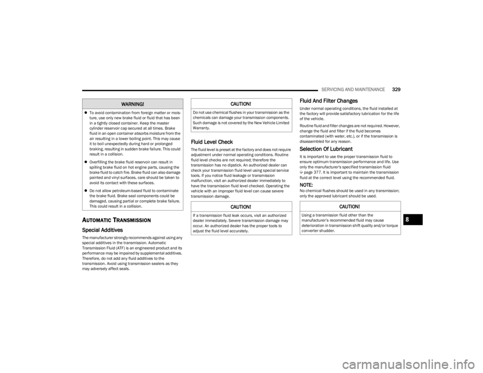
AUTOMATIC TRANSMISSION
Special Additives
The manufacturer strongly recommends against using any
special additives in the transmission. Automatic
Transmission Fluid (ATF) is an engineered product and its
performance may be impaired by supplemental additives.
Therefore, do not add any fluid additives to the
transmission. Avoid using transmission sealers as they
may adversely affect seals.
Fluid Level Check
The fluid level is preset at the factory and does not require
adjustment under normal operating conditions. Routine
fluid level checks are not required; therefore the
transmission has no dipstick. An authorized dealer can
check your transmission fluid level using special service
tools. If you notice fluid leakage or transmission
malfunction, visit an authorized dealer immediately to
have the transmission fluid level checked. Operating the
vehicle with an improper fluid level can cause severe
transmission damage.
Fluid And Filter Changes
Under normal operating conditions, the fluid installed at
the factory will provide satisfactory lubrication for the life
of the vehicle.
Routine fluid and filter changes are not required. However,
change the fluid and filter if the fluid becomes
contaminated (with water, etc.), or if the transmission is
disassembled for any reason.
Selection Of Lubricant
It is important to use the proper transmission fluid to
ensure optimum transmission performance and life. Use
only the manufacturer's specified transmission fluid
Úpage 377. It is important to maintain the transmission
fluid at the correct level using the recommended fluid.
NOTE:No chemical flushes should be used in any transmission;
only the approved lubricant should be used.
To avoid contamination from foreign matter or mois -
ture, use only new brake fluid or fluid that has been
in a tightly closed container. Keep the master
cylinder reservoir cap secured at all times. Brake
fluid in an open container absorbs moisture from the
air resulting in a lower boiling point. This may cause
it to boil unexpectedly during hard or prolonged
braking, resulting in sudden brake failure. This could
result in a collision.
Overfilling the brake fluid reservoir can result in
spilling brake fluid on hot engine parts, causing the
brake fluid to catch fire. Brake fluid can also damage
painted and vinyl surfaces, care should be taken to
avoid its contact with these surfaces.
Do not allow petroleum-based fluid to contaminate
the brake fluid. Brake seal components could be
damaged, causing partial or complete brake failure.
This could result in a collision.
WARNING!CAUTION!
Do not use chemical flushes in your transmission as the
chemicals can damage your transmission components.
Such damage is not covered by the New Vehicle Limited
Warranty.
CAUTION!
If a transmission fluid leak occurs, visit an authorized
dealer immediately. Severe transmission damage may
occur. An authorized dealer has the proper tools to
adjust the fluid level accurately.
CAUTION!
Using a transmission fluid other than the
manufacturer’s recommended fluid may cause
deterioration in transmission shift quality and/or torque
converter shudder.8
23_WS_OM_EN_USC_t.book Page 329
Page 332 of 396
330SERVICING AND MAINTENANCE
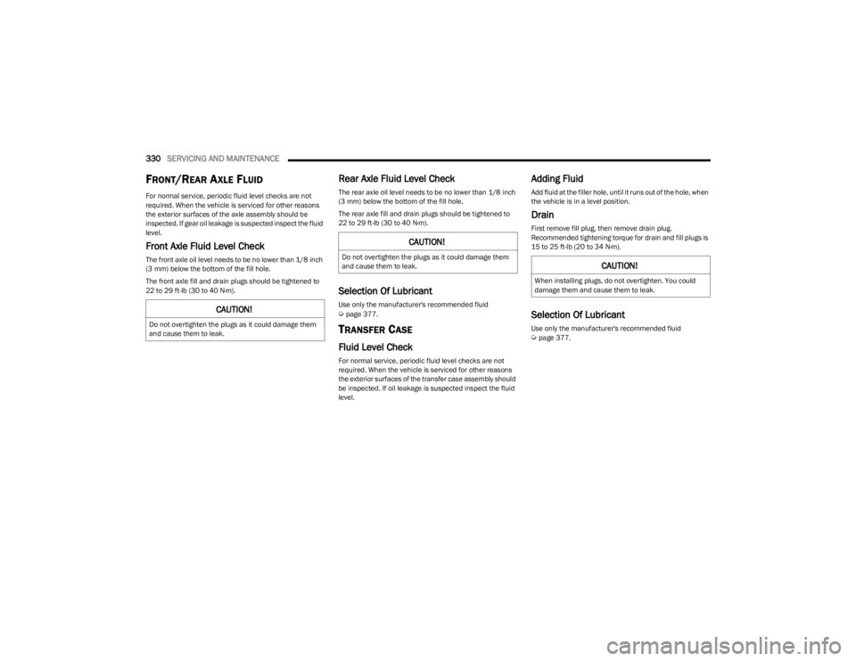
FRONT/REAR AXLE FLUID
For normal service, periodic fluid level checks are not
required. When the vehicle is serviced for other reasons
the exterior surfaces of the axle assembly should be
inspected. If gear oil leakage is suspected inspect the fluid
level.
Front Axle Fluid Level Check
The front axle oil level needs to be no lower than 1/8 inch
(3 mm) below the bottom of the fill hole.
The front axle fill and drain plugs should be tightened to
22 to 29 ft-lb (30 to 40 N·m).
Rear Axle Fluid Level Check
The rear axle oil level needs to be no lower than 1/8 inch
(3 mm) below the bottom of the fill hole.
The rear axle fill and drain plugs should be tightened to
22 to 29 ft-lb (30 to 40 N·m).
Selection Of Lubricant
Use only the manufacturer's recommended fluid Úpage 377.
TRANSFER CASE
Fluid Level Check
For normal service, periodic fluid level checks are not
required. When the vehicle is serviced for other reasons
the exterior surfaces of the transfer case assembly should
be inspected. If oil leakage is suspected inspect the fluid
level.
Adding Fluid
Add fluid at the filler hole, until it runs out of the hole, when
the vehicle is in a level position.
Drain
First remove fill plug, then remove drain plug.
Recommended tightening torque for drain and fill plugs is
15 to 25 ft-lb (20 to 34 N·m).
Selection Of Lubricant
Use only the manufacturer's recommended fluid Úpage 377.
CAUTION!
Do not overtighten the plugs as it could damage them
and cause them to leak.
CAUTION!
Do not overtighten the plugs as it could damage them
and cause them to leak.CAUTION!
When installing plugs, do not overtighten. You could
damage them and cause them to leak.
23_WS_OM_EN_USC_t.book Page 330
Page 333 of 396
SERVICING AND MAINTENANCE331
FUSES
General Information
The fuses protect electrical systems against excessive
current.
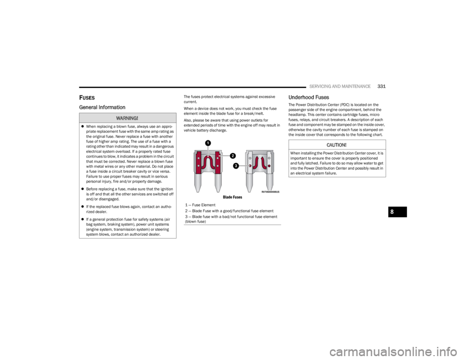
When a device does not work, you must check the fuse
element inside the blade fuse for a break/melt.
Also, please be aware that using power outlets for
extended periods of time with the engine off may result in
vehicle battery discharge.
Blade Fuses
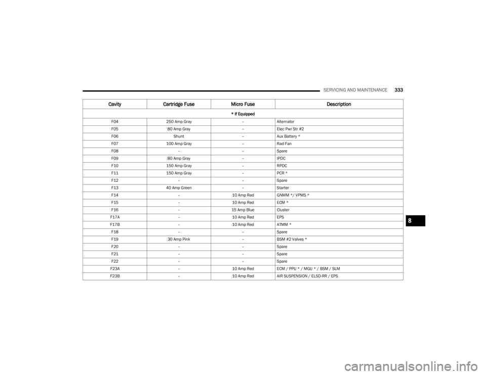
Underhood Fuses
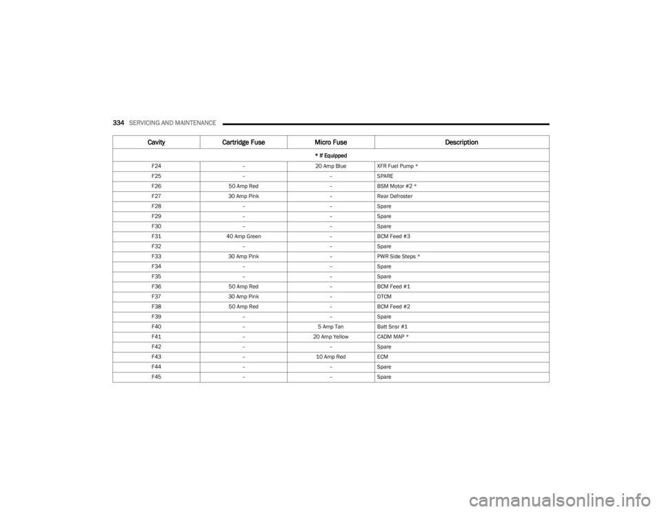
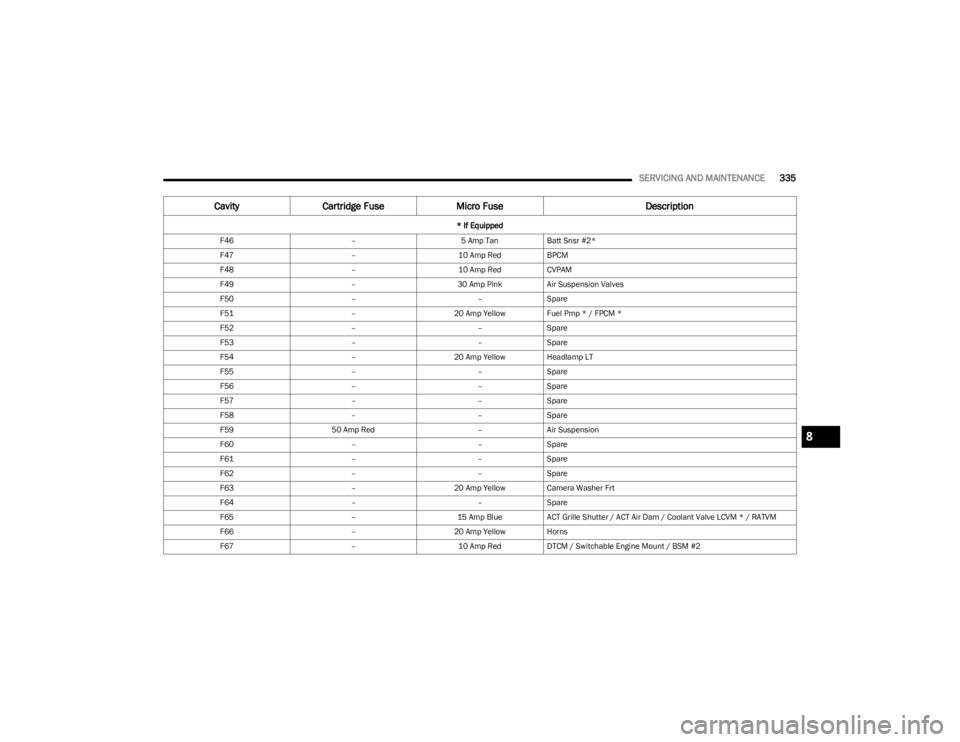
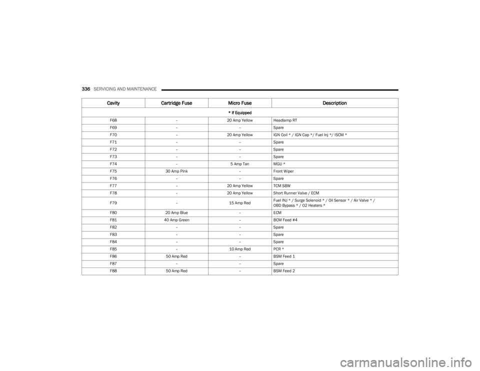
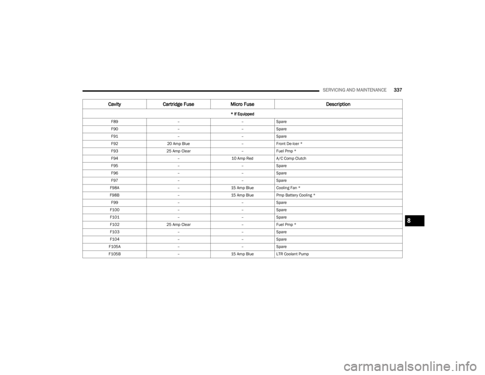
The Power Distribution Center (PDC) is located on the
passenger side of the engine compartment, behind the
headlamp. This center contains cartridge fuses, micro
fuses, relays, and circuit breakers. A description of each
fuse and component may be stamped on the inside cover,
otherwise the cavity number of each fuse is stamped on
the inside cover that corresponds to the following chart.
WARNING!
When replacing a blown fuse, always use an appro -
priate replacement fuse with the same amp rating as
the original fuse. Never replace a fuse with another
fuse of higher amp rating. The use of a fuse with a
rating other than indicated may result in a dangerous
electrical system overload. If a properly rated fuse
continues to blow, it indicates a problem in the circuit
that must be corrected. Never replace a blown fuse
with metal wires or any other material. Do not place
a fuse inside a circuit breaker cavity or vice versa.
Failure to use proper fuses may result in serious
personal injury, fire and/or property damage.
Before replacing a fuse, make sure that the ignition
is off and that all the other services are switched off
and/or disengaged.
If the replaced fuse blows again, contact an autho -
rized dealer.
If a general protection fuse for safety systems (air
bag system, braking system), power unit systems
(engine system, transmission system) or steering
system blows, contact an authorized dealer.
1 — Fuse Element
2 — Blade Fuse with a good/functional fuse element
3 — Blade fuse with a bad/not functional fuse element
(blown fuse)
CAUTION!
When installing the Power Distribution Center cover, it is
important to ensure the cover is properly positioned
and fully latched. Failure to do so may allow water to get
into the Power Distribution Center and possibly result in
an electrical system failure.
8
23_WS_OM_EN_USC_t.book Page 331
Page 334 of 396

332SERVICING AND MAINTENANCE
Power Distribution Center
Cavity Cartridge Fuse Micro Fuse Description
* If Equipped
F01 ––Crank Batt
F02 80 Amp Gray –Elec Pwr Str #1
F03 500 Amp Gray –Starter
23_WS_OM_EN_USC_t.book Page 332
Page 335 of 396
SERVICING AND MAINTENANCE333
F04250 Amp Gray –Alternator
F05 80 Amp Gray –Elec Pwr Str #2
F06 Shunt –Aux Battery *
F07 100 Amp Gray –Rad Fan
F08 ––Spare
F09 80 Amp Gray –IPDC
F10 150 Amp Gray –RPDC
F11 150 Amp Gray –PCR *
F12 ––Spare
F13 40 Amp Green –Starter
F14 –10 Amp RedGNMM */ VPMS *
F15 –10 Amp RedECM *
F16 –15 Amp BlueCluster
F17A –10 Amp RedEPS
F17B –10 Amp RedATMM *
F18 ––Spare
F19 30 Amp Pink –BSM #2 Valves *
F20 ––Spare
F21 ––Spare
F22 ––Spare
F23A –10 Amp RedECM / PPU * / MGU * / BSM / SLM
F23B –10 Amp RedAIR SUSPENSION / ELSD-RR / EPS
Cavity Cartridge Fuse Micro Fuse Description
* If Equipped
8
23_WS_OM_EN_USC_t.book Page 333
Page 336 of 396
334SERVICING AND MAINTENANCE
F24 –20 Amp BlueXFR Fuel Pump *
F25 ––SPARE
F26 50 Amp Red –BSM Motor #2 *
F27 30 Amp Pink –Rear Defroster
F28 ––Spare
F29 ––Spare
F30 ––Spare
F31 40 Amp Green –BCM Feed #3
F32 ––Spare
F33 30 Amp Pink –PWR Side Steps *
F34 ––Spare
F35 ––Spare
F36 50 Amp Red –BCM Feed #1
F37 30 Amp Pink –DTCM
F38 50 Amp Red –BCM Feed #2
F39 ––Spare
F40 –5 Amp TanBatt Snsr #1
F41 –20 Amp Yellow CADM MAP *
F42 ––Spare
F43 –10 Amp RedECM
F44 ––Spare
F45 ––Spare
Cavity Cartridge Fuse Micro Fuse Description
* If Equipped
23_WS_OM_EN_USC_t.book Page 334
Page 337 of 396
SERVICING AND MAINTENANCE335
F46 –5 Amp TanBatt Snsr #2*
F47 –10 Amp RedBPCM
F48 –10 Amp RedCVPAM
F49 –30 Amp PinkAir Suspension Valves
F50 ––Spare
F51 –20 Amp Yellow Fuel Pmp * / FPCM *
F52 ––Spare
F53 ––Spare
F54 –20 Amp Yellow Headlamp LT
F55 ––Spare
F56 ––Spare
F57 ––Spare
F58 ––Spare
F59 50 Amp Red –Air Suspension
F60 ––Spare
F61 ––Spare
F62 ––Spare
F63 –20 Amp Yellow Camera Washer Frt
F64 ––Spare
F65 –15 Amp BlueACT Grille Shutter / ACT Air Dam / Coolant Valve LCVM * / RATVM
F66 –20 Amp Yellow Horns
F67 –10 Amp RedDTCM / Switchable Engine Mount / BSM #2
Cavity Cartridge Fuse Micro Fuse Description
* If Equipped
8
23_WS_OM_EN_USC_t.book Page 335
Page 338 of 396
336SERVICING AND MAINTENANCE
F68 –20 Amp Yellow Headlamp RT
F69 ––Spare
F70 –20 Amp Yellow IGN Coil * / IGN Cap */ Fuel Inj */ ISCM *
F71 ––Spare
F72 ––Spare
F73 ––Spare
F74 –5 Amp TanMGU *
F75 30 Amp Pink –Front Wiper
F76 ––Spare
F77 –20 Amp Yellow TCM SBW
F78 –20 Amp Yellow Short Runner Valve / ECM
F79 –15 Amp RedFuel INJ * / Surge Solenoid * / Oil Sensor * / Air Valve * /
OBD Bypass * / O2 Heaters *
F80 20 Amp Blue –ECM
F81 40 Amp Green –BCM Feed #4
F82 ––Spare
F83 ––Spare
F84 ––Spare
F85 –10 Amp RedPCR *
F86 50 Amp Red –BSM Feed 1
F87 ––Spare
F88 50 Amp Red –BSM Feed 2
Cavity Cartridge Fuse Micro Fuse Description
* If Equipped
23_WS_OM_EN_USC_t.book Page 336
Page 339 of 396
SERVICING AND MAINTENANCE337
F89 ––Spare
F90 ––Spare
F91 ––Spare
F92 20 Amp Blue –Front De-Icer *
F93 25 Amp Clear –Fuel Pmp *
F94 –10 Amp RedA/C Comp Clutch
F95 ––Spare
F96 ––Spare
F97 ––Spare
F98A –15 Amp BlueCooling Fan *
F98B –15 Amp BluePmp Battery Cooling *
F99 ––Spare
F100 ––Spare
F101 ––Spare
F102 25 Amp Clear –Fuel Pmp *
F103 ––Spare
F104 ––Spare
F105A ––Spare
F105B –15 Amp BlueLTR Coolant Pump
CavityCartridge Fuse Micro Fuse Description
* If Equipped
8
23_WS_OM_EN_USC_t.book Page 337
Page 340 of 396
338SERVICING AND MAINTENANCE
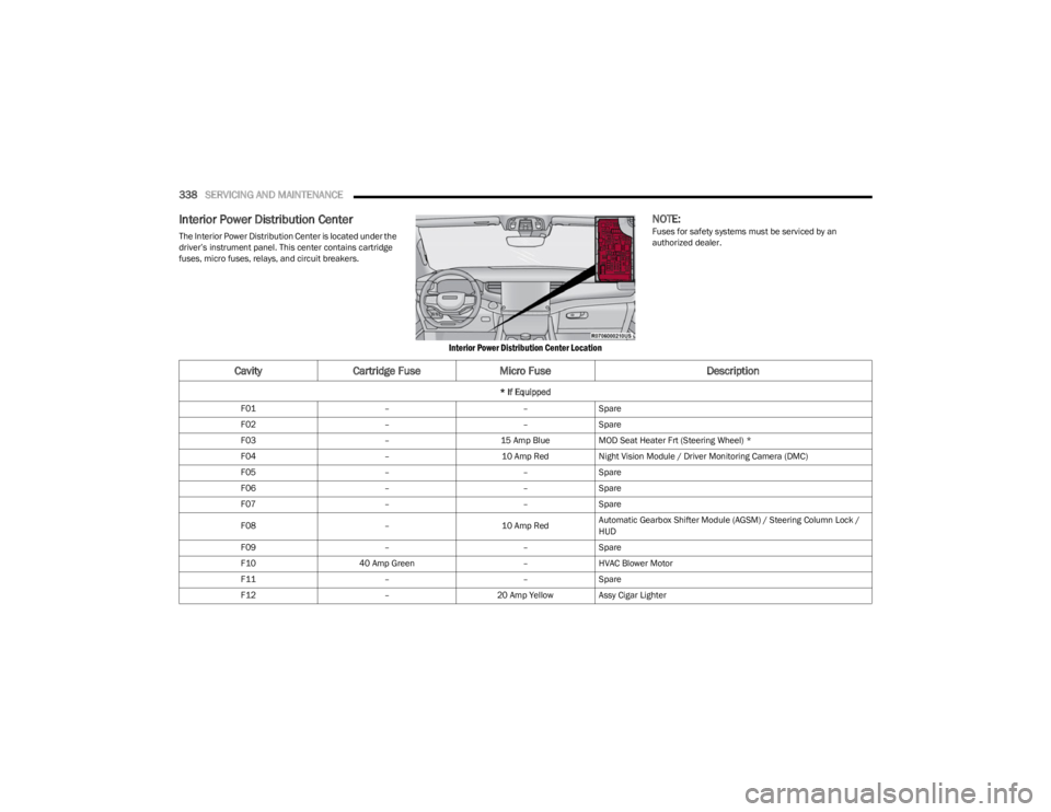
Interior Power Distribution Center
The Interior Power Distribution Center is located under the
driver’s instrument panel. This center contains cartridge
fuses, micro fuses, relays, and circuit breakers.
Interior Power Distribution Center Location
NOTE:Fuses for safety systems must be serviced by an
authorized dealer.
CavityCartridge Fuse Micro Fuse Description
* If Equipped
F01 ––Spare
F02 ––Spare
F03 –15 Amp BlueMOD Seat Heater Frt (Steering Wheel) *
F04 –10 Amp RedNight Vision Module / Driver Monitoring Camera (DMC)
F05 ––Spare
F06 ––Spare
F07 ––Spare
F08 –10 Amp RedAutomatic Gearbox Shifter Module (AGSM) / Steering Column Lock /
HUD
F09 ––Spare
F10 40 Amp Green –HVAC Blower Motor
F11 ––Spare
F12 –20 Amp Yellow Assy Cigar Lighter
23_WS_OM_EN_USC_t.book Page 338