JEEP WRANGLER 2020 Owner handbook (in English)
Manufacturer: JEEP, Model Year: 2020, Model line: WRANGLER, Model: JEEP WRANGLER 2020Pages: 276, PDF Size: 4.47 MB
Page 51 of 276
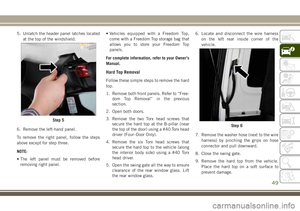
5. Unlatch the header panel latches located
at the top of the windshield.
6. Remove the left-hand panel.
To remove the right panel, follow the steps
above except for step three.
NOTE:
• The left panel must be removed before
removing right panel.• Vehicles equipped with a Freedom Top,
come with a Freedom Top storage bag that
allows you to store your Freedom Top
panels.
For complete information, refer to your Owner's
Manual.
Hard Top Removal
Follow these simple steps to remove the hard
top.
1. Remove both front panels. Refer to “Free-
dom Top Removal” in the previous
section.
2. Open both doors.
3. Remove the two Torx head screws that
secure the hard top at the B-pillar (near
the top of the door) using a #40 Torx head
driver (Four–Door Only).
4. Remove the six Torx head screws that
secure the hard top to the vehicle (along
the interior body side) using a #40 Torx
head driver.
5. Open the swing gate all the way to ensure
clearance of the rear window glass. Lift
the rear window glass.6. Locate and disconnect the wire harness
on the left rear inside corner of the
vehicle.
7. Remove the washer hose (next to the wire
harness) by pinching the grips on hose
connector and pull downward.
8. Close the swing gate.
9. Remove the hard top from the vehicle.
Place the hard top on a soft surface to
prevent damage.
Step 5
Step 6
49
Page 52 of 276
CAUTION!
• The front panel(s) must be positioned
properly to ensure sealing. Improper in-
stallation can cause water to leak into
the vehicle's interior.
• The hard top assembly must be posi-
tioned properly to ensure sealing. Im-
proper installation can cause water to
leak into the vehicle's interior.
• The hard top is not designed to carry any
additional loads such as roof racks,
spare tires, building, hunting, or camp-
ing supplies, and/or luggage, etc. Also, it
was not designed as a structural mem-
ber of the vehicle, and thus cannot prop-
erly carry any additional loads other than
environmental (rain, snow, etc.).
• Do not move your vehicle until the top
has been either fully attached to the
windshield frame and bodyside, or fully
removed.
• The removal of the hard top requires four
adults located on each corner. Failure to
follow this caution could damage the
hard top.
Dual Top — If Equipped
If your vehicle is equipped with a Dual Top,
you must remove one of the tops from the
vehicle.
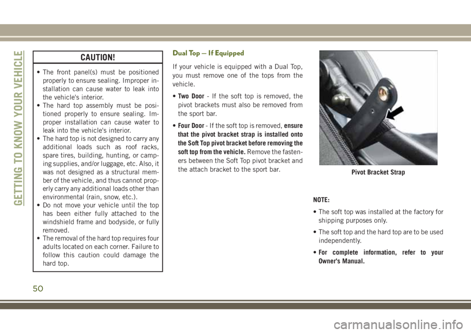
•Two Door- If the soft top is removed, the
pivot brackets must also be removed from
the sport bar.
•Four Door- If the soft top is removed,ensure
that the pivot bracket strap is installed onto
the Soft Top pivot bracket before removing the
soft top from the vehicle.Remove the fasten-
ers between the Soft Top pivot bracket and
the attach bracket to the sport bar.
NOTE:
• The soft top was installed at the factory for
shipping purposes only.
• The soft top and the hard top are to be used
independently.
•For complete information, refer to your
Owner's Manual.
Pivot Bracket Strap
GETTING TO KNOW YOUR VEHICLE
50
Page 53 of 276
Wind Buffeting
Wind buffeting can be described as a
helicopter-type percussion sound. If buffet-
ing occurs with the rear windows open, adjust
the front and rear windows together.
HOOD
Opening The Hood
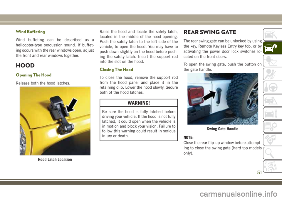
Release both the hood latches.Raise the hood and locate the safety latch,
located in the middle of the hood opening.
Push the safety latch to the left side of the
vehicle, to open the hood. You may have to
push down slightly on the hood before push-
ing the safety latch. Insert the support rod
into the slot on the hood.
Closing The Hood
To close the hood, remove the support rod
from the hood panel and place it in the
retaining clip. Lower the hood slowly. Secure
both of the hood latches.
WARNING!
Be sure the hood is fully latched before
driving your vehicle. If the hood is not fully
latched, it could open when the vehicle is
in motion and block your vision. Failure to
follow this warning could result in serious
injury or death.
REAR SWING GATE
The rear swing gate can be unlocked by using
the key, Remote Keyless Entry key fob, or by
activating the power door lock switches lo-
cated on the front doors.
To open the swing gate, push the button on
the gate handle.
NOTE:
Close the rear flip-up window before attempt-
ing to close the swing gate (hard top models
only).
Hood Latch Location
Swing Gate Handle
51
Page 54 of 276
WARNING!
Driving with the flip-up window open can
allow poisonous exhaust gases into your
vehicle. You and your passengers could be
injured by these fumes. Keep the flip-up
window closed when you are operating the
vehicle.
CAUTION!
Do not push on rear wiper blade when
closing the rear flip-up window, as damage
to the blade will result.
INTERNAL EQUIPMENT
Power Outlets
There are three possible 12 Volt Power Out-
lets in this vehicle.
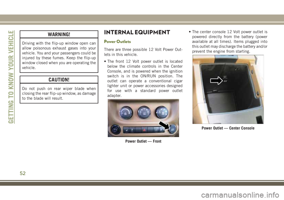
• The front 12 Volt power outlet is located
below the climate controls in the Center
Console, and is powered when the ignition
switch is in the ON/RUN position. The
outlet can operate a conventional cigar
lighter unit or power accessories designed
for use with a standard power outlet
adapter.• The center console 12 Volt power outlet is
powered directly from the battery (power
available at all times). Items plugged into
this outlet may discharge the battery and/or
prevent the engine from starting.
Power Outlet — Front
Power Outlet — Center Console
GETTING TO KNOW YOUR VEHICLE
52
Page 55 of 276
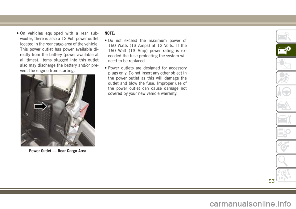
• On vehicles equipped with a rear sub-
woofer, there is also a 12 Volt power outlet
located in the rear cargo area of the vehicle.
This power outlet has power available di-
rectly from the battery (power available at
all times). Items plugged into this outlet
also may discharge the battery and/or pre-
vent the engine from starting.NOTE:
• Do not exceed the maximum power of
160 Watts (13 Amps) at 12 Volts. If the
160 Watt (13 Amp) power rating is ex-
ceeded the fuse protecting the system will
need to be replaced.
• Power outlets are designed for accessory
plugs only. Do not insert any other object in
the power outlet as this will damage the
outlet and blow the fuse. Improper use of
the power outlet can cause damage not
covered by your new vehicle warranty.
Power Outlet — Rear Cargo Area
53
Page 56 of 276
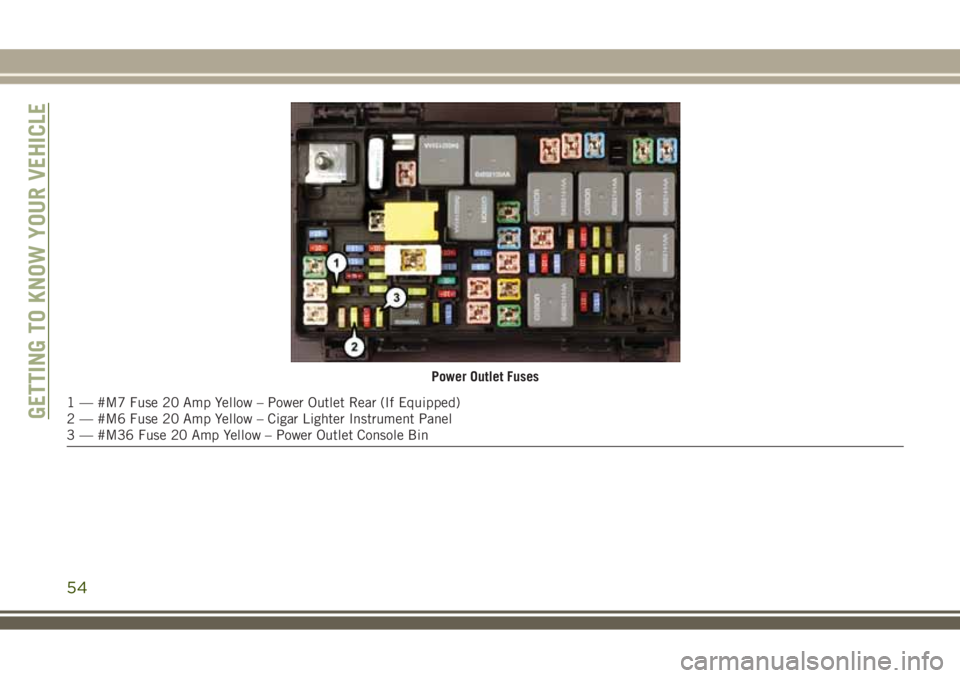
Power Outlet Fuses
1 — #M7 Fuse 20 Amp Yellow – Power Outlet Rear (If Equipped)
2 — #M6 Fuse 20 Amp Yellow – Cigar Lighter Instrument Panel
3 — #M36 Fuse 20 Amp Yellow – Power Outlet Console BinGETTING TO KNOW YOUR VEHICLE
54
Page 57 of 276
GETTING TO KNOW YOUR INSTRUMENT PANEL
INSTRUMENT CLUSTER DISPLAY —
IF EQUIPPED................56
Instrument Cluster Display Location And
Controls.....................56
Instrument Cluster Display Messages . . .57
Gear Shift Indicator (GSI) — If
Equipped....................58
Oil Change Required.............58
WARNING LIGHTS AND MES-
SAGES ....................58
Red Warning Lights..............58
Yellow Warning Lights............61
Yellow Indicator Lights............63
Green Indicator Lights............64
White Indicator Lights............64
Blue Indicator Lights.............64
ONBOARD DIAGNOSTIC SYSTEM —
OBDII ....................64
Onboard Diagnostic System (OBD II)
Cybersecurity.................65
Loose Fuel Filler Cap Message.......65
GETTING TO KNOW YOUR INSTRUMENT PANEL
55
Page 58 of 276
INSTRUMENT CLUSTER
DISPLAY — IF EQUIPPED
Your vehicle may be equipped with an instru-
ment cluster display, which offers useful in-
formation to the driver. With the ignition in
the STOP/OFF mode, opening/closing of a
door will activate the display for viewing, and
display the total miles, or kilometers, in the
odometer. Your instrument cluster display is
designed to display important information
about your vehicle’s systems and features.
Using a driver interactive display located on
the instrument panel, your instrument clus-
ter display can show you how systems are
working and give you warnings when they
aren’t. The steering wheel mounted controls
allow you to scroll through and enter the main
menus and submenus. You can access the
specific information you want and make se-
lections and adjustments.
Instrument Cluster Display Location And
Controls
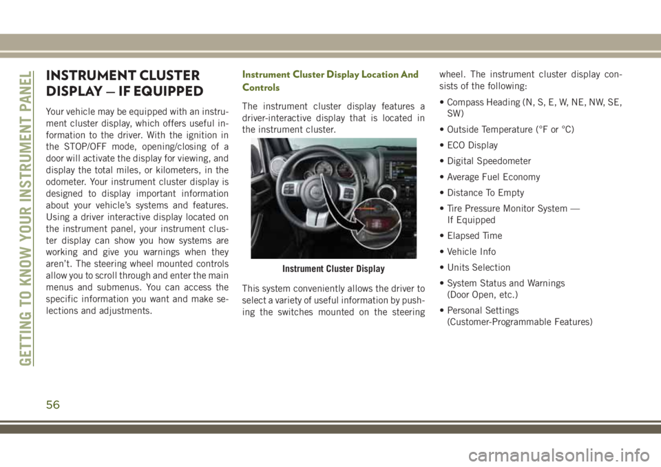
The instrument cluster display features a
driver-interactive display that is located in
the instrument cluster.
This system conveniently allows the driver to
select a variety of useful information by push-
ing the switches mounted on the steeringwheel. The instrument cluster display con-
sists of the following:
• Compass Heading (N, S, E, W, NE, NW, SE,
SW)
• Outside Temperature (°F or °C)
• ECO Display
• Digital Speedometer
• Average Fuel Economy
• Distance To Empty
• Tire Pressure Monitor System —
If Equipped
• Elapsed Time
• Vehicle Info
• Units Selection
• System Status and Warnings
(Door Open, etc.)
• Personal Settings
(Customer-Programmable Features)
Instrument Cluster Display
GETTING TO KNOW YOUR INSTRUMENT PANEL
56
Page 59 of 276
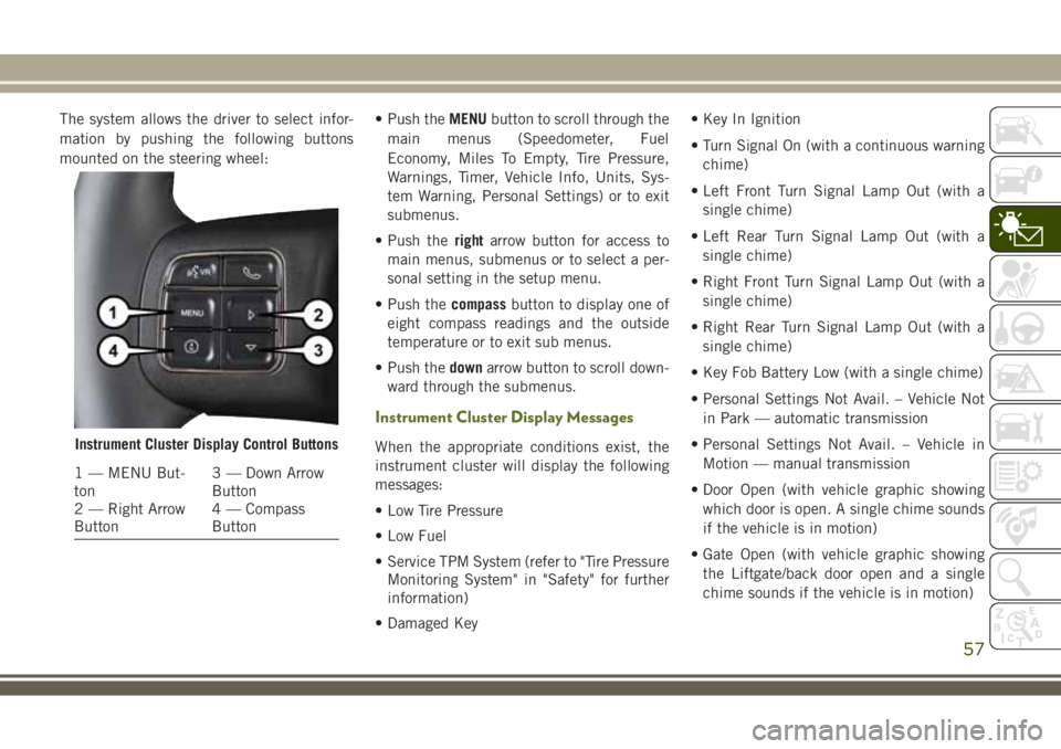
The system allows the driver to select infor-
mation by pushing the following buttons
mounted on the steering wheel:• Push theMENUbutton to scroll through the
main menus (Speedometer, Fuel
Economy, Miles To Empty, Tire Pressure,
Warnings, Timer, Vehicle Info, Units, Sys-
tem Warning, Personal Settings) or to exit
submenus.
• Push therightarrow button for access to
main menus, submenus or to select a per-
sonal setting in the setup menu.
• Push thecompassbutton to display one of
eight compass readings and the outside
temperature or to exit sub menus.
• Push thedownarrow button to scroll down-
ward through the submenus.
Instrument Cluster Display Messages
When the appropriate conditions exist, the
instrument cluster will display the following
messages:
• Low Tire Pressure
• Low Fuel
• Service TPM System (refer to "Tire Pressure
Monitoring System" in "Safety" for further
information)
• Damaged Key• Key In Ignition
• Turn Signal On (with a continuous warning
chime)
• Left Front Turn Signal Lamp Out (with a
single chime)
• Left Rear Turn Signal Lamp Out (with a
single chime)
• Right Front Turn Signal Lamp Out (with a
single chime)
• Right Rear Turn Signal Lamp Out (with a
single chime)
• Key Fob Battery Low (with a single chime)
• Personal Settings Not Avail. – Vehicle Not
in Park — automatic transmission
• Personal Settings Not Avail. – Vehicle in
Motion — manual transmission
• Door Open (with vehicle graphic showing
which door is open. A single chime sounds
if the vehicle is in motion)
• Gate Open (with vehicle graphic showing
the Liftgate/back door open and a single
chime sounds if the vehicle is in motion)Instrument Cluster Display Control Buttons
1 — MENU But-
ton3 — Down Arrow
Button
2 — Right Arrow
Button4 — Compass
Button
57
Page 60 of 276
• Check Gascap (refer to “Refueling The Ve-
hicle” in “Starting And Operating” for fur-
ther information)
• Oil Change Required (with a single chime)
• ECO (Fuel Saver Indicator) — if equipped
Gear Shift Indicator (GSI) — If Equipped
The Gear Shift Indicator (GSI) system is en-
abled on vehicles with a manual transmis-
sion, or when a vehicle with an automatic
transmission is in manual shift mode. The
GSI provides the driver with a visual indica-
tion when the recommended gear shift point
has been reached. This indication notifies
the driver that changing gear will allow a
reduction in fuel consumption. When the up
shift indicator is shown on the display, the
GSI is advising the driver to engage a higher
gear. When the down shift indicator is shown
on the display, the GSI is advising the driver
to engage a lower gear.
The GSI indicator remains illuminated until
the driver changes gear, or the driving condi-
tions return to a situation where changing gear
is not required to improve fuel consumption.
Oil Change Required
Your vehicle is equipped with an engine oil
change indicator system. The “Oil Change
Required” message will display in the instru-
ment cluster display for approximately
10 seconds after a single chime has sounded
to indicate the next scheduled oil change
interval. The engine oil change indicator sys-
tem is duty cycle based, which means the
engine oil change interval may fluctuate de-
pendent upon your personal driving style.
Unless reset, this message will continue to
display each time you turn the ignition switch
to the ON position. To turn off the message
temporarily, push and release theMENUbut-
ton. To reset the oil change indicator system
(after performing the scheduled mainte-
nance), perform the following procedure:
WARNING LIGHTS AND
MESSAGES
The warning/indicator lights will illuminate in
the instrument panel together with a dedi-
cated message and/or acoustic signal when
applicable. These indications are indicativeand precautionary and as such must not be
considered as exhaustive and/or alternative
to the information contained in the Owner’s
Manual, which you are advised to read care-
fully in all cases. Always refer to the informa-
tion in this chapter in the event of a failure
indication. All active telltales will display first
if applicable. The system check menu may
appear different based upon equipment op-
tions and current vehicle status. Some tell-
tales are optional and may not appear.
Red Warning Lights
— Air Bag Warning Light
This light indicates a fault with the air bag,
and will turn on for four to eight seconds as a
bulb check when the ignition is placed in the
ON/RUN or ACC/ON/RUN position. This light
will illuminate with a single chime when a
fault with the air bag has been detected, it
will stay on until the fault is cleared. If the
light is either not on during startup, stays on,
or turns on while driving, have the system
inspected at an authorized dealer as soon as
possible.
GETTING TO KNOW YOUR INSTRUMENT PANEL
58