warning JEEP WRANGLER 2021 Owner handbook (in English)
[x] Cancel search | Manufacturer: JEEP, Model Year: 2021, Model line: WRANGLER, Model: JEEP WRANGLER 2021Pages: 276, PDF Size: 4.47 MB
Page 28 of 276
restraint posts into the holes and push down-
ward. Then adjust it to the appropriate
height.
WARNING!
• A loose head restraint thrown forward in
a collision or hard stop could cause
WARNING!
serious injury or death to occupants of
the vehicle. Always securely stow re-
moved head restraints in a location out-
side the occupant compartment.
• ALL the head restraints MUST be rein-
stalled in the vehicle to properly protect
the occupants. Follow the re-installation
instructions above prior to operating the
vehicle or occupying a seat.
NOTE:
Do not reposition the head restraint 180 de-
grees to the incorrect position in an attempt
to gain additional clearance to the back of the
head.
Rear Head Restraints — 2 Door Model
The rear seat head restraints are not adjust-
able. They can be removed to make it easier
to take out the rear seat. To remove the head
restraint, push the button on each of the two
head restraint guides and pull upward on the
head restraint. Replace the head restraint
before driving the vehicle with passengers in
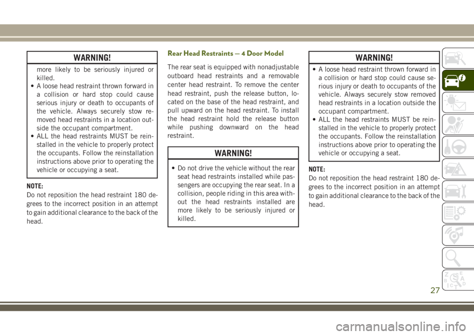
the rear seat. To replace the head restraint,insert the head restraint rods into the guides
and push downward on the head restraint
until locked.WARNING!
• Do not drive the vehicle without the rear
seat head restraints installed while pas-
sengers are occupying the rear seat. In a
collision, people riding in this area with-
out the head restraints installed are
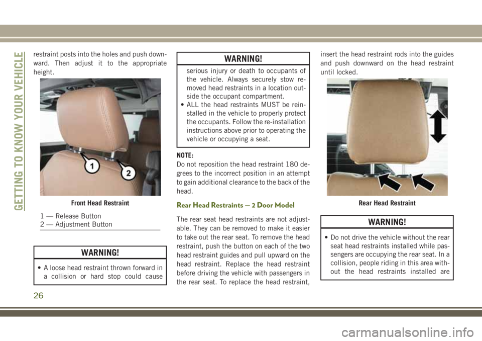
Front Head Restraint
1 — Release Button
2 — Adjustment Button
Rear Head RestraintGETTING TO KNOW YOUR VEHICLE
26
Page 29 of 276
WARNING!
more likely to be seriously injured or
killed.
• A loose head restraint thrown forward in
a collision or hard stop could cause
serious injury or death to occupants of
the vehicle. Always securely stow re-
moved head restraints in a location out-
side the occupant compartment.
• ALL the head restraints MUST be rein-
stalled in the vehicle to properly protect
the occupants. Follow the reinstallation
instructions above prior to operating the
vehicle or occupying a seat.
NOTE:
Do not reposition the head restraint 180 de-
grees to the incorrect position in an attempt
to gain additional clearance to the back of the
head.
Rear Head Restraints—4DoorModel
The rear seat is equipped with nonadjustable
outboard head restraints and a removable
center head restraint. To remove the center
head restraint, push the release button, lo-
cated on the base of the head restraint, and
pull upward on the head restraint. To install
the head restraint hold the release button
while pushing downward on the head
restraint.
WARNING!
• Do not drive the vehicle without the rear
seat head restraints installed while pas-
sengers are occupying the rear seat. In a
collision, people riding in this area with-
out the head restraints installed are
more likely to be seriously injured or
killed.
WARNING!
• A loose head restraint thrown forward in
a collision or hard stop could cause se-
rious injury or death to occupants of the
vehicle. Always securely stow removed
head restraints in a location outside the
occupant compartment.
• ALL the head restraints MUST be rein-
stalled in the vehicle to properly protect
the occupants. Follow the reinstallation
instructions above prior to operating the
vehicle or occupying a seat.
NOTE:
Do not reposition the head restraint 180 de-
grees to the incorrect position in an attempt
to gain additional clearance to the back of the
head.
27
Page 30 of 276
STEERING WHEEL
Tilt Steering Column
This feature allows you to tilt the steering
column upward or downward. The tilt lever is
located on the steering column, below the
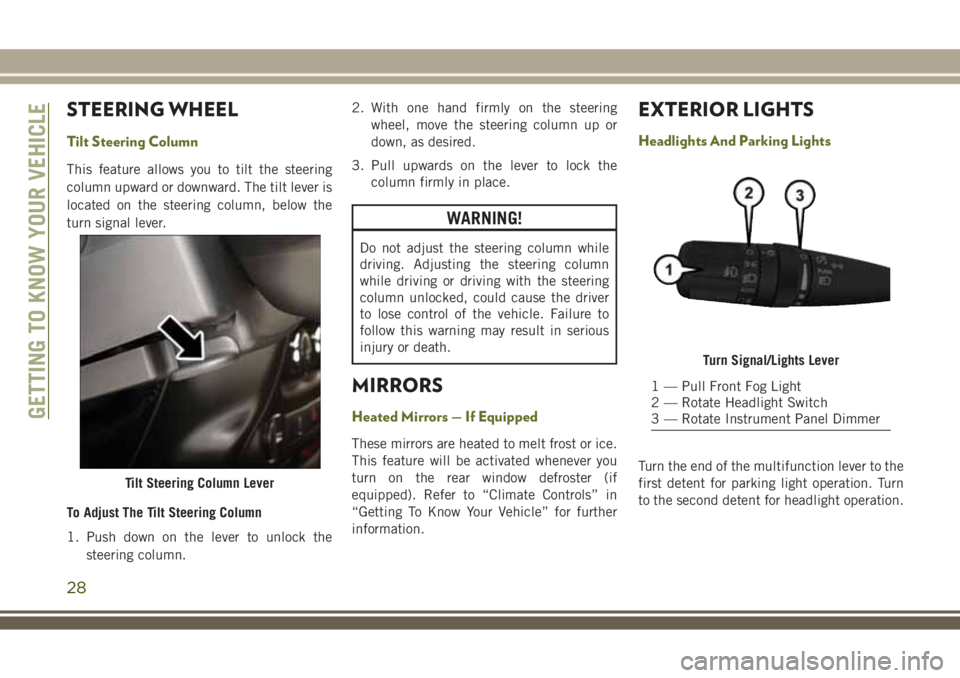
turn signal lever.
To Adjust The Tilt Steering Column
1. Push down on the lever to unlock the
steering column.2. With one hand firmly on the steering
wheel, move the steering column up or
down, as desired.
3. Pull upwards on the lever to lock the
column firmly in place.
WARNING!
Do not adjust the steering column while
driving. Adjusting the steering column
while driving or driving with the steering
column unlocked, could cause the driver
to lose control of the vehicle. Failure to
follow this warning may result in serious
injury or death.
MIRRORS
Heated Mirrors — If Equipped
These mirrors are heated to melt frost or ice.
This feature will be activated whenever you
turn on the rear window defroster (if
equipped). Refer to “Climate Controls” in
“Getting To Know Your Vehicle” for further
information.
EXTERIOR LIGHTS
Headlights And Parking Lights
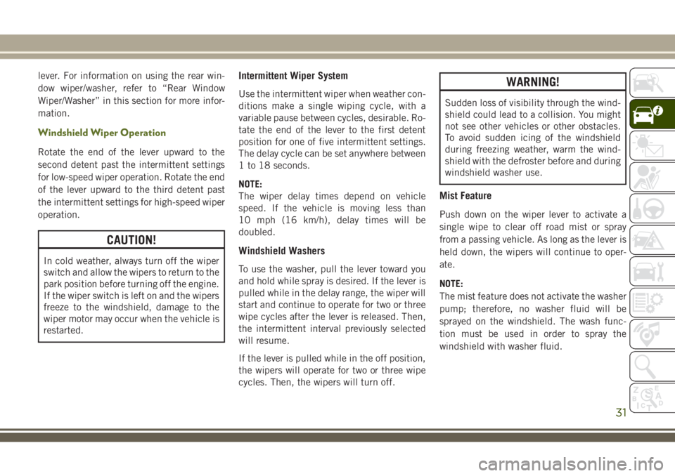
Turn the end of the multifunction lever to the
first detent for parking light operation. Turn
to the second detent for headlight operation.
Tilt Steering Column Lever
Turn Signal/Lights Lever
1 — Pull Front Fog Light
2 — Rotate Headlight Switch
3 — Rotate Instrument Panel Dimmer
GETTING TO KNOW YOUR VEHICLE
28
Page 33 of 276
lever. For information on using the rear win-
dow wiper/washer, refer to “Rear Window
Wiper/Washer” in this section for more infor-
mation.
Windshield Wiper Operation
Rotate the end of the lever upward to the
second detent past the intermittent settings
for low-speed wiper operation. Rotate the end
of the lever upward to the third detent past
the intermittent settings for high-speed wiper
operation.
CAUTION!
In cold weather, always turn off the wiper
switch and allow the wipers to return to the
park position before turning off the engine.
If the wiper switch is left on and the wipers
freeze to the windshield, damage to the
wiper motor may occur when the vehicle is
restarted.
Intermittent Wiper System
Use the intermittent wiper when weather con-
ditions make a single wiping cycle, with a
variable pause between cycles, desirable. Ro-
tate the end of the lever to the first detent
position for one of five intermittent settings.
The delay cycle can be set anywhere between
1 to 18 seconds.
NOTE:
The wiper delay times depend on vehicle
speed. If the vehicle is moving less than
10 mph (16 km/h), delay times will be
doubled.
Windshield Washers
To use the washer, pull the lever toward you
and hold while spray is desired. If the lever is
pulled while in the delay range, the wiper will
start and continue to operate for two or three
wipe cycles after the lever is released. Then,
the intermittent interval previously selected
will resume.
If the lever is pulled while in the off position,
the wipers will operate for two or three wipe
cycles. Then, the wipers will turn off.
WARNING!
Sudden loss of visibility through the wind-
shield could lead to a collision. You might
not see other vehicles or other obstacles.
To avoid sudden icing of the windshield
during freezing weather, warm the wind-
shield with the defroster before and during
windshield washer use.
Mist Feature
Push down on the wiper lever to activate a
single wipe to clear off road mist or spray
from a passing vehicle. As long as the lever is
held down, the wipers will continue to oper-
ate.
NOTE:
The mist feature does not activate the washer
pump; therefore, no washer fluid will be
sprayed on the windshield. The wash func-
tion must be used in order to spray the
windshield with washer fluid.
31
Page 40 of 276
CAUTION!
Failure to follow these cautions can cause
damage to the heating elements:
• Use care when washing the inside of
the rear window. Do not use abrasive
window cleaners on the interior surface
of the window. Use a soft cloth and a
mild washing solution, wiping parallel
to the heating elements. Labels can be
peeled off after soaking with warm
water.
• Do not use scrapers, sharp instru-
ments, or abrasive window cleaners on
the interior surface of the window.
• Keep all objects a safe distance from
the window.
Outside Air Intake
Make sure the air intake, located directly in
front of the windshield, is free of obstruc-
tions, such as leaves. Leaves collected in the
air intake may reduce airflow, and if they
enter the plenum, they could plug the water
drains. In Winter months, make sure the air
intake is clear of ice, slush, and snow.
Cabin Air Filter
The climate control system filters out dust
and pollen from the air. Contact an autho-
rized dealer to service your cabin air filter,
and to have it replaced when needed.
POWER WINDOWS — IF
EQUIPPED
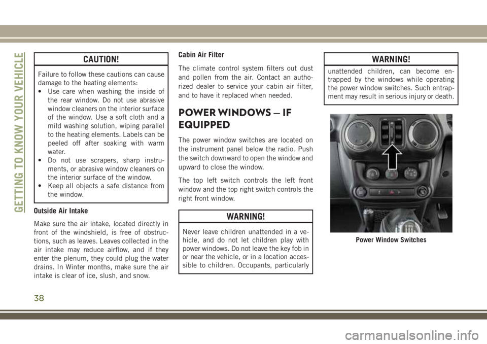
The power window switches are located on
the instrument panel below the radio. Push
the switch downward to open the window and
upward to close the window.
The top left switch controls the left front
window and the top right switch controls the
right front window.
WARNING!
Never leave children unattended in a ve-
hicle, and do not let children play with
power windows. Do not leave the key fob in
or near the vehicle, or in a location acces-
sible to children. Occupants, particularly
WARNING!
unattended children, can become en-
trapped by the windows while operating
the power window switches. Such entrap-
ment may result in serious injury or death.
Power Window Switches
GETTING TO KNOW YOUR VEHICLE
38
Page 49 of 276
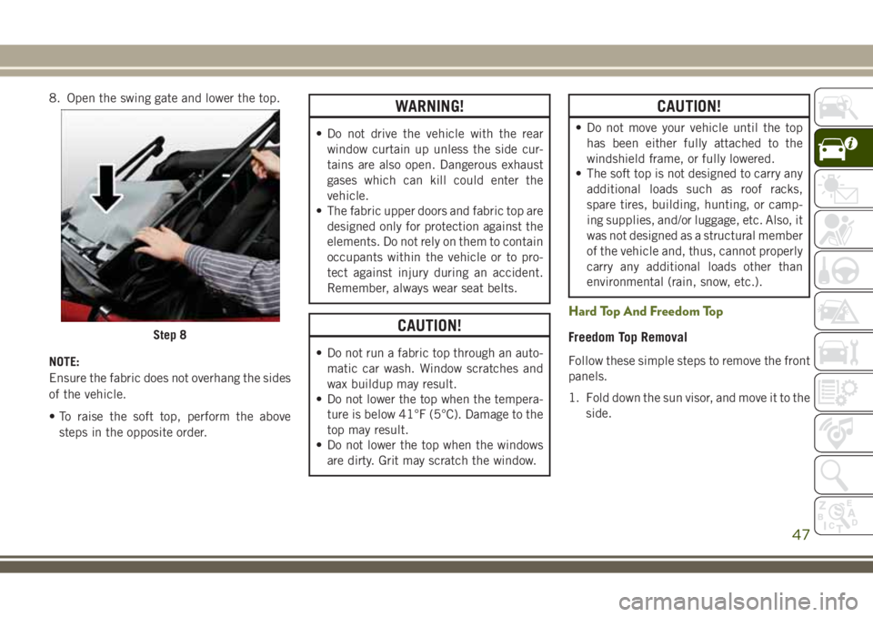
8. Open the swing gate and lower the top.
NOTE:
Ensure the fabric does not overhang the sides
of the vehicle.
• To raise the soft top, perform the above
steps in the opposite order.WARNING!
• Do not drive the vehicle with the rear
window curtain up unless the side cur-
tains are also open. Dangerous exhaust
gases which can kill could enter the
vehicle.
• The fabric upper doors and fabric top are
designed only for protection against the
elements. Do not rely on them to contain
occupants within the vehicle or to pro-
tect against injury during an accident.
Remember, always wear seat belts.
CAUTION!
• Do not run a fabric top through an auto-
matic car wash. Window scratches and
wax buildup may result.
• Do not lower the top when the tempera-
ture is below 41°F (5°C). Damage to the
top may result.
• Do not lower the top when the windows
are dirty. Grit may scratch the window.
CAUTION!
• Do not move your vehicle until the top
has been either fully attached to the
windshield frame, or fully lowered.
• The soft top is not designed to carry any
additional loads such as roof racks,
spare tires, building, hunting, or camp-
ing supplies, and/or luggage, etc. Also, it
was not designed as a structural member
of the vehicle and, thus, cannot properly
carry any additional loads other than
environmental (rain, snow, etc.).
Hard Top And Freedom Top
Freedom Top Removal
Follow these simple steps to remove the front
panels.
1. Fold down the sun visor, and move it to the
side.
Step 8
47
Page 53 of 276
Wind Buffeting
Wind buffeting can be described as a
helicopter-type percussion sound. If buffet-
ing occurs with the rear windows open, adjust
the front and rear windows together.
HOOD
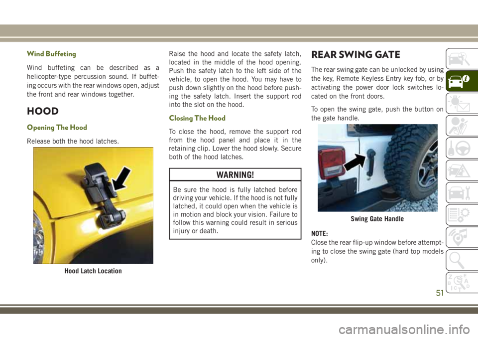
Opening The Hood
Release both the hood latches.Raise the hood and locate the safety latch,
located in the middle of the hood opening.
Push the safety latch to the left side of the
vehicle, to open the hood. You may have to
push down slightly on the hood before push-
ing the safety latch. Insert the support rod
into the slot on the hood.
Closing The Hood
To close the hood, remove the support rod
from the hood panel and place it in the
retaining clip. Lower the hood slowly. Secure
both of the hood latches.
WARNING!
Be sure the hood is fully latched before
driving your vehicle. If the hood is not fully
latched, it could open when the vehicle is
in motion and block your vision. Failure to
follow this warning could result in serious
injury or death.
REAR SWING GATE
The rear swing gate can be unlocked by using
the key, Remote Keyless Entry key fob, or by
activating the power door lock switches lo-
cated on the front doors.
To open the swing gate, push the button on
the gate handle.
NOTE:
Close the rear flip-up window before attempt-
ing to close the swing gate (hard top models
only).
Hood Latch Location
Swing Gate Handle
51
Page 54 of 276
WARNING!
Driving with the flip-up window open can
allow poisonous exhaust gases into your
vehicle. You and your passengers could be
injured by these fumes. Keep the flip-up
window closed when you are operating the
vehicle.
CAUTION!
Do not push on rear wiper blade when
closing the rear flip-up window, as damage
to the blade will result.
INTERNAL EQUIPMENT
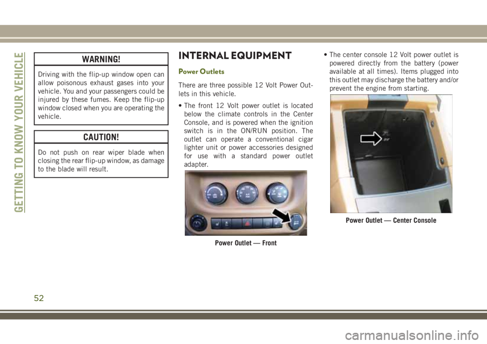
Power Outlets
There are three possible 12 Volt Power Out-
lets in this vehicle.
• The front 12 Volt power outlet is located
below the climate controls in the Center
Console, and is powered when the ignition
switch is in the ON/RUN position. The
outlet can operate a conventional cigar
lighter unit or power accessories designed
for use with a standard power outlet
adapter.• The center console 12 Volt power outlet is
powered directly from the battery (power
available at all times). Items plugged into
this outlet may discharge the battery and/or
prevent the engine from starting.
Power Outlet — Front
Power Outlet — Center Console
GETTING TO KNOW YOUR VEHICLE
52
Page 57 of 276
GETTING TO KNOW YOUR INSTRUMENT PANEL
INSTRUMENT CLUSTER DISPLAY —
IF EQUIPPED................56
Instrument Cluster Display Location And
Controls.....................56
Instrument Cluster Display Messages . . .57
Gear Shift Indicator (GSI) — If
Equipped....................58
Oil Change Required.............58
WARNING LIGHTS AND MES-
SAGES ....................58
Red Warning Lights..............58
Yellow Warning Lights............61
Yellow Indicator Lights............63
Green Indicator Lights............64
White Indicator Lights............64
Blue Indicator Lights.............64
ONBOARD DIAGNOSTIC SYSTEM —
OBDII ....................64
Onboard Diagnostic System (OBD II)
Cybersecurity.................65
Loose Fuel Filler Cap Message.......65
GETTING TO KNOW YOUR INSTRUMENT PANEL
55
Page 58 of 276
INSTRUMENT CLUSTER
DISPLAY — IF EQUIPPED
Your vehicle may be equipped with an instru-
ment cluster display, which offers useful in-
formation to the driver. With the ignition in
the STOP/OFF mode, opening/closing of a
door will activate the display for viewing, and
display the total miles, or kilometers, in the
odometer. Your instrument cluster display is
designed to display important information
about your vehicle’s systems and features.
Using a driver interactive display located on
the instrument panel, your instrument clus-
ter display can show you how systems are
working and give you warnings when they
aren’t. The steering wheel mounted controls
allow you to scroll through and enter the main
menus and submenus. You can access the
specific information you want and make se-
lections and adjustments.
Instrument Cluster Display Location And
Controls
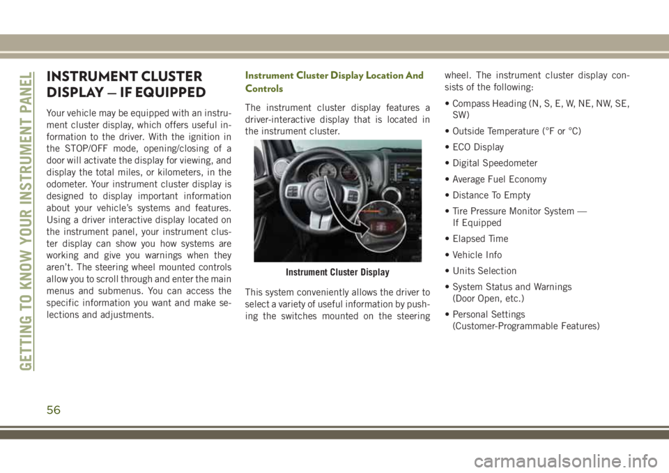
The instrument cluster display features a
driver-interactive display that is located in
the instrument cluster.
This system conveniently allows the driver to
select a variety of useful information by push-
ing the switches mounted on the steeringwheel. The instrument cluster display con-
sists of the following:
• Compass Heading (N, S, E, W, NE, NW, SE,
SW)
• Outside Temperature (°F or °C)
• ECO Display
• Digital Speedometer
• Average Fuel Economy
• Distance To Empty
• Tire Pressure Monitor System —
If Equipped
• Elapsed Time
• Vehicle Info
• Units Selection
• System Status and Warnings
(Door Open, etc.)
• Personal Settings
(Customer-Programmable Features)
Instrument Cluster Display
GETTING TO KNOW YOUR INSTRUMENT PANEL
56