warning JEEP WRANGLER 2021 Owner handbook (in English)
[x] Cancel search | Manufacturer: JEEP, Model Year: 2021, Model line: WRANGLER, Model: JEEP WRANGLER 2021Pages: 276, PDF Size: 4.47 MB
Page 6 of 276
HOW TO USE THIS MANUAL
Essential Information
Consult the Table of Contents to determine
which section contains the information you
desire.
Since the specification of your vehicle de-
pends on the items of equipment ordered,
certain descriptions and illustrations may dif-
fer from your vehicle's equipment.
The detailed index at the back of this Owner's
Manual contains a complete listing of all
subjects.
Symbols
Some vehicle components have colored la-
bels whose symbols indicate precautions to
be observed when using this component.
ROLLOVER WARNING
Utility vehicles have a significantly higher
rollover rate than other types of vehicles. This
vehicle has a higher ground clearance and a
higher center of gravity than many passenger
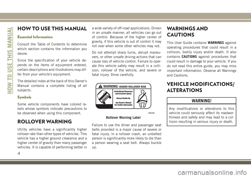
vehicles. It is capable of performing better ina wide variety of off-road applications. Driven
in an unsafe manner, all vehicles can go out
of control. Because of the higher center of
gravity, if this vehicle is out of control it may
roll over when some other vehicles may not.
Do not attempt sharp turns, abrupt maneu-
vers, or other unsafe driving actions that can
cause loss of vehicle control. Failure to oper-
ate this vehicle safely may result in a colli-
sion, rollover of the vehicle, and severe or
fatal injury. Drive carefully.
Failure to use the driver and passenger seat
belts provided is a major cause of severe or
fatal injury. In a rollover crash, an unbelted
person is significantly more likely to die than
a person wearing a seat belt. Always buckle
up.
WARNINGS AND
CAUTIONS
This User Guide containsWARNINGSagainst
operating procedures that could result in a
collision, bodily injury and/or death. It also
containsCAUTIONSagainst procedures that
could result in damage to your vehicle. If you
do not read this entire guide, you may miss
important information. Observe all Warnings
and Cautions.
VEHICLE MODIFICATIONS/
ALTERATIONS
WARNING!
Any modifications or alterations to this
vehicle could seriously affect its roadwor-
thiness and safety and may lead to a col-
lision resulting in serious injury or death.
Rollover Warning Label
HOW TO USE THIS MANUAL
4
Page 16 of 276
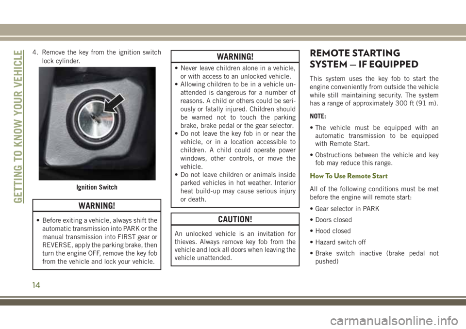
4. Remove the key from the ignition switch
lock cylinder.
WARNING!
• Before exiting a vehicle, always shift the
automatic transmission into PARK or the
manual transmission into FIRST gear or
REVERSE, apply the parking brake, then
turn the engine OFF, remove the key fob
from the vehicle and lock your vehicle.
WARNING!
• Never leave children alone in a vehicle,
or with access to an unlocked vehicle.
• Allowing children to be in a vehicle un-
attended is dangerous for a number of
reasons. A child or others could be seri-
ously or fatally injured. Children should
be warned not to touch the parking
brake, brake pedal or the gear selector.
• Do not leave the key fob in or near the
vehicle, or in a location accessible to
children. A child could operate power
windows, other controls, or move the
vehicle.
• Do not leave children or animals inside
parked vehicles in hot weather. Interior
heat build-up may cause serious injury
or death.
CAUTION!
An unlocked vehicle is an invitation for
thieves. Always remove key fob from the
vehicle and lock all doors when leaving the
vehicle unattended.
REMOTE STARTING
SYSTEM — IF EQUIPPED
This system uses the key fob to start the
engine conveniently from outside the vehicle
while still maintaining security. The system
has a range of approximately 300 ft (91 m).
NOTE:
• The vehicle must be equipped with an
automatic transmission to be equipped
with Remote Start.
• Obstructions between the vehicle and key
fob may reduce this range.
How To Use Remote Start
All of the following conditions must be met
before the engine will remote start:
• Gear selector in PARK
• Doors closed
• Hood closed
• Hazard switch off
• Brake switch inactive (brake pedal not
pushed)Ignition Switch
GETTING TO KNOW YOUR VEHICLE
14
Page 17 of 276
• Ignition key removed from ignition
• Battery at an acceptable charge level
• System not disabled from previous remote
start event
• Vehicle security alarm not active
WARNING!
• Do not start or run an engine in a closed
garage or confined area. Exhaust gas
contains Carbon Monoxide (CO) which is
odorless and colorless. Carbon Monox-
ide is poisonous and can cause serious
injury or death when inhaled.
• Keep key fobs away from children. Op-
eration of the Remote Start System, win-
dows, door locks or other controls could
cause serious injury or death.
Remote Start Abort Message
The following messages will display in the
instrument cluster display if the vehicle fails to
remote start or exits remote start prematurely:
• Remote Start Aborted — Door Open
• Remote Start Aborted — Hood Open
• Remote Start Aborted — Fuel Low
• Remote Start Aborted — Swing Gate Open
• Remote Start Aborted — System Fault
The instrument cluster display message stays
active until the ignition is turned to the ON/
RUN position.
To Enter Remote Start
Push and release the remote start button on
the key fob twice within five seconds. The
vehicle doors will lock, the parking lights will
flash and the horn will chirp twice (if pro-
grammed). Then, the engine will start and the
vehicle will remain in the remote start mode
for a 15-minute cycle.NOTE:
• The park lamps will turn on and remain on
during remote start mode.
• For security, power window operation is
disabled when the vehicle is in the remote
start mode.
• The engine can be started two consecutive
times (two 15-minute cycles) with the key
fob. However, the ignition switch must be
cycled to the ON/RUN position before you
can repeat the start sequence for a third
cycle.
Remote start will also cancel if any of the
following occur:
• The engine stalls or RPM exceeds 2500.
• Any engine warning lamps come on.
• The hood is opened.
• The hazard switch is pushed.
• The transmission is moved out of PARK.
• The brake pedal is pushed.
15
Page 21 of 276
DOORS
CAUTION!
Careless handling and storage of the re-
movable door panels may damage the
seals, causing water to leak into the vehi-
cle’s interior.
Upper Half Door Window Removal — If
Equipped
Grasp the half door window and pull upward.
Upper Half Door Window Installation — If
Equipped
1.Grasp the half door window and line up the
pins with the pockets in the lower door.
2. Push down to ensure the half door window
is fully seated.
Front Door Removal
WARNING!
Do not drive your vehicle on public roads
with the doors removed as you will lose the
WARNING!
protection they can provide. This proce-
dure is furnished for use during off-road
operation only.
NOTE:
Hinge pin can break if overtightened during
door reinstall (Max Torque: 10 N·m / 7.5 ft· lb).
1. Roll down the glass window to prevent any
damage.
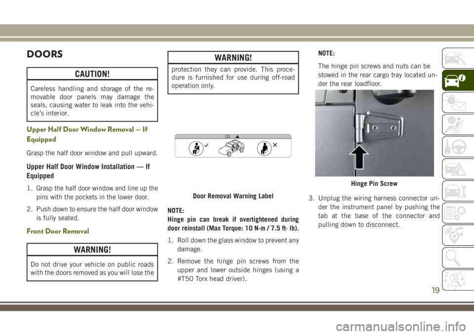
2. Remove the hinge pin screws from the
upper and lower outside hinges (using a
#T50 Torx head driver).NOTE:
The hinge pin screws and nuts can be
stowed in the rear cargo tray located un-
der the rear loadfloor.
3. Unplug the wiring harness connector un-
der the instrument panel by pushing the
tab at the base of the connector and
pulling down to disconnect.
Door Removal Warning Label
Hinge Pin Screw
19
Page 22 of 276
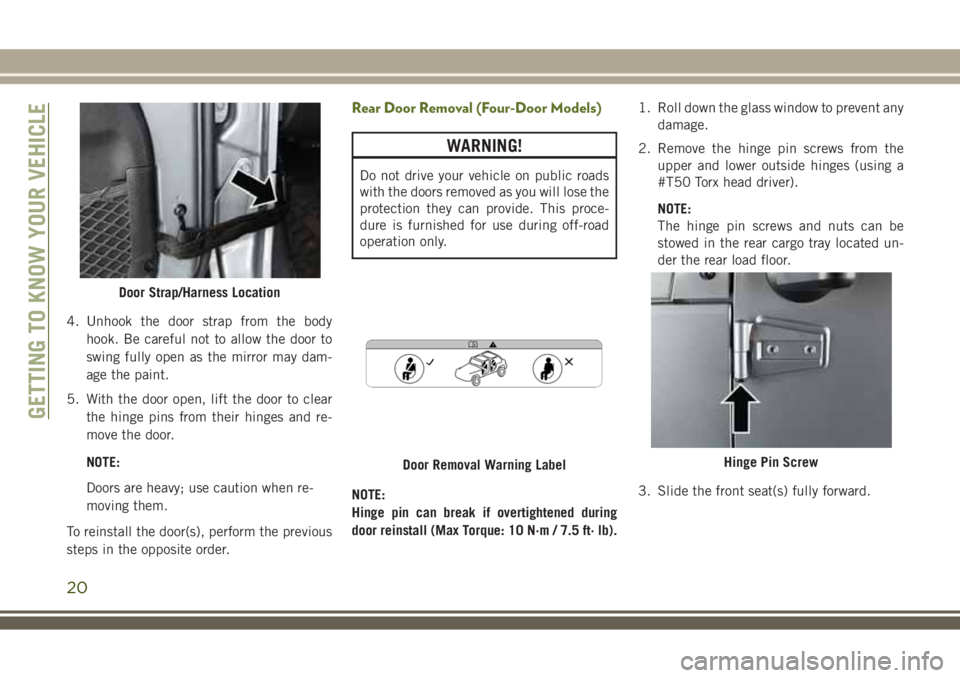
4. Unhook the door strap from the body
hook. Be careful not to allow the door to
swing fully open as the mirror may dam-
age the paint.
5. With the door open, lift the door to clear
the hinge pins from their hinges and re-
move the door.
NOTE:
Doors are heavy; use caution when re-
moving them.
To reinstall the door(s), perform the previous
steps in the opposite order.
Rear Door Removal (Four-Door Models)
WARNING!
Do not drive your vehicle on public roads
with the doors removed as you will lose the
protection they can provide. This proce-
dure is furnished for use during off-road
operation only.
NOTE:
Hinge pin can break if overtightened during
door reinstall (Max Torque: 10 N·m / 7.5 ft· lb).1. Roll down the glass window to prevent any
damage.
2. Remove the hinge pin screws from the
upper and lower outside hinges (using a
#T50 Torx head driver).
NOTE:
The hinge pin screws and nuts can be
stowed in the rear cargo tray located un-
der the rear load floor.
3. Slide the front seat(s) fully forward.
Door Strap/Harness Location
Door Removal Warning LabelHinge Pin Screw
GETTING TO KNOW YOUR VEHICLE
20
Page 23 of 276
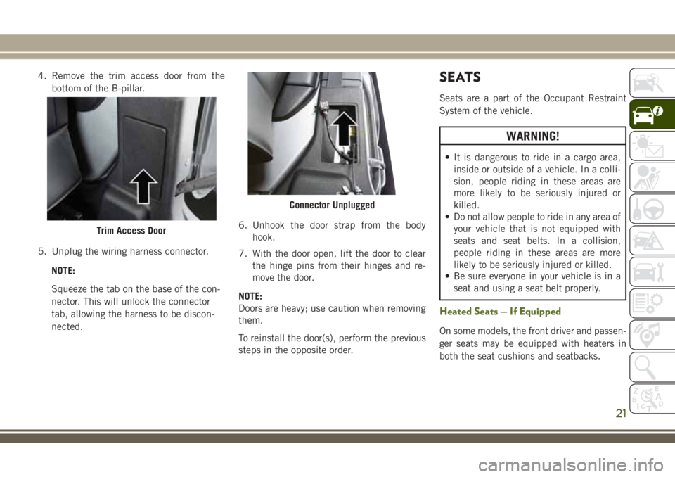
4. Remove the trim access door from the
bottom of the B-pillar.
5. Unplug the wiring harness connector.
NOTE:
Squeeze the tab on the base of the con-
nector. This will unlock the connector
tab, allowing the harness to be discon-
nected.6. Unhook the door strap from the body
hook.
7. With the door open, lift the door to clear
the hinge pins from their hinges and re-
move the door.
NOTE:
Doors are heavy; use caution when removing
them.
To reinstall the door(s), perform the previous
steps in the opposite order.SEATS
Seats are a part of the Occupant Restraint
System of the vehicle.
WARNING!
• It is dangerous to ride in a cargo area,
inside or outside of a vehicle. In a colli-
sion, people riding in these areas are
more likely to be seriously injured or
killed.
• Do not allow people to ride in any area of
your vehicle that is not equipped with
seats and seat belts. In a collision,
people riding in these areas are more
likely to be seriously injured or killed.
• Be sure everyone in your vehicle is in a
seat and using a seat belt properly.
Heated Seats — If Equipped
On some models, the front driver and passen-
ger seats may be equipped with heaters in
both the seat cushions and seatbacks.
Trim Access Door
Connector Unplugged
21
Page 24 of 276
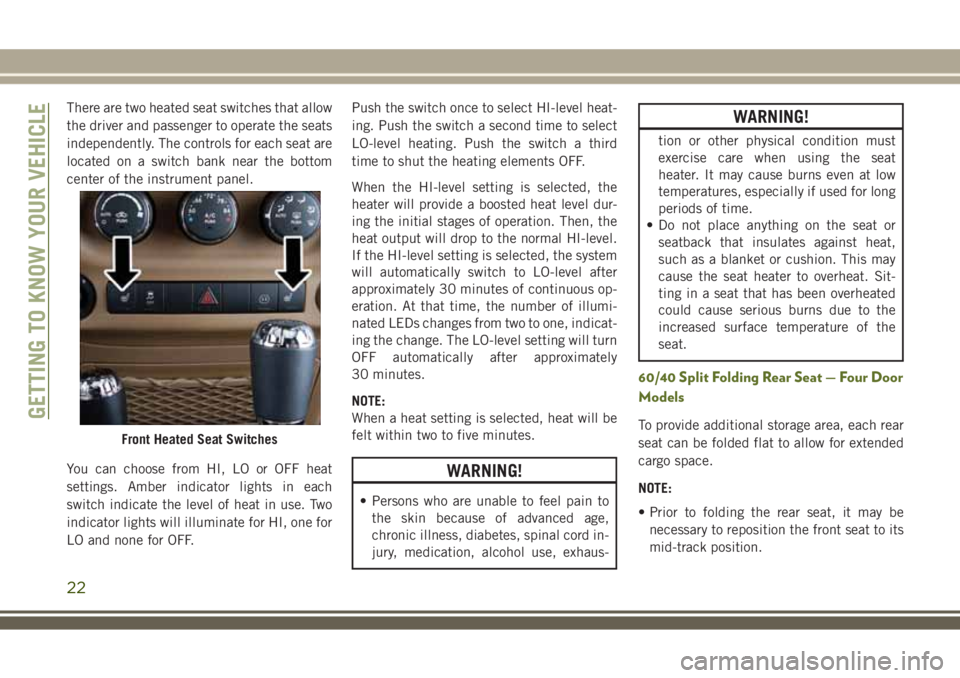
There are two heated seat switches that allow
the driver and passenger to operate the seats
independently. The controls for each seat are
located on a switch bank near the bottom
center of the instrument panel.
You can choose from HI, LO or OFF heat
settings. Amber indicator lights in each
switch indicate the level of heat in use. Two
indicator lights will illuminate for HI, one for
LO and none for OFF.Push the switch once to select HI-level heat-
ing. Push the switch a second time to select
LO-level heating. Push the switch a third
time to shut the heating elements OFF.
When the HI-level setting is selected, the
heater will provide a boosted heat level dur-
ing the initial stages of operation. Then, the
heat output will drop to the normal HI-level.
If the HI-level setting is selected, the system
will automatically switch to LO-level after
approximately 30 minutes of continuous op-
eration. At that time, the number of illumi-
nated LEDs changes from two to one, indicat-
ing the change. The LO-level setting will turn
OFF automatically after approximately
30 minutes.
NOTE:
When a heat setting is selected, heat will be
felt within two to five minutes.
WARNING!
• Persons who are unable to feel pain to
the skin because of advanced age,
chronic illness, diabetes, spinal cord in-
jury, medication, alcohol use, exhaus-
WARNING!
tion or other physical condition must
exercise care when using the seat
heater. It may cause burns even at low
temperatures, especially if used for long
periods of time.
• Do not place anything on the seat or
seatback that insulates against heat,
such as a blanket or cushion. This may
cause the seat heater to overheat. Sit-
ting in a seat that has been overheated
could cause serious burns due to the
increased surface temperature of the
seat.
60/40 Split Folding Rear Seat — Four Door
Models
To provide additional storage area, each rear
seat can be folded flat to allow for extended
cargo space.
NOTE:
• Prior to folding the rear seat, it may be
necessary to reposition the front seat to its
mid-track position.Front Heated Seat Switches
GETTING TO KNOW YOUR VEHICLE
22
Page 25 of 276
• Be sure that the front seats are fully upright
and positioned forward. This will allow the
rear seat to fold down easily.
• Remove the center head restraint. Failure
to do so will result in the head restraint
coming in contact with the center console.
WARNING!
• It is extremely dangerous to ride in a
cargo area, inside or outside of a vehicle.
In a collision, people riding in these
areas are more likely to be seriously
injured or killed.
• Do not allow people to ride in any area of
your vehicle that is not equipped with
seats and seat belts.
• Be sure everyone in your vehicle is in a
seat and using a seat belt properly.
To Fold Down The Rear Seat
Locate the release lever (upper outboard side
of seat), and lift it upward until the seatback
releases.
Slowly fold down the seatback.NOTE:
You may experience deformation in the seat
cushion from the seat belt buckles if the
seats are left folded for an extended period of
time. This is normal. By simply opening the
seats to the open position, the seat cushion
will return to its normal shape over time.
To Raise The Rear Seat
Raise the seatback and lock it into place, and
install center head restraint. If interference
from the cargo area prevents the seatback
from fully locking, you will have difficulty
returning the seat to its proper position.
NOTE:
If the rear seatback is not fully latched, the
center shoulder belt will not be able to be
extended for use. If you cannot extend the
center shoulder belt, make sure your seat-
back is fully latched.
WARNING!
Be certain that the seatback is securely
locked into position. If the seatback is not
securely locked into position the seat will
WARNING!
not provide the proper stability for child
seats and/or passengers. An improperly
latched seat could cause serious injury.
Front Passenger Easy Entry Seat — Two
Door Models
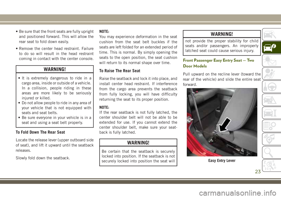
Pull upward on the recline lever (toward the
rear of the vehicle) and slide the entire seat
forward.
Easy Entry Lever
23
Page 26 of 276
To return the seat to a sitting position, rotate
the seatback upright until it locks and push
the seat rearward until the track locks.
NOTE:
• The front passenger seats have a track
memory, which returns the seat to just past
the halfway point of the track regardless of
its original position.
• The recliner and easy entry levers should
not be used during the automatic returning
of the seat to its sitting position.
Tip ‘n Slide Seats — Two Door Models
This feature allows the front seats to be
rotated toward the instrument panel to allow
easier entry into the rear seats.
Driver's Seat
Pull upward on the recline lever and bring the
seatback to its full forward position.
Rotate the entire seat assembly toward the
instrument panel.
Passenger Seat
In addition to Easy Entry, the front passenger
seat is also equipped with Tip ‘n Slide. This
feature allows for easier entry for rear passen-
gers.
Pull upward on the recline lever and slide the
entire seat forward (Easy Entry).
With the seat forward, pull the entire seat
assembly toward the instrument panel.
Removing The Rear Seat — Two Door
Models
NOTE:
• Prior to folding the rear seat, it may be
necessary to reposition the front seats.
• Be sure that the front seats are fully upright
and positioned forward. This will allow the
rear seat to fold down easily.
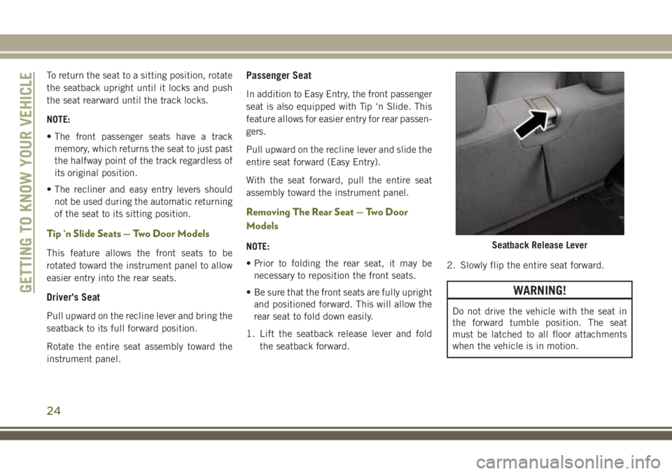
1. Lift the seatback release lever and fold
the seatback forward.2. Slowly flip the entire seat forward.
WARNING!
Do not drive the vehicle with the seat in
the forward tumble position. The seat
must be latched to all floor attachments
when the vehicle is in motion.
Seatback Release Lever
GETTING TO KNOW YOUR VEHICLE
24
Page 27 of 276
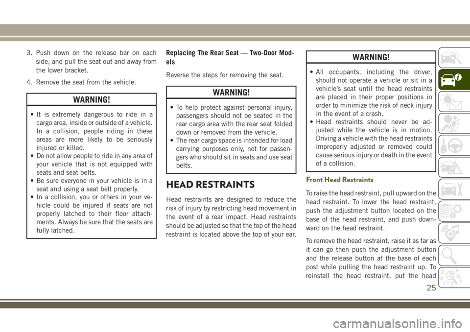
3. Push down on the release bar on each
side, and pull the seat out and away from
the lower bracket.
4. Remove the seat from the vehicle.
WARNING!
• It is extremely dangerous to ride in a
cargo area, inside or outside of a vehicle.
In a collision, people riding in these
areas are more likely to be seriously
injured or killed.
• Do not allow people to ride in any area of
your vehicle that is not equipped with
seats and seat belts.
• Be sure everyone in your vehicle is in a
seat and using a seat belt properly.
• In a collision, you or others in your ve-
hicle could be injured if seats are not
properly latched to their floor attach-
ments. Always be sure that the seats are
fully latched.
Replacing The Rear Seat — Two-Door Mod-
els
Reverse the steps for removing the seat.
WARNING!
• To help protect against personal injury,
passengers should not be seated in the
rear cargo area with the rear seat folded
down or removed from the vehicle.
• The rear cargo space is intended for load
carrying purposes only, not for passen-
gers who should sit in seats and use seat
belts.
HEAD RESTRAINTS
Head restraints are designed to reduce the
risk of injury by restricting head movement in
the event of a rear impact. Head restraints
should be adjusted so that the top of the head
restraint is located above the top of your ear.
WARNING!
• All occupants, including the driver,
should not operate a vehicle or sit in a
vehicle’s seat until the head restraints
are placed in their proper positions in
order to minimize the risk of neck injury
in the event of a crash.
• Head restraints should never be ad-
justed while the vehicle is in motion.
Driving a vehicle with the head restraints
improperly adjusted or removed could
cause serious injury or death in the event
of a collision.
Front Head Restraints
To raise the head restraint, pull upward on the
head restraint. To lower the head restraint,
push the adjustment button located on the
base of the head restraint, and push down-
ward on the head restraint.
To remove the head restraint, raise it as far as
it can go then push the adjustment button
and the release button at the base of each
post while pulling the head restraint up. To
reinstall the head restraint, put the head
25