service reset JEEP WRANGLER 2021 Owner handbook (in English)
[x] Cancel search | Manufacturer: JEEP, Model Year: 2021, Model line: WRANGLER, Model: JEEP WRANGLER 2021Pages: 276, PDF Size: 4.47 MB
Page 67 of 276
If any of these systems require service, the
OBD II system will turn on the Malfunction
Indicator Light (MIL). It will also store diag-
nostic codes and other information to assist
your service technician in making repairs.
Although your vehicle will usually be drivable
and not need towing, see your authorized
dealer for service as soon as possible.
CAUTION!
• Prolonged driving with the MIL on could
cause further damage to the emission
control system. It could also affect fuel
economy and driveability. The vehicle
must be serviced before any emissions
tests can be performed.
• If the MIL is flashing while the vehicle is
running, severe catalytic converter dam-
age and power loss will soon occur. Im-
mediate service is required.
Onboard Diagnostic System (OBD II)
Cybersecurity
Your vehicle is required to have an Onboard
Diagnostic system (OBD II) and a connection
port to allow access to information related tothe performance of your emissions controls.
Authorized service technicians may need to
access this information to assist with the
diagnosis and service of your vehicle and
emissions system.
WARNING!
• ONLY an authorized service technician
should connect equipment to the OBD II
connection port in order to diagnose or
service your vehicle.
• If unauthorized equipment is connected
to the OBD II connection port, such as a
driver-behavior tracking device, it may:
• Be possible that vehicle systems,
including safety related systems,
could be impaired or a loss of ve-
hicle control could occur that may
result in an accident involving seri-
ous injury or death.
• Access, or allow others to access,
information stored in your vehicle
systems, including personal infor-
mation.For further information, refer to “Cybersecu-
rity” in “Multimedia” in your Owner's
Manual.
Loose Fuel Filler Cap Message
After fuel is added, the vehicle diagnostic
system can determine if the fuel filler cap is
possibly loose, improperly installed, or dam-
aged. A “gASCAP” message will be displayed
in the odometer. Tighten the gas cap until a
"clicking" sound is heard. This is an indica-
tion that the gas cap is properly tightened.
Push the odometer reset button to turn the
message off. If the problem persists, the
message will appear the next time the vehicle
is started. This might indicate a damaged
cap. If the problem is detected twice in a row,
the system will turn on the MIL. Resolving the
problem will turn the MIL off.
65
Page 100 of 276
NOTE:
• Air bag covers may not be obvious in the
interior trim, but they will open during air
bag deployment.
• After any collision, the vehicle should be
taken to an authorized dealer immediately.
Enhanced Accident Response System
In the event of an impact, if the communica-
tion network remains intact, and the power
remains intact, depending on the nature of
the event, the ORC will determine whether to
have the Enhanced Accident Response Sys-
tem perform the following functions:
• Cut off fuel to the engine.
• Flash hazard lights as long as the battery
has power or until the hazard light button is
pressed. The hazard lights can be deacti-
vated by pressing the hazard light button.
• Turn on the interior lights, which remain on
as long as the battery has power.
• Unlock the power door locks.
Enhanced Accident Response System Reset
Procedure
In order to reset the Enhanced Accident Re-
sponse System functions after an event, the
ignition switch must be changed from igni-
tion START or ON/RUN to ignition OFF. Care-
fully check the vehicle for fuel leaks in the
engine compartment and on the ground near
the engine compartment and fuel tank before
resetting the system and starting the engine.
Maintaining Your Air Bag System
WARNING!
• Modifications to any part of the air bag
system could cause it to fail when you
need it. You could be injured if the air
bag system is not there to protect you.
Do not modify the components or wiring,
including adding any kind of badges or
stickers to the steering wheel hub trim
cover or the upper right side of the
instrument panel. Do not modify the
front bumper, vehicle body structure, or
add aftermarket side steps or running
boards.
WARNING!
• It is dangerous to try to repair any part of
the air bag system yourself. Be sure to
tell anyone who works on your vehicle
that it has an air bag system.
• Do not attempt to modify any part of your
air bag system. The air bag may inflate
accidentally or may not function prop-
erly if modifications are made. Take your
vehicle to an authorized dealer for any
air bag system service. If your seat, in-
cluding your trim cover and cushion,
needs to be serviced in any way (includ-
ing removal or loosening/tightening of
seat attachment bolts), take the vehicle
to your authorized dealer. Only manufac-
turer approved seat accessories may be
used. If it is necessary to modify the air
bag system for persons with disabilities,
contact your authorized dealer.
Event Data Recorder (EDR)
This vehicle is equipped with an event data
recorder (EDR). The main purpose of an EDR
is to record, in certain crash or near crash-
like situations, such as an air bag deployment
SAFETY
98
Page 138 of 276
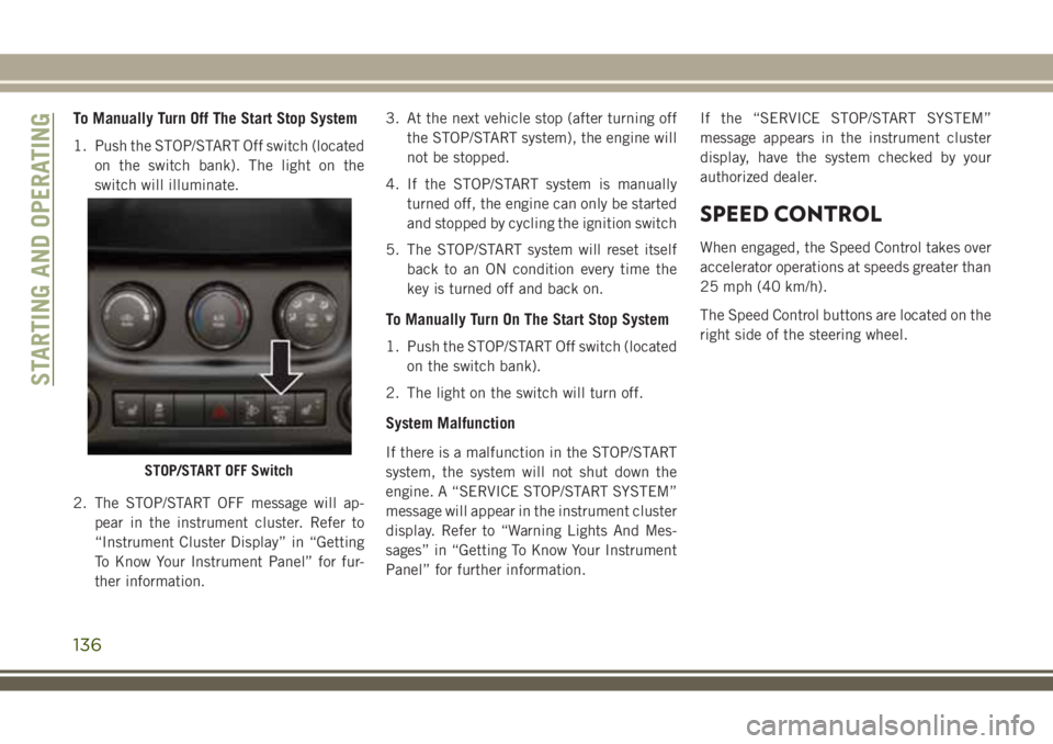
To Manually Turn Off The Start Stop System
1. Push the STOP/START Off switch (located
on the switch bank). The light on the
switch will illuminate.
2. The STOP/START OFF message will ap-
pear in the instrument cluster. Refer to
“Instrument Cluster Display” in “Getting
To Know Your Instrument Panel” for fur-
ther information.3. At the next vehicle stop (after turning off
the STOP/START system), the engine will
not be stopped.
4. If the STOP/START system is manually
turned off, the engine can only be started
and stopped by cycling the ignition switch
5. The STOP/START system will reset itself
back to an ON condition every time the
key is turned off and back on.
To Manually Turn On The Start Stop System
1. Push the STOP/START Off switch (located
on the switch bank).
2. The light on the switch will turn off.
System Malfunction
If there is a malfunction in the STOP/START
system, the system will not shut down the
engine. A “SERVICE STOP/START SYSTEM”
message will appear in the instrument cluster
display. Refer to “Warning Lights And Mes-
sages” in “Getting To Know Your Instrument
Panel” for further information.If the “SERVICE STOP/START SYSTEM”
message appears in the instrument cluster
display, have the system checked by your
authorized dealer.
SPEED CONTROL
When engaged, the Speed Control takes over
accelerator operations at speeds greater than
25 mph (40 km/h).
The Speed Control buttons are located on the
right side of the steering wheel.
STOP/START OFF Switch
STARTING AND OPERATING
136
Page 172 of 276
SCHEDULED SERVICING
Scheduled Servicing — Gasoline Engine
The scheduled services listed in this manual
must be done at the times or mileages speci-
fied to protect your vehicle warranty and
ensure the best vehicle performance and re-
liability. More frequent maintenance may be
needed for vehicles in severe operating con-
ditions, such as dusty areas and very short
trip driving. Inspection and service should
also be done anytime a malfunction is sus-
pected.
The oil change indicator system will remind
you that it is time to take your vehicle in for
scheduled maintenance.
On non-instrument cluster display equipped
vehicles, “CHANgE OIL” will flash in the
instrument cluster odometer and a single
chime will sound, indicating that an oil
change is necessary.The oil change indicator message will illumi-
nate approximately 7,000 miles
(11,200 km) after the most recent oil change
was performed. Have your vehicle serviced as
soon as possible, within 500 miles (800 km).
However, an earlier oil change at 4,500 miles
(7,500 km) may be required if the vehicle is
operated under “Severe Duty Conditions”
later in this section.
NOTE:
• The oil change indicator message will not
monitor the time since the last oil change.
Change your vehicle's oil if it has been
6 months since your last oil change even if
the oil change indicator message is NOT
illuminated.
• Change your engine oil more often if you
drive your vehicle off-road for an extended
period of time.
• Under no circumstances should oil change
intervals exceed 7,500 miles (12,000 km)
or 6 months, whichever comes first.
Your authorized dealer will reset the oil
change indicator message after completing
the scheduled oil change.Once A Month Or Before A Long Trip
• Check the engine oil level about five min-
utes after a fully warmed engine is shut off.
Checking the oil level while the vehicle is
on level ground will improve the accuracy of
the oil level reading. Add oil only when the
level is at or below the ADD or MIN mark.
• Check the windshield washer solvent and
add if required.
• Check tire pressure and look for unusual
wear or damage. Rotate tires at the first
sign of irregular wear, even if it occurs
before the oil indicator system turns on.
• Inspect the battery and clean and tighten
the terminals as required.
• Check the fluid levels of coolant reservoir,
automatic transmission, brake master cyl-
inder and power steering and fill as needed.
• Check all lights and other electrical items
for correct operation.
SERVICING AND MAINTENANCE
170
Page 178 of 276
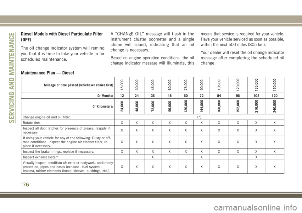
Diesel Models with Diesel Particulate Filter
(DPF)
The oil change indicator system will remind
you that it is time to take your vehicle in for
scheduled maintenance.A “CHANgE OIL” message will flash in the
instrument cluster odometer and a single
chime will sound, indicating that an oil
change is necessary.
Based on engine operation conditions, the oil
change indicator message will illuminate, thismeans that service is required for your vehicle.
Have your vehicle serviced as soon as possible,
within the next 500 miles (805 km).
Your dealer will reset the oil change indicator
message after completing the scheduled oil
change.
Maintenance Plan — Diesel
Mileage or time passed (whichever comes first)15,000
30,000
45,000
60,000
75,000
90,000
105,00
120,000
135,000
150,000
Or Months: 12 24 36 48 60 72 84 96 108 120
Or Kilometers:
24,000
48,000
72,000
96,000
120,000
144,000
168,000
192,000
216,000
240,000
Change engine oil and oil filter.(*)
Rotate tires X X X X X X X X X X
Inspect all door latches for presence of grease, reapply if
necessary.XX X X X X X X X X
If using your vehicle for any of the following: Dusty or off-
road conditions. Inspect the engine air cleaner filter, re-
place if necessary.XX X X X X X X X X
Inspect the brake linings, replace if necessary. X X X X X X X X X X
Inspect exhaust system. X X X
Visually inspect condition of: exterior bodywork, underbody
protection, pipes and hoses (exhaust - fuel system -
brakes), rubber elements (boots, sleeves, bushings, etc.).XX X X X X X X X X
SERVICING AND MAINTENANCE
176
Page 187 of 276
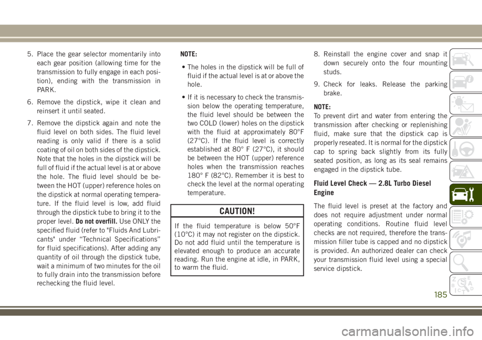
5. Place the gear selector momentarily into
each gear position (allowing time for the
transmission to fully engage in each posi-
tion), ending with the transmission in
PARK.
6. Remove the dipstick, wipe it clean and
reinsert it until seated.
7. Remove the dipstick again and note the
fluid level on both sides. The fluid level
reading is only valid if there is a solid
coating of oil on both sides of the dipstick.
Note that the holes in the dipstick will be
full of fluid if the actual level is at or above
the hole. The fluid level should be be-
tween the HOT (upper) reference holes on
the dipstick at normal operating tempera-
ture. If the fluid level is low, add fluid
through the dipstick tube to bring it to the
proper level.Do not overfill.Use ONLY the
specified fluid (refer to "Fluids And Lubri-
cants" under “Technical Specifications”
for fluid specifications). After adding any
quantity of oil through the dipstick tube,
wait a minimum of two minutes for the oil
to fully drain into the transmission before
rechecking the fluid level.NOTE:
• The holes in the dipstick will be full of
fluid if the actual level is at or above the
hole.
• If it is necessary to check the transmis-
sion below the operating temperature,
the fluid level should be between the
two COLD (lower) holes on the dipstick
with the fluid at approximately 80°F
(27°C). If the fluid level is correctly
established at 80° F (27°C), it should
be between the HOT (upper) reference
holes when the transmission reaches
180° F (82°C). Remember it is best to
check the level at the normal operating
temperature.
CAUTION!
If the fluid temperature is below 50°F
(10°C) it may not register on the dipstick.
Do not add fluid until the temperature is
elevated enough to produce an accurate
reading. Run the engine at idle, in PARK,
to warm the fluid.8. Reinstall the engine cover and snap it
down securely onto the four mounting
studs.
9. Check for leaks. Release the parking
brake.
NOTE:
To prevent dirt and water from entering the
transmission after checking or replenishing
fluid, make sure that the dipstick cap is
properly reseated. It is normal for the dipstick
cap to spring back slightly from its fully
seated position, as long as its seal remains
engaged in the dipstick tube.
Fluid Level Check — 2.8L Turbo Diesel
Engine
The fluid level is preset at the factory and
does not require adjustment under normal
operating conditions. Routine fluid level
checks are not required, therefore the trans-
mission filler tube is capped and no dipstick
is provided. An authorized dealer can check
your transmission fluid level using a special
service dipstick.
185
Page 264 of 276
AirBag .............58, 92, 113
Automatic Headlights..........29
Back-Up.................149
Brake Assist Warning..........75
Bulb Replacement.......146, 147
Center Mounted Stop.........149
Cruise...................64
Daytime Running............29
Dimmer Switch, Headlight.......29
Exterior..................114
Fog .................29, 148
Hazard Warning Flasher........146
Headlight Leveling............30
Headlights.............28, 147
Headlight Switch.............28
High Beam................29
High Beam/Low Beam Select.....29
Hill Descent Control Indicator.....76
Instrument Cluster............28
Malfunction Indicator
(Check Engine)..............61
Passing..................29
Rear Fog.................148
Rear Servicing.............149
Rear Tail Lamps............149
Seat Belt Reminder...........60
Security Alarm..............61Service..............146, 147
Side Marker...............149
Tire Pressure Monitoring (TPMS) . . .62
Traction Control.............75
Turn Signal . . .29, 64, 114, 148, 149
Warning (Instrument Cluster
Description)................64
Locking Axle.................132
Lug Nuts...................208
Maintenance Free Battery.........186
Maintenance Schedule.......170, 175
Diesel..................175
Malfunction Indicator Light
(Check Engine)...............61
Manual Transmission........123, 184
Fluid Level Check...........184
Lubricant Selection..........211
Shift Speeds.............
.124
Media Center Radio.............220
Memory Feature (Memory Seat)......21
Memory Seat..................21
Memory Seats And Radio..........21
Mirrors.....................28
Heated...................28
Modifications/Alterations, Vehicle......4
Monitor, Tire Pressure System.......77Mopar.....................212
Mopar Accessories.............212
Navigation..................229
Navigation System (Uconnect GPS) . . .229
Navigation Voice Prompt Volume.....229
New Vehicle Break-In Period.......121
Occupant Restraints.............84
Octane Rating, Gasoline (Fuel)......209
Oil Change Indicator..........58, 176
Oil Change Indicator, Reset.....58, 176
Oil, Engine
Capacity.................210
Change Interval..............58
Dipstick.................182
Pressure Warning Light.........60
Recommendation...........210
Viscosity.................210
Oil Pressure Light...............60
Onboard Diagnostic System.........64
Operating Precautions............64
Operator Manual (Owner's Manual).....4
Outlet
Power...................52
Overheating, Engine............163
INDEX
262