4WD JEEP WRANGLER 2023 User Guide
[x] Cancel search | Manufacturer: JEEP, Model Year: 2023, Model line: WRANGLER, Model: JEEP WRANGLER 2023Pages: 396, PDF Size: 25.15 MB
Page 157 of 396
STARTING AND OPERATING155
If ACC is set when the vehicle speed is below 20 mph
(32 km/h), the set speed will default to 20 mph
(32 km/h).
NOTE:Fixed Speed Cruise Control cannot be set below 20 mph
(32 km/h).
If either system is set when the vehicle speed is above
20 mph (32 km/h), the set speed shall be the current speed of the vehicle.
On vehicles equipped with a manual transmission, the
ACC system cannot be set when the vehicle speed is below
20 mph (32 km/h) or when the vehicle is in FIRST gear.
NOTE:
Keeping your foot on the accelerator pedal can cause
the vehicle to continue to accelerate beyond the set
speed. If this occurs, the message “DRIVER OVERRIDE”
will display in the instrument cluster display.
If you continue to accelerate beyond the set speed
while ACC is enabled, the system will not be controlling
the distance between your vehicle and the vehicle
ahead. The vehicle speed will only be determined by
the position of the accelerator pedal.
To Cancel
The following conditions cancel the ACC or Fixed Speed
Cruise Control systems:
The brake pedal is applied
The CANC button is pushed
The Anti-Lock Brake System (ABS) activates
The gear selector is removed from the DRIVE position
The Electronic Stability Control/Traction Control
System (ESC/TCS) activates
The vehicle parking brake is applied
The braking temperature exceeds normal range (over -
heated)
The Trailer Sway Control (TSC) activates
The vehicle speed is less than 15 mph (24 km/h)
(manual transmission only)
The clutch is pressed for more than 10 seconds
(manual transmission only)
The vehicle is placed in NEUTRAL for more than
10 seconds (manual transmission only)
The driver shifts to FIRST gear (manual transmission
only)
The following conditions will only cancel the ACC system:
Driver seat belt is unbuckled at low speeds
Driver door is opened at low speeds
To Turn Off
The system will turn off and erase the set speed in
memory if:
The Adaptive Cruise Control (ACC) on/off button is
pushed
The Fixed Speed Cruise Control on/off button is pushed
The ignition is placed in the OFF position
4WD Low is engaged
To Resume
If there is a set speed in the memory, push the RES button
and then remove your foot from the accelerator pedal. The
instrument cluster display will show the last set speed. Resume can be used at any speed above 20 mph
(32 km/h) when only Fixed Speed Cruise Control is being
used.
Resume can be used at any speed above 0 mph (0 km/h)
when ACC is active.
NOTE:
While in ACC mode, when the vehicle comes to a
complete stop longer than two seconds, the system will
cancel. The driver will have to apply the brakes to keep
the vehicle at a standstill.
ACC cannot be resumed if there is a stationary vehicle
in front of your vehicle in close proximity.
To Vary The Speed Setting
To Increase Or Decrease The Set Speed
After setting a speed, you can increase the set speed by
pushing the SET (+) button, or decrease speed by pushing
the SET (-) button.
WARNING!
The Resume function should only be used if traffic and
road conditions permit. Resuming a set speed that is
too high or too low for prevailing traffic and road condi -
tions could cause the vehicle to accelerate or deceler -
ate too sharply for safe operation. Failure to follow
these warnings can result in a collision and death or
serious personal injury.
4
23_JL_OM_EN_USC_t.book Page 155
Page 164 of 396
162STARTING AND OPERATING
The vehicle is close to the obstacle when the warning display shows one flashing arc and sounds a continuous tone. The following chart shows the warning alert operation when the
system is detecting an obstacle:
NOTE:ParkSense will reduce the volume of the radio, if on, when
the system is sounding an audio tone.
ENABLING AND DISABLING PARKSENSE
ParkSense can be enabled and disabled with
the ParkSense switch located below the
Uconnect display.
When the ParkSense switch is pushed to disable the
system, the instrument cluster display
Úpage 108 will
show the “PARKSENSE OFF” message for approximately
five seconds. When the gear selector is moved to
REVERSE and the system is disabled, the instrument
cluster display will show the “PARKSENSE OFF” message
for as long as the vehicle is in REVERSE (Not in 4WD Low). The ParkSense switch LED will be on when ParkSense is
disabled or requires service. The ParkSense switch LED
will be off when the system is enabled. If the ParkSense
switch is pushed, and requires service, the ParkSense
switch LED will blink momentarily, and then the LED will
remain on.
SERVICE THE PARKSENSE REAR PARK
A
SSIST SYSTEM
During vehicle start up, when the ParkSense Rear Park
Assist System has detected a faulted condition, the
instrument cluster display will actuate a single chime,
once per ignition cycle, and it will display the “PARKSENSE
UNAVAILABLE WIPE REAR SENSORS” or the “PARKSENSE
UNAVAILABLE SERVICE REQUIRED” message. When the gear selector is moved to REVERSE and the
system has detected a faulted condition, the instrument
cluster display will show the "PARKSENSE UNAVAILABLE
WIPE REAR SENSORS" or "PARKSENSE UNAVAILABLE
SERVICE REQUIRED" message for as long as the vehicle is
in REVERSE. Under this condition, ParkSense will not
operate.
If “PARKSENSE UNAVAILABLE WIPE REAR SENSORS”
appears in the instrument cluster display, make sure the
outer surface and the underside of the rear fascia/
bumper is clean and clear of snow, ice, mud, dirt or other
obstruction and then cycle the ignition. If the message
continues to appear, see an authorized dealer.
If “PARKSENSE UNAVAILABLE SERVICE REQUIRED”
appears in the instrument cluster display, see an
authorized dealer.
WARNING ALERTS
Rear Distance
(inches/cm) Greater than
79 inches (200 cm) 79-59 inches
(200-150 cm) 59-47 inches
(150-120 cm) 47-39 inches
(120-100 cm) 39-25 inches
(100-65 cm) 25-12 inches
(65-30 cm) Less than
12 inches (30 cm)
Arcs — Left NoneNone NoneNoneNone2nd Flashing 1st Flashing
Arcs — Center None6th Solid 5th Solid4th Solid 3rd Flashing 2nd Flashing 1st Flashing
Arcs — Right NoneNone NoneNoneNone2nd Flashing 1st Flashing
Audible Alert Chime None Single 1/2 Second
Tone
(for rear center only) Slow
(for rear center only) Slow
(for rear center only) Fast
(for rear center only) Fast
Continuous
Radio Volume Reduced No
Yes YesYesYes YesYes
23_JL_OM_EN_USC_t.book Page 162
Page 167 of 396
STARTING AND OPERATING165
NOTE:The system will stay active while in 4WD Low.
The TrailCam system has programmable settings that may
be selected through the Uconnect system
Úpage 184.
Manual Activation Of The TrailCam
TrailCam view can be activated via the below methods:
Press the FWD Camera button on the controls screen.
Press the Forward Facing Camera button on the apps
menu.
Press the TrailCam button on the Off Road Pages.
Press the Off Road+ button when “Auto Launch Off
Road+” (if equipped) has been selected under camera
settings.
The TrailCam view can also be activated by pressing the icon on the Back Up Camera view. The Back Up
Camera view can also be activated by pressing the
icon on the TrailCam view.
When the vehicle is shifted out of REVERSE with Camera
Delay turned off and TrailCam view is active, the TrailCam
mode is exited and the previous screen appears again.
When the vehicle is shifted out of REVERSE with Camera
Delay turned on and the TrailCam view is active, the
TrailCam image will be displayed for up to 10 seconds
unless the vehicle speed exceeds 8 mph (13 km/h), the
transmission is shifted into PARK, the ignition is placed in
the OFF position, or the touchscreen X button to disable
display of the TrailCam view is pressed.
Whenever the TrailCam image is activated through the
Manual Activation Methods, and the vehicle speed is
greater than or equal to 8 mph (13 km/h), a display timer for the image is initiated. The image will continue to be
displayed until the display timer exceeds 10 seconds.
NOTE:
If the vehicle speed remains below 8 mph (13 km/h)
while in 2WD or 4WD High, the TrailCam image will be
displayed continuously until deactivated via the touch -
screen X button, the transmission is shifted into PARK,
or the ignition is placed in the OFF position.
The touchscreen X button to disable the display of the
camera image is made available ONLY when the
vehicle is not in REVERSE.
The TrailCam view will stay active regardless of the
vehicle speed and time while in 4WD Low.
Cleaning The TrailCam
Press and hold the Clean Camera button located on the
TrailCam view to wash the TrailCam. Washer fluid will stop
when the button is released.
The camera can be washed up to 20 seconds at a time
while holding the button.
The Clean Camera system is not available when wind -
shield washing is in process.
When enabled, active dynamic tire lines are projected on
the ground plane of the TrailCam view based on the
steering wheel position.
REFUELING THE VEHICLE — GASOLINE
ENGINE (IF EQUIPPED)
FUEL FILLER CAP
The fuel filler cap is located on the driver's side of the
vehicle. If the fuel filler cap is lost or damaged, be sure the
replacement cap is the correct one for this vehicle.
1. Open the fuel filler door.
Fuel Filler Door
2. Remove the fuel cap by rotating it counterclockwise.
Fuel Filler Cap
3. Fully insert the fuel nozzle into the filler pipe.
4
23_JL_OM_EN_USC_t.book Page 165
Page 178 of 396
176STARTING AND OPERATING
(Continued)
(Continued)
RECREATIONAL TOWING (BEHIND MOTORHOME)
TOWING THIS VEHICLE BEHIND ANOTHER VEHICLE
RECREATIONAL TOWING —
F
OUR-WHEEL DRIVE MODELS
NOTE:The transfer case must be shifted into (N) Neutral, auto -
matic transmission must be in PARK, and manual trans -
mission must be in gear (NOT in NEUTRAL) for recreational
towing.
Towing Condition Wheels OFF the Ground Four-Wheel Drive Models
Flat Tow NONESee Instructions
Automatic transmission in PARK.
Manual transmission in gear (NOT in NEUTRAL [N]).
Transfer case in (N) Neutral.
Tow in forward direction.
Dolly Tow Front
NOT ALLOWED
Rear NOT ALLOWED
On Trailer ALLOK
NOTE:When towing your vehicle, always follow applicable state and provincial laws. Contact state and provincial Highway Safety offices for additional details.
CAUTION!
DO NOT dolly tow any 4WD vehicle. Towing with only
one set of wheels on the ground (front or rear) will
cause severe transmission and/or transfer case
damage. Tow with all four wheels either ON the
ground, or OFF the ground (using a vehicle trailer).
Tow only in the forward direction. Towing this vehicle
backwards can cause severe damage to the transfer
case.
Automatic transmissions must be placed in PARK for
recreational towing.Manual transmissions must be placed in gear (not in
NEUTRAL) for recreational towing.
Before recreational towing, perform the procedure
outlined under “Shifting Into (N) Neutral” to be
certain that the transfer case is fully in (N) Neutral.
Otherwise, internal damage will result.
Towing this vehicle in violation of the above require -
ments can cause severe transmission and/or transfer
case damage. Damage from improper towing is not
covered under the New Vehicle Limited Warranty.
CAUTION!
23_JL_OM_EN_USC_t.book Page 176
Page 243 of 396
MULTIMEDIA241
repositioning the mobile phone, it is recommended that
the volume be turned down or off during mobile phone
operation when not using the Uconnect system.
REGULATORY AND SAFETY
I
NFORMATION
US/CANADA
Exposure to Radio Frequency Radiation
The radiated output power of the internal wireless radio is
far below the FCC and IC radio frequency exposure limits.
Nevertheless, the wireless radio will be used in such a
manner that the radio is 8 inches (20 cm) or further from
the human body.
The internal wireless radio operates within guidelines
found in radio frequency safety standards and
recommendations, which reflect the consensus of the
scientific community.
The radio manufacturer believes the internal wireless
radio is safe for use by consumers. The level of energy
emitted is far less than the electromagnetic energy
emitted by wireless devices such as mobile phones.
However, the use of wireless radios may be restricted in
some situations or environments, such as aboard
airplanes. If you are unsure of restrictions, you are
encouraged to ask for authorization before turning on the
wireless radio
Úpage 381.
OFF-ROAD PAGES — IF EQUIPPED
If your vehicle is equipped with Off-Road Pages, it will
provide you vehicle status information while operating on
off-road conditions. It supplies information relating to the
status of the drivetrain, transfer case, coolant/oil gauges,
pitch and roll of the vehicle, and access to the trailcam
system.
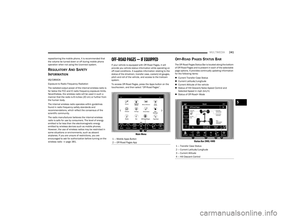
To access Off-Road Pages, press the Apps button on the
touchscreen, and then select “Off-Road Pages”.
Main Menu
OFF-ROAD PAGES STATUS BAR
The Off-Road Pages Status Bar is located along the bottom
of Off-Road Pages and is present in each of the selectable
page options. It provides continually updating information
for the following items:
Current Transfer Case Status
Current Latitude/Longitude
Current Altitude of the vehicle
Status of Hill Descent/Selec-Speed Control and
Selected Speed in mph (km/h)
Status of Off-Road+ Mode
Status Bar 2WD/4WD
1 — Mobile Apps Button
2 — Off-Road Pages App
1 — Transfer Case Status
2 — Current Latitude/Longitude
3 — Current Altitude
4 — Hill Descent Control
5
23_JL_OM_EN_USC_t.book Page 241
Page 244 of 396
242MULTIMEDIA
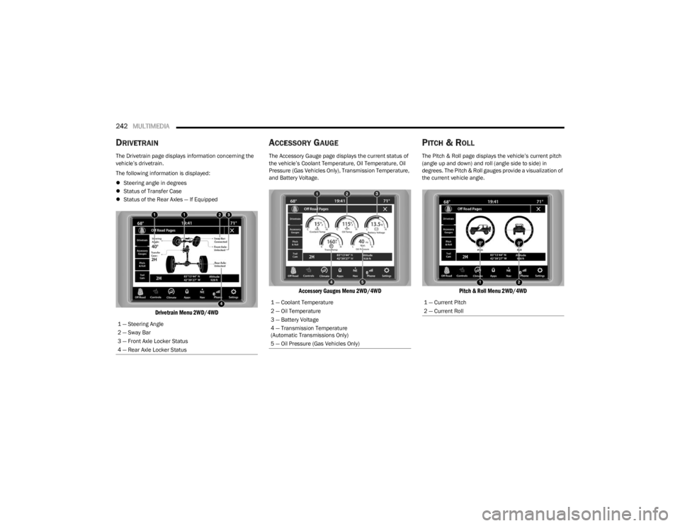
DRIVETRAIN
The Drivetrain page displays information concerning the
vehicle’s drivetrain.
The following information is displayed:
Steering angle in degrees
Status of Transfer Case
Status of the Rear Axles — If Equipped
Drivetrain Menu 2WD/4WD
ACCESSORY GAUGE
The Accessory Gauge page displays the current status of
the vehicle’s Coolant Temperature, Oil Temperature, Oil
Pressure (Gas Vehicles Only), Transmission Temperature,
and Battery Voltage.
Accessory Gauges Menu 2WD/4WD
PITCH & ROLL
The Pitch & Roll page displays the vehicle’s current pitch
(angle up and down) and roll (angle side to side) in
degrees. The Pitch & Roll gauges provide a visualization of
the current vehicle angle.
Pitch & Roll Menu 2WD/4WD
1 — Steering Angle
2 — Sway Bar
3 — Front Axle Locker Status
4 — Rear Axle Locker Status
1 — Coolant Temperature
2 — Oil Temperature
3 — Battery Voltage
4 — Transmission Temperature
(Automatic Transmissions Only)
5 — Oil Pressure (Gas Vehicles Only)1 — Current Pitch
2 — Current Roll
23_JL_OM_EN_USC_t.book Page 242
Page 250 of 396

248SAFETY
Each time the ignition is place in the ON position, the
ESC system will be on even if it was turned off previ -
ously.
The ESC system will make buzzing or clicking sounds
when it is active. This is normal; the sounds will stop
when ESC becomes inactive following the maneuver
that caused the ESC activation.
Hill Descent Control (HDC) — If Equipped
HDC is intended for low speed off-road driving while in
4WD Low. HDC maintains vehicle speed while descending
hills during various driving situations. HDC controls vehicle
speed by actively controlling the brakes.
HDC has three states:
1. Off (feature is not enabled and will not activate).
2. Enabled (feature is enabled and ready but activation
conditions are not met, or driver is actively overriding
with brake or throttle application).
3. Active (feature is enabled and actively controlling vehicle speed).
Enabling HDC
HDC is enabled by pushing the HDC switch, but the
following conditions must also be met to enable HDC:
The driveline is in 4WD Low.
The vehicle speed is below 5 mph (8 km/h).
The parking brake is released.
The driver door is closed. (If doors are attached, then
door must be closed. If doors are detached, then driver
seat belt must be buckled.) Activating HDC
Once HDC is enabled it will activate automatically if driven
down a grade of sufficient magnitude. The set speed for
HDC is selectable by the driver, and can be adjusted by
using the gear shift +/-. The following summarizes the
HDC set speeds:
HDC Target Set Speeds
P = No set speed. HDC may be enabled but will not acti -
vate
R = 0.6 mph (1 km/h)
N = 1.2 mph (2 km/h)
D = 0.6 mph (1 km/h)
1st = 0.6 mph (1 km/h)
2nd = 1.2 mph (2 km/h)
3rd = 1.8 mph (3 km/h)
4th = 2.5 mph (4 km/h)
5th = 3.1 mph (5 km/h)
6th = 3.7 mph (6 km/h)
7th = 4.3 mph (7 km/h)
8th = 5.0 mph (8 km/h)
9th = 5.6 mph (9 km/h) – If Equipped
NOTE:During HDC the +/- shifter input is used for HDC target
speed selection, but will not affect the gear chosen by the
transmission. When actively controlling HDC the trans -
mission will shift appropriately for the driver-selected set
speed and corresponding driving conditions.
Driver Override
The driver may override HDC activation with throttle or
brake application at any time. Deactivating HDC
HDC will be deactivated but remain available if any of the
following conditions occur:
Driver overrides HDC set speed with throttle or brake
application.
Vehicle speed exceeds 20 mph (32 km/h) but remains
below 40 mph (64 km/h).
Vehicle is on a downhill grade of insufficient magni-
tude, is on level ground, or is on an uphill grade.
Vehicle is shifted to PARK.
Disabling HDC
HDC will be deactivated and disabled if any of the
following conditions occur:
The driver pushes the HDC switch.
The driveline is shifted out of 4WD Low.
The parking brake is applied.
The driver door opens. (Driver door opens if doors are
attached or driver seat belt is unbuckled if doors are
detached.)
The vehicle is driven greater than 20 mph (32 km/h)
for greater than 70 seconds.
The vehicle is driven greater than 40 mph (64 km/h)
(HDC exits immediately).
HDC detects excessive brake temperature.
23_JL_OM_EN_USC_t.book Page 248
Page 252 of 396

250SAFETY
Ready Alert Braking (RAB)
RAB may reduce the time required to reach full braking
during emergency braking situations. It anticipates when
an emergency braking situation may occur by monitoring
how fast the throttle is released by the driver. The
Electronic Brake Controller (EBC) will prepare the brake
system for a panic stop.
Selec-Speed Control (SSC) — If Equipped
SSC is intended for off-road driving in 4WD Low
only. SSC maintains vehicle speed by actively
controlling engine torque and brakes.
SSC has three states:
1. Off (feature is not enabled and will not activate)
2. Enabled (feature is enabled and ready but activation conditions are not met, or driver is actively overriding
with brake or throttle application)
3. Active (feature is enabled and actively controlling vehicle speed)
Enabling SSC
SSC is enabled by pushing the SSC switch, but the
following conditions must also be met to enable SSC:
The driveline is in 4WD Low.
The vehicle speed is below 5 mph (8 km/h).
The parking brake is released.
The driver door is closed (If doors are attached, the
door must be closed. If doors are detached, the driver
seat belt must be buckled).
The driver is not applying throttle. Activating SSC
Once SSC is enabled it will activate automatically once the
following conditions are met:
The driver releases the throttle.
The driver releases the brake.
The driver seat belt is buckled.
The transmission is in any selection other than PARK.
Your vehicle speed is below 20 mph (32 km/h).
The driver door is closed. (If doors are attached, the
door must be closed. If doors are detached, the driver
seat belt must be buckled).
The set speed for SSC is selectable by the driver, and can
be adjusted by using the gear shift +/-. Additionally, the
SSC set speed may be reduced when climbing a grade and
the level of set speed reduction depends on the
magnitude of grade. The following summarizes the SSC
set speeds:
SSC Target Set Speeds
1st = 0.6 mph (1 km/h)
2nd = 1.2 mph (2 km/h)
3rd = 1.8 mph (3 km/h)
4th = 2.5 mph (4 km/h)
5th = 3.1 mph (5 km/h)
6th = 3.7 mph (6 km/h)
7th = 4.3 mph (7 km/h)
8th = 5 mph (8 km/h)
9th = 5.6 mph (9 km/h) — if equipped
REVERSE = 0.6 mph (1 km/h)
NEUTRAL = 1.2 mph (2 km/h)
PARK = SSC remains enabled but not active SSC Target Set Speeds — If Equipped With Off Road+
1st = 0.6 mph (1 km/h)
2nd = 0.9 mph (1.5 km/h)
3rd = 1.2 mph (2 km/h)
4th = 1.5 mph (2.5 km/h)
5th = 1.8 mph (3 km/h)
6th = 2.5 mph (4 km/h)
7th = 3.7 mph (6 km/h)
8th = 5 mph (8 km/h)
REVERSE = 0.6 mph (1 km/h)
NEUTRAL = 1.2 mph (2 km/h)
PARK = SSC remains enabled but not active
NOTE:
During SSC, the +/- gear selector input is used for SSC
target speed selection but will not affect the gear
chosen by the transmission. While actively controlling
SSC, the transmission will shift appropriately for the
driver-selected set speed and corresponding driving
conditions.
SSC operation is influenced by Off Road+ drive mode if
active. The differences may be notable to the driver as
a varying level of aggressiveness.
Driver Override
The driver may override SSC activation with throttle or
brake application at any time.
23_JL_OM_EN_USC_t.book Page 250
Page 253 of 396
SAFETY251
Deactivating SSC
SSC will be deactivated but remain available if any of the
following conditions occur:
The driver overrides SSC set speed with throttle or
brake application.
The vehicle speed exceeds 20 mph (32 km/h) but
remains below 40 mph (64 km/h).
The vehicle is shifted into PARK.
Disabling SSC
SSC will deactivate and be disabled if any of the following
conditions occur:
The driver pushes the SSC switch.
The driveline is shifted out of the 4WD Low.
The parking brake is applied.
The vehicle is driven greater than 20 mph (32 km/h)
for greater than 70 seconds.
The vehicle is driven greater than 40 mph (64 km/h).
SSC will exist immediately.
The driver door opens. (Driver door opens if doors are
attached or driver seat belt is unbuckled if doors are
detached).
Feedback To The Driver
The instrument cluster has an SSC icon and the SSC
switch has a lamp that offers feedback to the driver about
the state SSC is in.
The cluster icon and switch lamp will illuminate and
remain on solid when SSC is enabled or activated.
These are the normal operating conditions for SSC.
The cluster icon and switch lamp will flash for several
seconds then extinguish when the driver pushes the
SSC switch but enabled conditions are not met.
The cluster icon and switch lamp will flash for several
seconds then extinguish when SSC disables due to
excess speed.
The cluster icon and switch lamp will flash then extin -
guish when SSC deactivates due to overheated brakes.
Traction Control System (TCS)
TCS monitors the amount of wheel spin of each of the
driven wheels. If wheel spin is detected, the TCS may apply
brake pressure to the spinning wheel(s) and/or reduce
engine power to provide enhanced acceleration and
stability. A feature of the TCS, Brake Limited Differential
(BLD) functions similarly to a limited slip differential and
controls the wheel spin across a driven axle. If one wheel
on a driven axle is spinning faster than the other, the
system will apply the brake of the spinning wheel. This will
allow more engine torque to be applied to the wheel that
is not spinning. BLD may remain enabled even if TCS and
Electronic Stability Control (ESC) are in reduced modes.
Trailer Sway Control (TSC)
TSC uses sensors in the vehicle to recognize an
excessively swaying trailer and will take the appropriate
actions to attempt to stop the sway.
NOTE:TSC cannot stop all trailers from swaying. Always use
caution when towing a trailer and follow the trailer tongue
weight recommendations
Úpage 170.
When TSC is functioning, the ESC Activation/Malfunction
Indicator Light will flash, the engine power may be reduced
and you may feel the brakes being applied to individual
wheels to attempt to stop the trailer from swaying. TSC is
disabled when the ESC system is in the “Partial Off” or
“Full Off” modes.
WARNING!
SSC is only intended to assist the driver in controlling
vehicle speed when driving in off-road conditions. The
driver must remain attentive to the driving conditions
and is responsible for maintaining a safe vehicle speed.
WARNING!
If TSC activates while driving, slow the vehicle down,
stop at the nearest safe location, and adjust the trailer
load to eliminate trailer sway.6
23_JL_OM_EN_USC_t.book Page 251
Page 305 of 396
IN CASE OF EMERGENCY303
TOWING A DISABLED VEHICLE
This section describes procedures for towing a disabled vehicle using a commercial towing service.
If the transmission and drivetrain are operable, disabled 4x4 vehicles may also be towed as described
Úpage 176.
Proper towing or lifting equipment is required to prevent
damage to your vehicle. Use only tow bars and other
equipment designed for this purpose, following equipment
manufacturer’s instructions. Use of safety chains is
mandatory. Attach a tow bar or other towing device to
main structural members of the vehicle, not to fascia/
bumpers or associated brackets. State and local laws
regarding vehicles under tow must be observed.
If you must use the accessories (wipers, defrosters, etc.)
while being towed, the ignition must be in the ON/RUN
position, not the ACC position.
If the vehicle's battery is discharged, instructions on
shifting the automatic transmission out of PARK (P) in
order to move the vehicle
Úpage 301.
FOUR–WHEEL DRIVE MODELS
FCA US LLC recommends towing with all wheels OFF the
ground. Acceptable methods are to tow the vehicle on a
flatbed or with one end of the vehicle raised and the
opposite end on a towing dolly.
If flatbed equipment is not available and the transfer case
is operable, the vehicle may be towed (in the forward
direction, with ALL wheels on the ground), IF the transfer
case is in NEUTRAL (N) and the transmission is in PARK (P)
(for automatic transmissions) or in gear NOT in NEUTRAL ,
for manual transmissions)
Úpage 176.
Towing Condition
Wheels OFF The Ground 4WD MODELS
Flat Tow NONE
Automatic Transmission in PARK (P)
Manual Transmission in gear ( NOT in NEUTRAL)
Transfer Case in NEUTRAL (N)
Tow in Forward direction
Wheel Lift Or Dolly Tow Front
NOT ALLOWED
Rear NOT ALLOWED
Flatbed ALLBEST METHOD
NOTE:When towing your vehicle, always follow applicable state and provincial laws. Contact state and provincial Highway Safety offices for additional details.
CAUTION!
Do not use sling type equipment when towing.
Vehicle damage may occur.
When securing the vehicle to a flatbed truck, do not
attach to front or rear suspension components.
Damage to your vehicle may result from improper
towing.
If the vehicle being towed requires steering, the igni -
tion switch must be in the ACC or ON/RUN mode, not
in the OFF mode.
7
23_JL_OM_EN_USC_t.book Page 303