ESC JEEP WRANGLER 2023 Manual PDF
[x] Cancel search | Manufacturer: JEEP, Model Year: 2023, Model line: WRANGLER, Model: JEEP WRANGLER 2023Pages: 396, PDF Size: 25.15 MB
Page 308 of 396
306
SERVICING AND MAINTENANCE
SCHEDULED SERVICING — GASOLINE
ENGINE
Your vehicle is equipped with an automatic oil change
indicator system. The oil change indicator system will
remind you that it is time to take your vehicle in for
scheduled maintenance.
Based on engine operation conditions, the oil change
indicator message will illuminate. This means that service
is required for your vehicle. Operating conditions such as
frequent short-trips, trailer tow, extremely hot or cold
ambient temperatures will influence when the “Change
Oil” or “Oil Change Required” message is displayed. Have
your vehicle serviced as soon as possible, within the next
500 miles (805 km).On vehicles equipped with instrument cluster display, “Oil
Change Required” will be displayed and a single chime will
sound, indicating that an oil change is necessary.
On non-instrument cluster display equipped vehicles,
“Change Oil” will flash in the instrument cluster odometer
and a single chime will sound, indicating that an oil
change is necessary.
An authorized dealer will reset the oil change indicator
message after completing the scheduled oil change. If a
scheduled oil change is performed by someone other than
an authorized dealer, the message can be reset by
referring to the steps described under Instrument Cluster
Display for further information
Úpage 108.
NOTE:Under no circumstances should oil change intervals
exceed 10,000 miles (16,000 km), 12 months or 350
hours of engine run time, whichever comes first. The 350
hours of engine run or idle time is generally only a concern
for fleet customers.
Once A Month Or Before A Long Trip:
Check the engine oil level.
Check the windshield washer fluid level.
Check the tire inflation pressures and look for unusual
wear or damage, rotate at the first sign of irregular
wear.
Check the fluid levels of the coolant reservoir, brake
master cylinder, and power steering, and fill as needed.
Check the function of all interior and exterior lights.
23_JL_OM_EN_USC_t.book Page 306
Page 338 of 396
336SERVICING AND MAINTENANCE
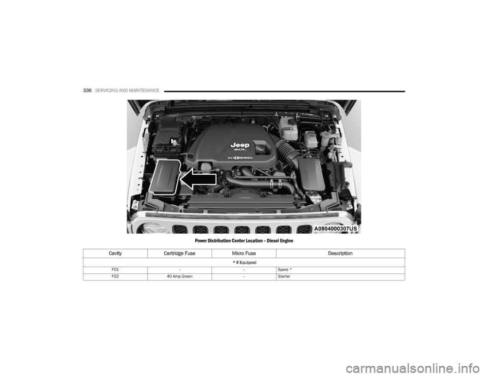
Power Distribution Center Location – Diesel Engine
Cavity Cartridge Fuse Micro Fuse Description
* If Equipped
F01 ––Spare *
F02 40 Amp Green –Starter
23_JL_OM_EN_USC_t.book Page 336
Page 339 of 396
SERVICING AND MAINTENANCE337
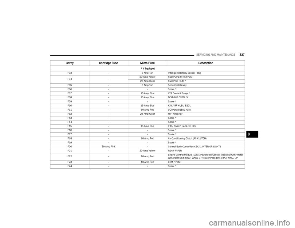
F03 –5 Amp TanIntelligent Battery Sensor (IBS)
F04 –20 Amp Yellow Fuel Pump MTR/FPCM
25 Amp Clear Fuel Pmp (6.4) *
F05 –5 Amp TanSecurity Gateway
F06 ––Spare *
F07 –15 Amp BlueLTR Coolant Pump *
F08 –15 Amp BlueTCM-8HP CYGNUS
F09 ––Spare *
F10 –15 Amp BlueKIN / RF HUB / ESCL
F11 –10 Amp RedUCI Port (USB & AUX)
F12 –25 Amp ClearHIFI Amplifier
F13 ––Spare *
F14 ––Spare *
F15 –15 Amp BlueIPC / Switch Bank-HD Elec
F16 ––Spare *
F17 ––Spare *
F18 –10 Amp RedAir Conditioning Clutch (AC CLUTCH)
F19 ––Spare *
F20 30 Amp Pink –Central Body Controller (CBC) 1-INTERIOR LIGHTS
F21 –20 Amp Yellow REAR WIPER
F22 –10 Amp RedEngine Control Module (ECM)/Powertrain Control Module (PCM)/Motor
Generator Unit (MGU) WAKE UP/Power Pack Unit (PPU) WAKE UP
F23 –10 Amp RedECM / PCM
F24 ––Spare *
Cavity Cartridge Fuse Micro Fuse Description
* If Equipped
8
23_JL_OM_EN_USC_t.book Page 337
Page 340 of 396
338SERVICING AND MAINTENANCE
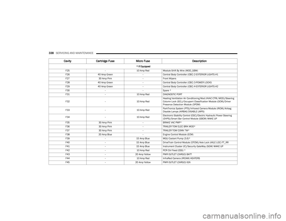
F25 –10 Amp RedModule Shift By Wire (MOD_SBW)
F26 40 Amp Green –Central Body Controller (CBC) 2-EXTERIOR LIGHTS #1
F27 30 Amp Pink –Front Wipers
F28 40 Amp Green –Central Body Controller (CBC) 3-POWER LOCKS
F29 40 Amp Green –Central Body Controller (CBC) 4-EXTERIOR LIGHTS #2
F30 ––Spare *
F31 –10 Amp RedDIAGNOSTIC PORT
F32 –10 Amp RedHeating Ventilation Air Conditioning Mod (HVAC CTRL MOD)/Steering
Column Lock (SCL)/Occupant Classification Module (OCM)/Driver
Presence Detection Module (DPDM)
F33 –10 Amp RedParkTronics System (PTS)/Infrared Camera Module (IRCM)/Airbag
Disable Lamps (AIRBAG DISABLE LMPS)
F34 –10 Amp RedElectronic Stability Control (ESC)/Electric Hydraulic Power Steering
(EHPS)/Smart Bar Control Module (SBCM) WAKE UP
F35 30 Amp Pink –BRAKE VAC PMP*
F36 30 Amp Pink –TRAILER TOW ELEC BRK MOD*
F37 30 Amp Pink –TRAILER TOW CONN 7W*
F38 20 Amp Blue –Engine Control Module (ECM)
F39 –15 Amp BlueMGU Coolant Pump (3.6)*
F40 –15 Amp BlueDriveTrain Control Module (DTCM)/Axle Lock (AXLE LOC) FT_RR
F41 –15 Amp BlueInstrument Cluster (IC)/Security GateWay (SGW) WAKE UP
F42 –10 Amp RedPCR Ctrl Feed (ESS) *
F43 –20 Amp Yellow PWR OUTLET (CARGO) BATT
F44 –10 Amp RedInfraRed Camera (IRCAM) HEATERS
F45 –20 Amp Yellow PWR OUTLET (CARGO) IGN
CavityCartridge Fuse Micro Fuse Description
* If Equipped
23_JL_OM_EN_USC_t.book Page 338
Page 341 of 396
SERVICING AND MAINTENANCE339
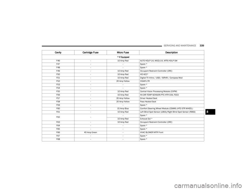
F46 –10 Amp RedAUTO HDLP LVL MOD/LVL MTR/HDLP SW
F47 ––Spare *
F48 ––Spare *
F49 –10 Amp RedOccupant Restraint Controller (ORC)
F50 –10 Amp RedHD ACC*
F51 –10 Amp RedDigital TV Inline / USB / ISRVM / Compass Mod
F52 –20 Amp Yellow CIGAR LTR
F53 ––Spare *
F54 ––Spare *
F55 –10 Amp RedCentral Vision Processing Module (CVPM)
F56 –10 Amp RedIN-CAR TEMP SENSOR/PTC HTR COIL FEED
F57 –20 Amp Yellow Driver Heated Seat
F58 –20 Amp Yellow Pass Heated Seat
F59 ––Spare *
F60 –15 Amp BlueComfort Steering Wheel Module (CSWM) (HTD STR WHEEL)
F61 –10 Amp RedLeft Blind Spot Sensor (LBSS)/Right Blind Spot Sensor (RBSS)
F62 ––
Spare *
10 Amp Red Exhaust Sol *
F63 –10 Amp RedOccupant Restraint Controller (ORC)
F64 ––Spare *
F65 ––Spare *
F66 40 Amp Green –HVAC BLOWER MTR Front
F67 ––Spare *
F68 ––Spare *
Cavity Cartridge Fuse Micro Fuse Description
* If Equipped
8
23_JL_OM_EN_USC_t.book Page 339
Page 342 of 396
340SERVICING AND MAINTENANCE
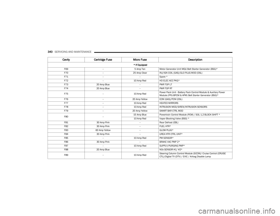
F69 –5 Amp TanMotor Generator Unit MGU Belt Starter Generator (BSG)*
F70 –25 Amp ClearINJ/IGN COIL (GAS)/GLO PLUG MOD (DSL)
F71 ––Spare *
F72 –10 Amp RedHD ELEC ACC PKG*
F73 20 Amp Blue –PWR TOP LT
F74 20 Amp Blue –PWR TOP RT
F75 –10 Amp RedPower Pack Unit - Battery Pack Control Module & Auxiliary Power
Module (PPU-BPCM & APM) Belt Starter Generator (BSG)*
F76 –20 Amp Yellow ECM (GAS)/PCM (DSL)
F77 –10 Amp RedHEATED MIRRORS
F78 –10 Amp RedINTRUSION MOD/SIREN/INTRUSION SENSORS
F79 –20 Amp Yellow SMART BAR CTRL MOD
F80 –15 Amp Blue
Powertrain Control Module (PCM) / SOL 1,2 BLOCK SHIFT *
10 Amp Red Vapor Blocking Valve (BSG) *
F81 30 Amp Pink –Rear Defrost (EBL)
F82 30 Amp Pink –FUEL HTR*
F83 60 Amp Yellow –GLOW PLUG*
F84 30 Amp Pink –UREA HTR CTRL UNIT*
F85 –10 Amp RedPM SENSOR*
F86 30 Amp Pink –BRAKE VAC PMP 2*
F87 –10 Amp RedSUPPLY/PURGING PMP*
F88 20 Amp Blue –NOx SENSOR #1/ #2*
F89 –10 Amp RedSteering Column Control Module (SCCM)/ Cruise Control (CRUISE
CTL)/Digital TV (DTV) / EVIC / Airbag Disable Lamp
Cavity
Cartridge Fuse Micro Fuse Description
* If Equipped
23_JL_OM_EN_USC_t.book Page 340
Page 343 of 396
SERVICING AND MAINTENANCE341
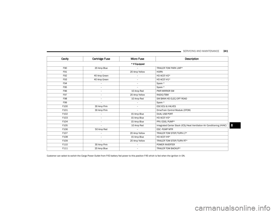
Customer can select to switch the Cargo Power Outlet from F43 battery fed power to this position F45 which is fed when the ignition in ON.F90
20 Amp Blue –TRAILER TOW PARK LMP*
F91 –20 Amp Yellow HORN
F92 40 Amp Green –HD ACCY #2*
F93 40 Amp Green –HD ACCY #1*
F94 ––Spare *
F95 ––Spare *
F96 –10 Amp RedPWR MIRROR SW
F97 –20 Amp Yellow RADIO/TBM
F98 –10 Amp RedSW BANK-HD ELEC/OFF ROAD
F99 ––Spare *
F100 30 Amp Pink –ESC-ECU & VALVES
F101 30 Amp Pink –DriveTrain Control Module (DTCM)
F102 –15 Amp BlueDUAL USB PORT
F103 –15 Amp BlueHD ACCY #3*
F104 –15 Amp BluePPU COOL PUMP*
F105 –10 Amp RedIntegrated Center Stack (ICS)/Heat Ventilation Air Conditioning (HVAC)
F106 50 Amp Red –ESC -PUMP MTR
F107 –20 Amp Yellow TRAILER TOW STOP/TURN LT*
F108 –15 Amp BlueHD ACCY #4*
F109 –20 Amp Yellow TRAILER TOW STOP/TURN RT*
F110 30 Amp Pink –POWER INVERTER
F111 20 Amp Blue –TRAILER TOW BACKUP*
Cavity Cartridge Fuse Micro Fuse Description
* If Equipped
8
23_JL_OM_EN_USC_t.book Page 341
Page 344 of 396
342SERVICING AND MAINTENANCE
BULB REPLACEMENT
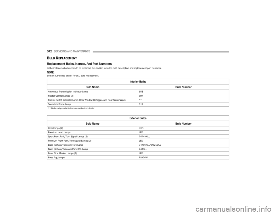
Replacement Bulbs, Names, And Part Numbers
In the instance a bulb needs to be replaced, this section includes bulb description and replacement part numbers.
NOTE:See an authorized dealer for LED bulb replacement.
Interior Bulbs
Bulb Name Bulb Number
Automatic Transmission Indicator Lamp 658
Heater Control Lamps (2) 194
Rocker Switch Indicator Lamp (Rear Window Defogger, and Rear Wash/Wipe) **
Soundbar Dome Lamp 912
** Bulbs only available from an authorized dealer.
Exterior Bulbs
Bulb Name Bulb Number
Headlamps (2) H13
Premium Head Lamps LED
Sport Front Park/Turn Signal Lamps (2) 7444NALL
Premium Front Park/Turn Signal Lamps (2) LED
Base (Sahara/Rubicon) Turn Lamp 7440NALL/WY21WLL
Base (Sahara/Rubicon) Park DRL Lamp 7443LL
Front Side Marker Lamps (2) LED
Base Fog Lamps PSX24W
23_JL_OM_EN_USC_t.book Page 342
Page 347 of 396
SERVICING AND MAINTENANCE345
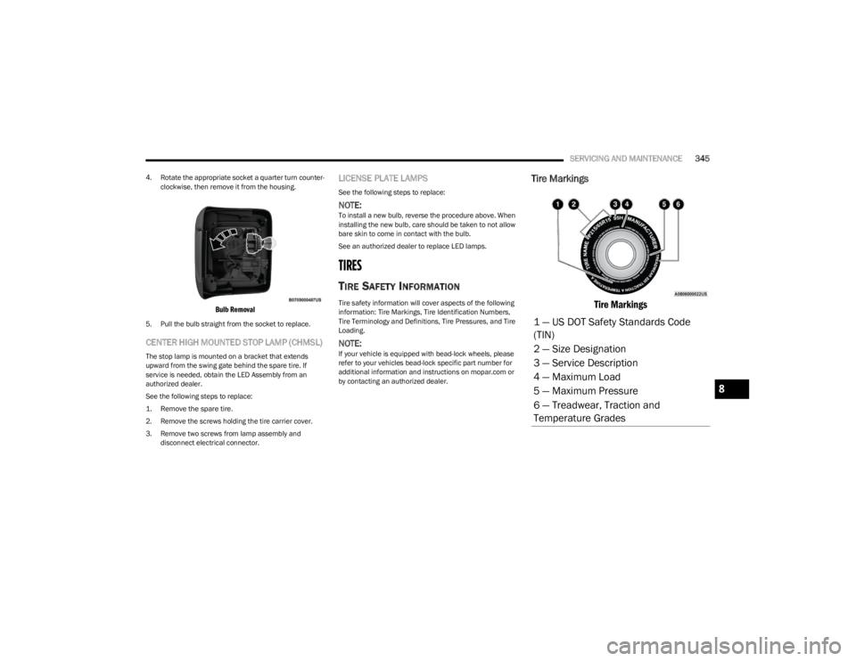
4. Rotate the appropriate socket a quarter turn counter -
clockwise, then remove it from the housing.
Bulb Removal
5. Pull the bulb straight from the socket to replace.
CENTER HIGH MOUNTED STOP LAMP (CHMSL)
The stop lamp is mounted on a bracket that extends
upward from the swing gate behind the spare tire. If
service is needed, obtain the LED Assembly from an
authorized dealer.
See the following steps to replace:
1. Remove the spare tire.
2. Remove the screws holding the tire carrier cover.
3. Remove two screws from lamp assembly and disconnect electrical connector.
LICENSE PLATE LAMPS
See the following steps to replace:
NOTE:To install a new bulb, reverse the procedure above. When
installing the new bulb, care should be taken to not allow
bare skin to come in contact with the bulb.
See an authorized dealer to replace LED lamps.
TIRES
TIRE SAFETY INFORMATION
Tire safety information will cover aspects of the following
information: Tire Markings, Tire Identification Numbers,
Tire Terminology and Definitions, Tire Pressures, and Tire
Loading.
NOTE:If your vehicle is equipped with bead-lock wheels, please
refer to your vehicles bead-lock specific part number for
additional information and instructions on mopar.com or
by contacting an authorized dealer.
Tire Markings
Tire Markings
1 — US DOT Safety Standards Code
(TIN)
2 — Size Designation
3 — Service Description
4 — Maximum Load
5 — Maximum Pressure
6 — Treadwear, Traction and
Temperature Grades
8
23_JL_OM_EN_USC_t.book Page 345
Page 349 of 396
SERVICING AND MAINTENANCE347
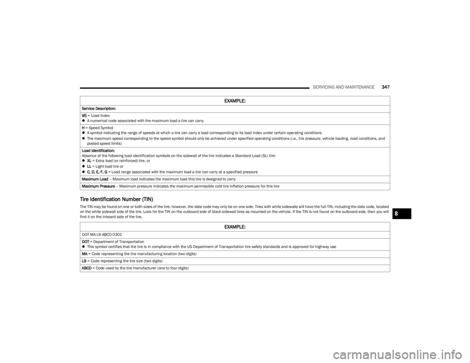
Tire Identification Number (TIN)
The TIN may be found on one or both sides of the tire; however, the date code may only be on one side. Tires with white sidewalls will have the full TIN, including the date code, located
on the white sidewall side of the tire. Look for the TIN on the outboard side of black sidewall tires as mounted on the vehicle. If the TIN is not found on the outboard side, then you will
find it on the inboard side of the tire.Service Description:
95
= Load Index
A numerical code associated with the maximum load a tire can carry
H = Speed Symbol
A symbol indicating the range of speeds at which a tire can carry a load corresponding to its load index under certain operating conditions
The maximum speed corresponding to the speed symbol should only be achieved under specified operating conditions (i.e., tire pressure, vehicle loading, road conditions, and
posted speed limits)
Load Identification:
Absence of the following load identification symbols on the sidewall of the tire indicates a Standard Load (SL) tire:
XL = Extra load (or reinforced) tire, or
LL = Light load tire or
C, D, E, F, G = Load range associated with the maximum load a tire can carry at a specified pressure
Maximum Load – Maximum load indicates the maximum load this tire is designed to carry
Maximum Pressure – Maximum pressure indicates the maximum permissible cold tire inflation pressure for this tire
EXAMPLE:
EXAMPLE:
DOT MA L9 ABCD 0301
DOT = Department of Transportation
This symbol certifies that the tire is in compliance with the US Department of Transportation tire safety standards and is approved for highway use
MA = Code representing the tire manufacturing location (two digits)
L9 = Code representing the tire size (two digits)
ABCD = Code used by the tire manufacturer (one to four digits)
8
23_JL_OM_EN_USC_t.book Page 347