ignition JEEP WRANGLER 2DOORS 2018 Owner handbook (in English)
[x] Cancel search | Manufacturer: JEEP, Model Year: 2018, Model line: WRANGLER 2DOORS, Model: JEEP WRANGLER 2DOORS 2018Pages: 348, PDF Size: 6.5 MB
Page 172 of 348
ment Panel” for further information, fill the
AdBlue (UREA) tank with no more than
2 Gallons (8 liters).
• If containers which can be screwed to the
filler are used, the reservoir is full when the
AdBlue (UREA) level in the container stops
pouring out. Do not proceed further.
Operations After Refilling
Proceed as follows:
• Fit the cap back on the AdBlue (UREA)
filler by turning it clockwise and screwing it
completely.
• Cycle the ignition to RUN (it is not neces-
sary to start the engine).
• Wait for the indication on the instrument
panel to switch off before moving the car.
The indication may stay on for a few sec-
onds to approximately half a minute. If the
engine is started and the car is moved, the
indication will remain on for longer. This
will not compromise engine operation.• If the AdBlue (UREA) was topped up when
the tank was empty, wait for 2 minutes
before starting the engine.
NOTE:
• If AdBlue (UREA) is spilled out of the filler
neck, clean up well the area and proceed to
filling up again. If the liquid crystallizes,
eliminate it with a sponge and warm water.
• DO NOT EXCEED THE MAXIMUM LEVEL:
this could cause damage to the reservoir.
AdBlue (UREA) freezes at under 12° F
(-11° C). Although the system is designed
to operate below the freezing point of the
UREA, it is advisable not to fill the tank
beyond the maximum level because if the
UREA freezes the system can be damaged.
Follow the instructions in this section.
• If the AdBlue (UREA) is spilled on painted
surfaces or aluminium, immediately clean
the area with water and use absorbent ma-
terial to collect the fluid that has been
spilled on the ground.• Do not try to start the engine if AdBlue
(UREA) was accidentally added to the die-
sel fuel tank, this can result in serious
engine damage, contact an authorized
dealer.
• Do not add additives or other fluids to
AdBlue (UREA), doing so could damage the
system.
• The use of non-conforming or degraded
AdBlue (UREA) may lead to indications
appearing on the instrument panel display
refer to “Warning Lights And Messages" in
the “Getting To Know Your Instrument
Panel” for further information.
• Never pour AdBlue (UREA) into another
container: it could be contaminated.
• If the AdBlue (UREA) runs out, see refer to
“Warning Lights And Messages" in the
“Getting To Know Your Instrument Panel”
for further information to continue using
the car normally.
STARTING AND OPERATING
170
Page 178 of 348
HAZARD WARNING
FLASHERS
The Hazard Warning flasher switch is located
on the instrument panel below the climate
controls.
Push the switch to turn on the
Hazard Warning flasher. When the
switch is activated, all directionalturn signals will flash on and off to warn
oncoming traffic of an emergency. Push the
switch a second time to turn off the Hazard
Warning flashers.
This is an emergency warning system and it
should not be used when the vehicle is in
motion. Use it when your vehicle is disabled
and it is creating a safety hazard for other
motorists.When you must leave the vehicle to seek
assistance, the Hazard Warning flashers will
continue to operate even though the ignition
is placed in the OFF position.
NOTE:
With extended use the Hazard Warning flash-
ers may wear down your battery.
BULB REPLACEMENT
Replacement Bulbs
Interior Bulbs
Bulb Number
Automatic Transmission Indicator Lamp 658
Heater Control Lamps (2)194
Rocker Switch Indicator Lamp (Rear Window Defogger, and Rear Wash/
Wipe)**
Soundbar Dome Lamp912
** Bulbs only available from an authorized dealer.
IN CASE OF EMERGENCY
176
Page 182 of 348
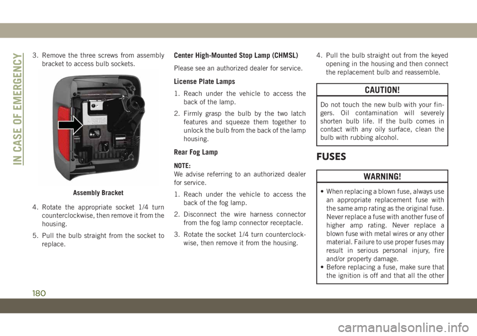
3. Remove the three screws from assembly
bracket to access bulb sockets.
4. Rotate the appropriate socket 1/4 turn
counterclockwise, then remove it from the
housing.
5. Pull the bulb straight from the socket to
replace.Center High-Mounted Stop Lamp (CHMSL)
Please see an authorized dealer for service.
License Plate Lamps
1. Reach under the vehicle to access the
back of the lamp.
2. Firmly grasp the bulb by the two latch
features and squeeze them together to
unlock the bulb from the back of the lamp
housing.
Rear Fog Lamp
NOTE:
We advise referring to an authorized dealer
for service.
1. Reach under the vehicle to access the
back of the fog lamp.
2. Disconnect the wire harness connector
from the fog lamp connector receptacle.
3. Rotate the socket 1/4 turn counterclock-
wise, then remove it from the housing.4. Pull the bulb straight out from the keyed
opening in the housing and then connect
the replacement bulb and reassemble.
CAUTION!
Do not touch the new bulb with your fin-
gers. Oil contamination will severely
shorten bulb life. If the bulb comes in
contact with any oily surface, clean the
bulb with rubbing alcohol.
FUSES
WARNING!
• When replacing a blown fuse, always use
an appropriate replacement fuse with
the same amp rating as the original fuse.
Never replace a fuse with another fuse of
higher amp rating. Never replace a
blown fuse with metal wires or any other
material. Failure to use proper fuses may
result in serious personal injury, fire
and/or property damage.
• Before replacing a fuse, make sure that
the ignition is off and that all the otherAssembly Bracket
IN CASE OF EMERGENCY
180
Page 184 of 348
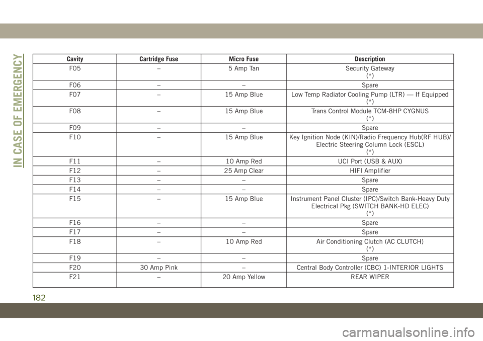
Cavity Cartridge Fuse Micro Fuse Description
F05 – 5 Amp Tan Security Gateway
(*)
F06 – – Spare
F07 – 15 Amp Blue Low Temp Radiator Cooling Pump (LTR) — If Equipped
(*)
F08 – 15 Amp Blue Trans Control Module TCM-8HP CYGNUS
(*)
F09 – – Spare
F10 – 15 Amp Blue Key Ignition Node (KIN)/Radio Frequency Hub(RF HUB)/
Electric Steering Column Lock (ESCL)
(*)
F11 – 10 Amp Red UCI Port (USB & AUX)
F12 – 25 Amp Clear HIFI Amplifier
F13 – – Spare
F14 – – Spare
F15 – 15 Amp Blue Instrument Panel Cluster (IPC)/Switch Bank-Heavy Duty
Electrical Pkg (SWITCH BANK-HD ELEC)
(*)
F16 – – Spare
F17 – – Spare
F18 – 10 Amp Red Air Conditioning Clutch (AC CLUTCH)
(*)
F19 – – Spare
F20 30 Amp Pink – Central Body Controller (CBC) 1-INTERIOR LIGHTS
F21 – 20 Amp Yellow REAR WIPER
IN CASE OF EMERGENCY
182
Page 193 of 348
3. Reinstall the tire cover if applicable.
NOTE:
If you have added aftermarket accessories to
the spare tire mounted carrier, it cannot ex-
ceed a gross weight of 85 lbs (38.5 kg)
including the weight of the spare tire.
Preparations For Jacking
1. Park on a firm, level surface. Avoid ice or
slippery areas.
WARNING!
Do not attempt to change a tire on the side
of the vehicle close to moving traffic. Pull
far enough off the road to avoid being hit
when operating the jack or changing the
wheel.
2. Turn on the Hazard Warning flasher.
3. Apply the parking brake.
4. Shift the automatic transmission into
PARK.
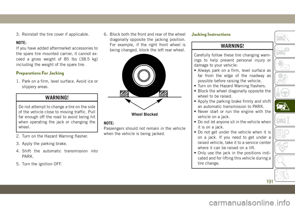
5. Turn the ignition OFF.6. Block both the front and rear of the wheel
diagonally opposite the jacking position.
For example, if the right front wheel is
being changed, block the left rear wheel.
NOTE:
Passengers should not remain in the vehicle
when the vehicle is being jacked.
Jacking Instructions
WARNING!
Carefully follow these tire changing warn-
ings to help prevent personal injury or
damage to your vehicle:
• Always park on a firm, level surface as
far from the edge of the roadway as
possible before raising the vehicle.
• Turn on the Hazard Warning flashers.
• Block the wheel diagonally opposite the
wheel to be raised.
• Apply the parking brake firmly and shift
an automatic transmission to PARK.
• Never start or run the engine with the
vehicle on a jack.
• Do not let anyone sit in the vehicle when
it is on a jack.
• Do not get under the vehicle when it is
on a jack. If you need to get under a
raised vehicle, take it to a service center
where it can be raised on a lift.
• Only use the jack in the positions indi-
cated and for lifting this vehicle during a
tire change.
Wheel Blocked
191
Page 199 of 348
CAUTION!
Do not use a portable battery booster pack
or any other booster source with a system
voltage greater than 12 Volts or damage to
the battery, starter motor, alternator or
electrical system may occur.
NOTE:
When using a portable battery booster pack,
follow the manufacturer's operating instruc-
tions and precautions.
Preparations For Jump Start
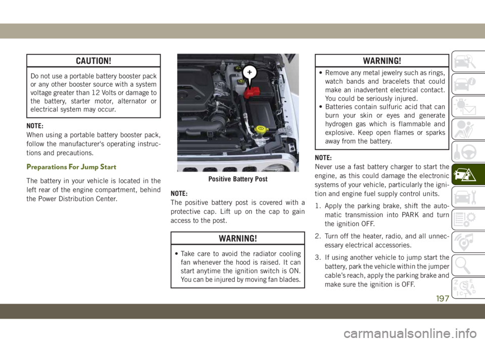
The battery in your vehicle is located in the
left rear of the engine compartment, behind
the Power Distribution Center.NOTE:
The positive battery post is covered with a
protective cap. Lift up on the cap to gain
access to the post.
WARNING!
• Take care to avoid the radiator cooling
fan whenever the hood is raised. It can
start anytime the ignition switch is ON.
You can be injured by moving fan blades.
WARNING!
• Remove any metal jewelry such as rings,
watch bands and bracelets that could
make an inadvertent electrical contact.
You could be seriously injured.
• Batteries contain sulfuric acid that can
burn your skin or eyes and generate
hydrogen gas which is flammable and
explosive. Keep open flames or sparks
away from the battery.
NOTE:
Never use a fast battery charger to start the
engine, as this could damage the electronic
systems of your vehicle, particularly the igni-
tion and engine fuel supply control units.
1. Apply the parking brake, shift the auto-
matic transmission into PARK and turn
the ignition OFF.
2. Turn off the heater, radio, and all unnec-
essary electrical accessories.
3. If using another vehicle to jump start the
battery, park the vehicle within the jumper
cable’s reach, apply the parking brake and
make sure the ignition is OFF.
Positive Battery Post
197
Page 204 of 348
TOWING A DISABLED
VEHICLE
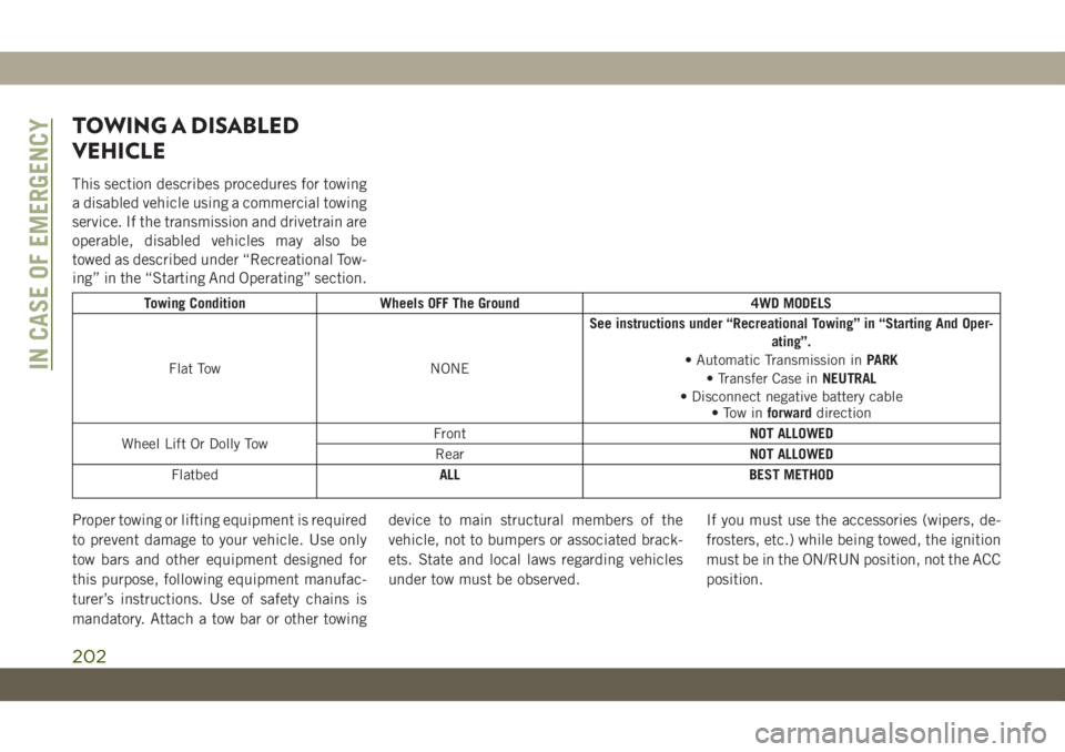
This section describes procedures for towing
a disabled vehicle using a commercial towing
service. If the transmission and drivetrain are
operable, disabled vehicles may also be
towed as described under “Recreational Tow-
ing” in the “Starting And Operating” section.
Towing Condition Wheels OFF The Ground 4WD MODELS
Flat Tow NONESee instructions under “Recreational Towing” in “Starting And Oper-
ating”.
• Automatic Transmission inPARK
• Transfer Case inNEUTRAL
• Disconnect negative battery cable
• Tow inforwarddirection
Wheel Lift Or Dolly TowFrontNOT ALLOWED
RearNOT ALLOWED
FlatbedALL BEST METHOD
Proper towing or lifting equipment is required
to prevent damage to your vehicle. Use only
tow bars and other equipment designed for
this purpose, following equipment manufac-
turer’s instructions. Use of safety chains is
mandatory. Attach a tow bar or other towingdevice to main structural members of the
vehicle, not to bumpers or associated brack-
ets. State and local laws regarding vehicles
under tow must be observed.If you must use the accessories (wipers, de-
frosters, etc.) while being towed, the ignition
must be in the ON/RUN position, not the ACC
position.
IN CASE OF EMERGENCY
202
Page 205 of 348
If the vehicle's battery is discharged, refer to
"Manual Park Release" in this section for
instructions on shifting the automatic trans-
mission out of PARK in order to move the
vehicle.
CAUTION!
• Do not use sling type equipment when
towing. Vehicle damage may occur.
• When securing the vehicle to a flatbed
truck, do not attach to front or rear
suspension components. Damage to
your vehicle may result from improper
towing.
• If the vehicle being towed requires steer-
ing, the ignition switch must be in the
ACC or ON/RUN mode, not in the OFF
mode.
Without The Key Fob
Special care must be taken when the vehicle
is towed with the ignition in the OFF mode.
The only approved method of towing without
the key fob is with a flatbed truck. Proper
towing equipment is necessary to prevent
damage to the vehicle.
Four–Wheel Drive Models
The manufacturer recommends towing with
all wheelsOFFthe ground. Acceptable meth-
ods are to tow the vehicle on a flatbed or with
one end of the vehicle raised and the opposite
end on a towing dolly.
If flatbed equipment is not available and the
transfer case is operable, the vehicle may be
towed (in the forward direction, withALL
wheels on the ground),IFthe transfer case is
inNEUTRAL(N) and the transmission is in
PARK. Refer to “Recreational Towing” in
“Starting And Operating” for detailed
instructions.
CAUTION!
• Front or rear wheel lifts must not be used
(if the remaining wheels are on the
ground). Internal damage to the trans-
mission or transfer case will occur if a
front or rear wheel lift is used when
towing.
• Towing this vehicle in violation of the
above requirements can cause severe
transmission and/or transfer case dam-
CAUTION!
age. Damage from improper towing is
not covered under the New Vehicle Lim-
ited Warranty.
Tow Eye Usage
Your vehicle is equipped with a tow eye that
can be used to move a disabled vehicle.
When using a tow eye be sure to follow the
“Tow Eye Usage Precautions” and the “Tow-
ing A Disabled Vehicle” instructions in this
section.
The tow eyes are mounted below the front and
rear bumpers.
Tow Eye Usage Precautions
WARNING!
Stand clear of vehicles when pulling with
tow eyes.
• Do not use a chain with a tow eye.
Chains may break, causing serious injury
or death.
203
Page 226 of 348
Installing The Rear Wiper
1. Lift the wiper arm off of the glass.
2. Insert the wiper blade pivot pin into the
opening on the end of the wiper arm and
rotate the wiper in to place.
3. Place with wiper on the glass and close
the tail gate.
Cooling System
WARNING!
• You or others can be badly burned by hot
engine coolant (antifreeze) or steam
from your radiator. If you see or hear
steam coming from under the hood, do
not open the hood until the radiator has
had time to cool. Never open a cooling
system pressure cap when the radiator
or coolant bottle is hot.
• Keep hands, tools, clothing, and jewelry
away from the radiator cooling fan when
the hood is raised. The fan starts auto-
matically and may start at any time,
whether the engine is running or not.
WARNING!
• When working near the radiator cooling
fan, turn the ignition to the OFF mode.
The fan is temperature controlled and
can start at any time the ignition is in the
ON mode.
Coolant Checks
Check the engine and, intercooler (if
equipped) coolant (antifreeze) protection ev-
ery 12 months (before the onset of freezing
weather, where applicable). If the engine
and, intercooler (if equipped) is dirty or rusty
in appearance, the system should be drained,
flushed and refilled with fresh OAT coolant
(conforming to MS.90032) by an authorized
dealer. Check the front of the A/C condenser
(if equipped) or radiator for any accumulation
of bugs, leaves, etc. If dirty, clean by gently
spraying water from a garden hose vertically
down the face of the A/C condenser (if
equipped) or the back of the radiator core.
Check the engine and, intercooler (if
equipped) cooling system hoses for brittle
rubber, cracking, tears, cuts, and tightness ofthe connection at the coolant recovery bottle
and radiator. Inspect the entire system for
leaks. DO NOT REMOVE THE COOLANT
PRESSURE CAP WHEN THE COOLING SYS-
TEM IS HOT.
Brake System
In order to assure brake system performance,
all brake system components should be in-
spected periodically. Refer to the “Mainte-
nance Plan” in this section for the proper
maintenance intervals.
WARNING!
Riding the brakes can lead to brake failure
and possibly a collision. Driving with your
foot resting or riding on the brake pedal
can result in abnormally high brake tem-
peratures, excessive lining wear, and pos-
sible brake damage. You would not have
your full braking capacity in an emergency.
Fluid Level Check — Brake Master Cylinder
The fluid level of the master cylinder should
be checked whenever the vehicle is serviced,
or immediately if the brake system warning
SERVICING AND MAINTENANCE
224
Page 275 of 348
• Press the “+” or “–” buttons on the touch-
screen, or press and drag over the level bar
for each of the equalizer bands. The level
value, which spans between plus or minus
nine, is displayed at the bottom of each of
the bands.
Speed Adjusted Volume
• Press the “Speed Adjusted Volume” button
on the touchscreen to activate the Speed
Adjusted Volume screen. The Speed Ad-
justed Volume is adjusted by pressing the
volume level indicator. This alters the auto-
matic adjustment of the audio volume with
variation to vehicle speed.
Loudness — If Equipped
• Press the “On” button on the touchscreen
to activate Loudness. Press “Off” to deac-
tivate this feature. When Loudness is On,
the sound quality at lower volumes
improves.
AUX Volume Offset
• Press the “AUX Volume Offset” button on
the touchscreen to activate the AUX Vol-
ume Offset screen. The AUX Volume Offset
is adjusted by pressing of the “+” and “–”buttons. This alters the AUX input audio
volume. The level value, which spans be-
tween plus or minus three, is displayed
above the adjustment bar.
Auto Play — If Equipped
• Press the “Auto Play” button on the touch-
screen to activate the Auto Play screen. The
Auto Play feature has two settings “On” and
“Off.” With Auto Play on, music begins
playing from a connected device, immedi-
ately after it is connected to the radio.
Auto On Radio — If Equipped
• The Radio automatically turns on when
vehicle is in run or will recall whether it was
on or off at last ignition off.
Radio Off With Door — If Equipped
• Press the “Radio Off With Door” button on
the touchscreen to activate the Radio Off
With Door screen. The Radio Off With Door
feature, when activated, keeps the radio on
until the driver or passenger door is opened,
or when the Radio Off Delay selected time
has expired.Drag & Drop Menu Bar
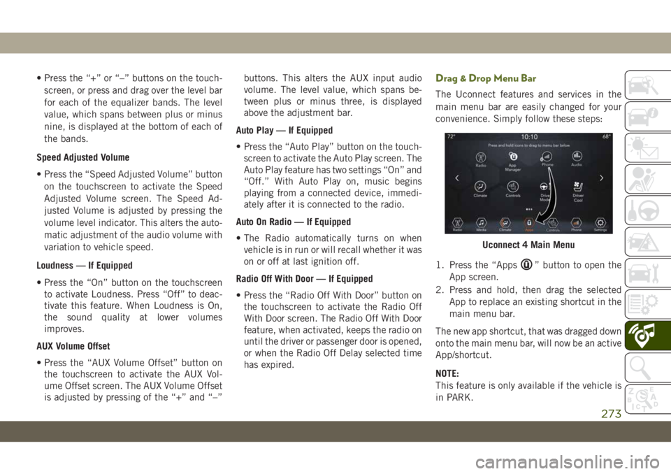
The Uconnect features and services in the
main menu bar are easily changed for your
convenience. Simply follow these steps:
1. Press the “Apps
” button to open the
App screen.
2. Press and hold, then drag the selected
App to replace an existing shortcut in the
main menu bar.
The new app shortcut, that was dragged down
onto the main menu bar, will now be an active
App/shortcut.
NOTE:
This feature is only available if the vehicle is
in PARK.
Uconnect 4 Main Menu
273