JEEP XJ 1995 Service And Repair Manual
Manufacturer: JEEP, Model Year: 1995, Model line: XJ, Model: JEEP XJ 1995Pages: 2158, PDF Size: 81.9 MB
Page 1621 of 2158
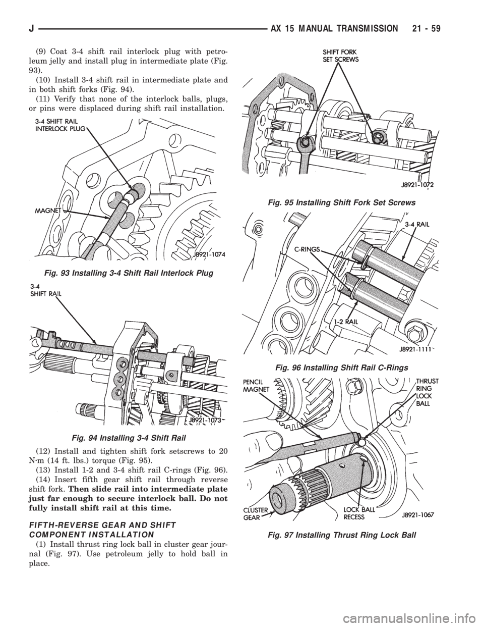
(9) Coat 3-4 shift rail interlock plug with petro-
leum jelly and install plug in intermediate plate (Fig.
93).
(10) Install 3-4 shift rail in intermediate plate and
in both shift forks (Fig. 94).
(11) Verify that none of the interlock balls, plugs,
or pins were displaced during shift rail installation.
(12) Install and tighten shift fork setscrews to 20
Nzm (14 ft. lbs.) torque (Fig. 95).
(13) Install 1-2 and 3-4 shift rail C-rings (Fig. 96).
(14) Insert fifth gear shift rail through reverse
shift fork.Then slide rail into intermediate plate
just far enough to secure interlock ball. Do not
fully install shift rail at this time.
FIFTH-REVERSE GEAR AND SHIFT
COMPONENT INSTALLATION
(1) Install thrust ring lock ball in cluster gear jour-
nal (Fig. 97). Use petroleum jelly to hold ball in
place.
Fig. 93 Installing 3-4 Shift Rail Interlock Plug
Fig. 94 Installing 3-4 Shift Rail
Fig. 95 Installing Shift Fork Set Screws
Fig. 96 Installing Shift Rail C-Rings
Fig. 97 Installing Thrust Ring Lock Ball
JAX 15 MANUAL TRANSMISSION 21 - 59
Page 1622 of 2158
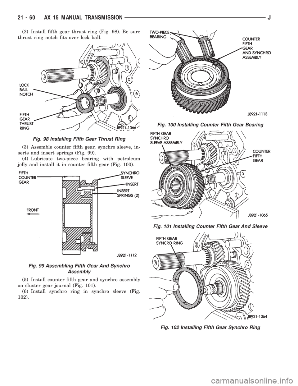
(2) Install fifth gear thrust ring (Fig. 98). Be sure
thrust ring notch fits over lock ball.
(3) Assemble counter fifth gear, synchro sleeve, in-
serts and insert springs (Fig. 99).
(4) Lubricate two-piece bearing with petroleum
jelly and install it in counter fifth gear (Fig. 100).
(5) Install counter fifth gear and synchro assembly
on cluster gear journal (Fig. 101).
(6) Install synchro ring in synchro sleeve (Fig.
102).
Fig. 98 Installing Fifth Gear Thrust Ring
Fig. 99 Assembling Fifth Gear And Synchro
Assembly
Fig. 100 Installing Counter Fifth Gear Bearing
Fig. 101 Installing Counter Fifth Gear And Sleeve
Fig. 102 Installing Fifth Gear Synchro Ring
21 - 60 AX 15 MANUAL TRANSMISSIONJ
Page 1623 of 2158
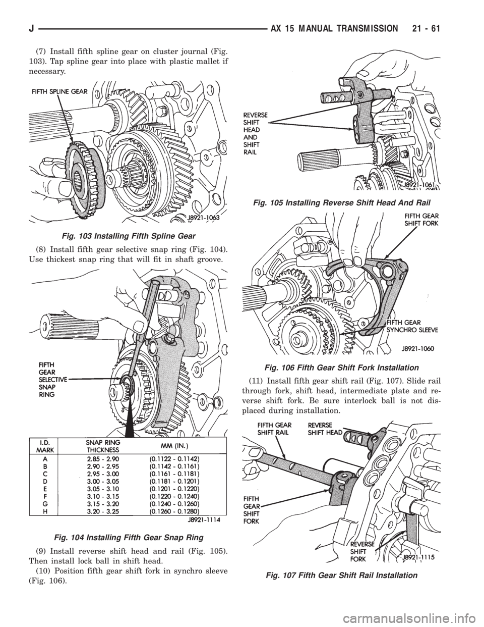
(7) Install fifth spline gear on cluster journal (Fig.
103). Tap spline gear into place with plastic mallet if
necessary.
(8) Install fifth gear selective snap ring (Fig. 104).
Use thickest snap ring that will fit in shaft groove.
(9) Install reverse shift head and rail (Fig. 105).
Then install lock ball in shift head.
(10) Position fifth gear shift fork in synchro sleeve
(Fig. 106).(11) Install fifth gear shift rail (Fig. 107). Slide rail
through fork, shift head, intermediate plate and re-
verse shift fork. Be sure interlock ball is not dis-
placed during installation.
Fig. 103 Installing Fifth Spline Gear
Fig. 104 Installing Fifth Gear Snap Ring
Fig. 105 Installing Reverse Shift Head And Rail
Fig. 106 Fifth Gear Shift Fork Installation
Fig. 107 Fifth Gear Shift Rail Installation
JAX 15 MANUAL TRANSMISSION 21 - 61
Page 1624 of 2158
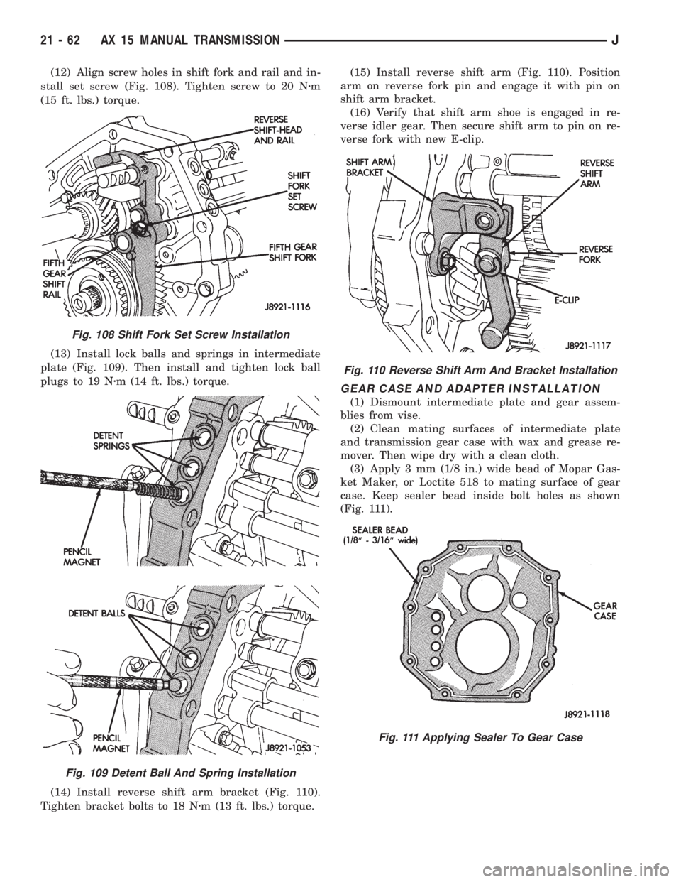
(12) Align screw holes in shift fork and rail and in-
stall set screw (Fig. 108). Tighten screw to 20 Nzm
(15 ft. lbs.) torque.
(13) Install lock balls and springs in intermediate
plate (Fig. 109). Then install and tighten lock ball
plugs to 19 Nzm (14 ft. lbs.) torque.
(14) Install reverse shift arm bracket (Fig. 110).
Tighten bracket bolts to 18 Nzm (13 ft. lbs.) torque.(15) Install reverse shift arm (Fig. 110). Position
arm on reverse fork pin and engage it with pin on
shift arm bracket.
(16) Verify that shift arm shoe is engaged in re-
verse idler gear. Then secure shift arm to pin on re-
verse fork with new E-clip.
GEAR CASE AND ADAPTER INSTALLATION
(1) Dismount intermediate plate and gear assem-
blies from vise.
(2) Clean mating surfaces of intermediate plate
and transmission gear case with wax and grease re-
mover. Then wipe dry with a clean cloth.
(3) Apply 3 mm (1/8 in.) wide bead of Mopar Gas-
ket Maker, or Loctite 518 to mating surface of gear
case. Keep sealer bead inside bolt holes as shown
(Fig. 111).
Fig. 108 Shift Fork Set Screw Installation
Fig. 109 Detent Ball And Spring Installation
Fig. 110 Reverse Shift Arm And Bracket Installation
Fig. 111 Applying Sealer To Gear Case
21 - 62 AX 15 MANUAL TRANSMISSIONJ
Page 1625 of 2158
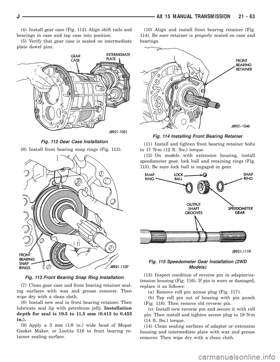
(4) Install gear case (Fig. 112). Align shift rails and
bearings in case and tap case into position.
(5) Verify that gear case is seated on intermediate
plate dowel pins.
(6) Install front bearing snap rings (Fig. 113).
(7) Clean gear case and front bearing retainer seal-
ing surfaces with wax and grease remover. Then
wipe dry with a clean cloth.
(8) Install new seal in front bearing retainer. Then
lubricate seal lip with petroleum jelly.Installation
depth for seal is 10.5 to 11.5 mm (0.413 to 0.453
in.).
(9) Applya3mm(1/8 in.) wide bead of Mopar
Gasket Maker, or Loctite 518 to front bearing re-
tainer sealing surface.(10) Align and install front bearing retainer (Fig.
114). Be sure retainer is properly seated on case and
bearings.
(11) Install and tighten front bearing retainer bolts
to 17 Nzm (12 ft. lbs.) torque.
(12) On models with extension housing, install
speedometer gear, lock ball and retaining rings (Fig.
115). Be sure lock ball is engaged in gear.
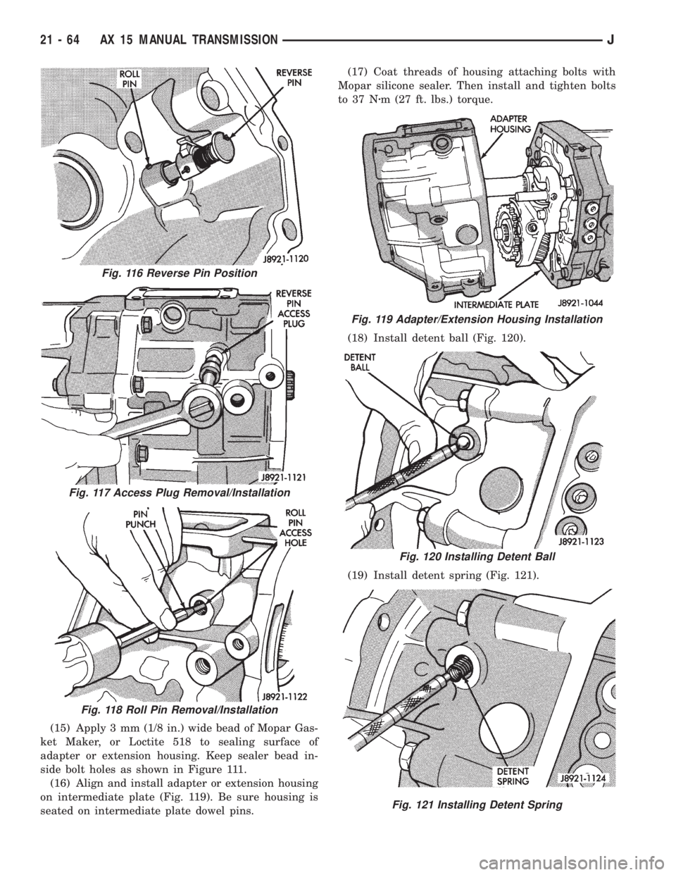
(13) Inspect condition of reverse pin in adapter/ex-
tension housing (Fig. 116). If pin is worn or damaged,
replace it as follows:
(a) Remove roll pin access plug (Fig. 117).
(b) Tap roll pin out of housing with pin punch
(Fig. 118). Then remove old reverse pin.
(c) Install new reverse pin and secure it with roll
pin. Then install and tighten access plug to 19 Nzm
(14 ft. lbs.) torque.
(14) Clean sealing surfaces of adapter or extension
housing and intermediate plate with wax and grease
remover. Then wipe dry with a clean cloth.
Fig. 112 Gear Case Installation
Fig. 113 Front Bearing Snap Ring Installation
Fig. 114 Installing Front Bearing Retainer
Fig. 115 Speedometer Gear Installation (2WD
Models)
JAX 15 MANUAL TRANSMISSION 21 - 63
Page 1626 of 2158
(15) Apply 3 mm (1/8 in.) wide bead of Mopar Gas-
ket Maker, or Loctite 518 to sealing surface of
adapter or extension housing. Keep sealer bead in-
side bolt holes as shown in Figure 111.
(16) Align and install adapter or extension housing
on intermediate plate (Fig. 119). Be sure housing is
seated on intermediate plate dowel pins.(17) Coat threads of housing attaching bolts with
Mopar silicone sealer. Then install and tighten bolts
to 37 Nzm (27 ft. lbs.) torque.
(18) Install detent ball (Fig. 120).
(19) Install detent spring (Fig. 121).
Fig. 116 Reverse Pin Position
Fig. 117 Access Plug Removal/Installation
Fig. 118 Roll Pin Removal/Installation
Fig. 119 Adapter/Extension Housing Installation
Fig. 120 Installing Detent Ball
Fig. 121 Installing Detent Spring
21 - 64 AX 15 MANUAL TRANSMISSIONJ
Page 1627 of 2158
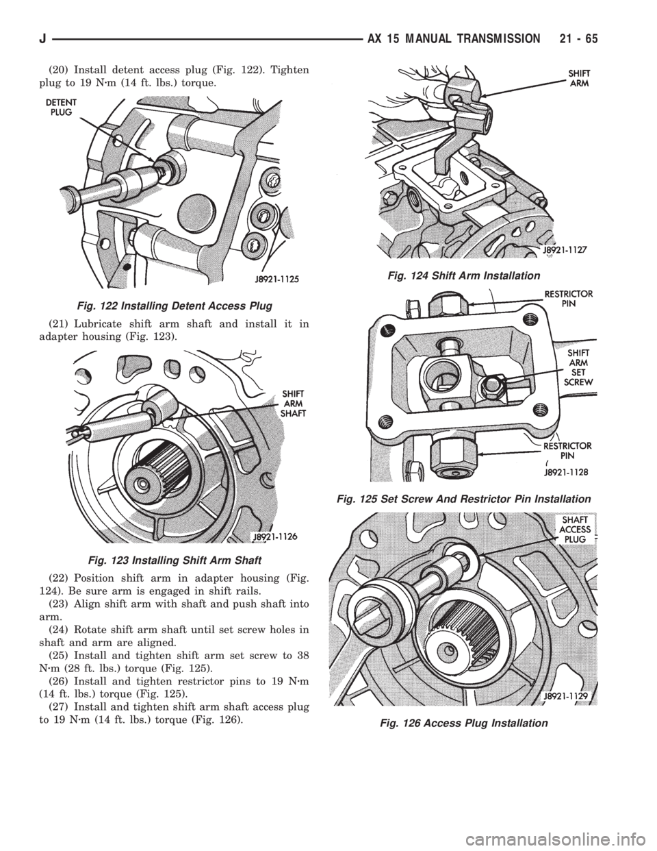
(20) Install detent access plug (Fig. 122). Tighten
plug to 19 Nzm (14 ft. lbs.) torque.
(21) Lubricate shift arm shaft and install it in
adapter housing (Fig. 123).
(22) Position shift arm in adapter housing (Fig.
124). Be sure arm is engaged in shift rails.
(23) Align shift arm with shaft and push shaft into
arm.
(24) Rotate shift arm shaft until set screw holes in
shaft and arm are aligned.
(25) Install and tighten shift arm set screw to 38
Nzm (28 ft. lbs.) torque (Fig. 125).
(26) Install and tighten restrictor pins to 19 Nzm
(14 ft. lbs.) torque (Fig. 125).
(27) Install and tighten shift arm shaft access plug
to 19 Nzm (14 ft. lbs.) torque (Fig. 126).
Fig. 122 Installing Detent Access Plug
Fig. 123 Installing Shift Arm Shaft
Fig. 124 Shift Arm Installation
Fig. 125 Set Screw And Restrictor Pin Installation
Fig. 126 Access Plug Installation
JAX 15 MANUAL TRANSMISSION 21 - 65
Page 1628 of 2158
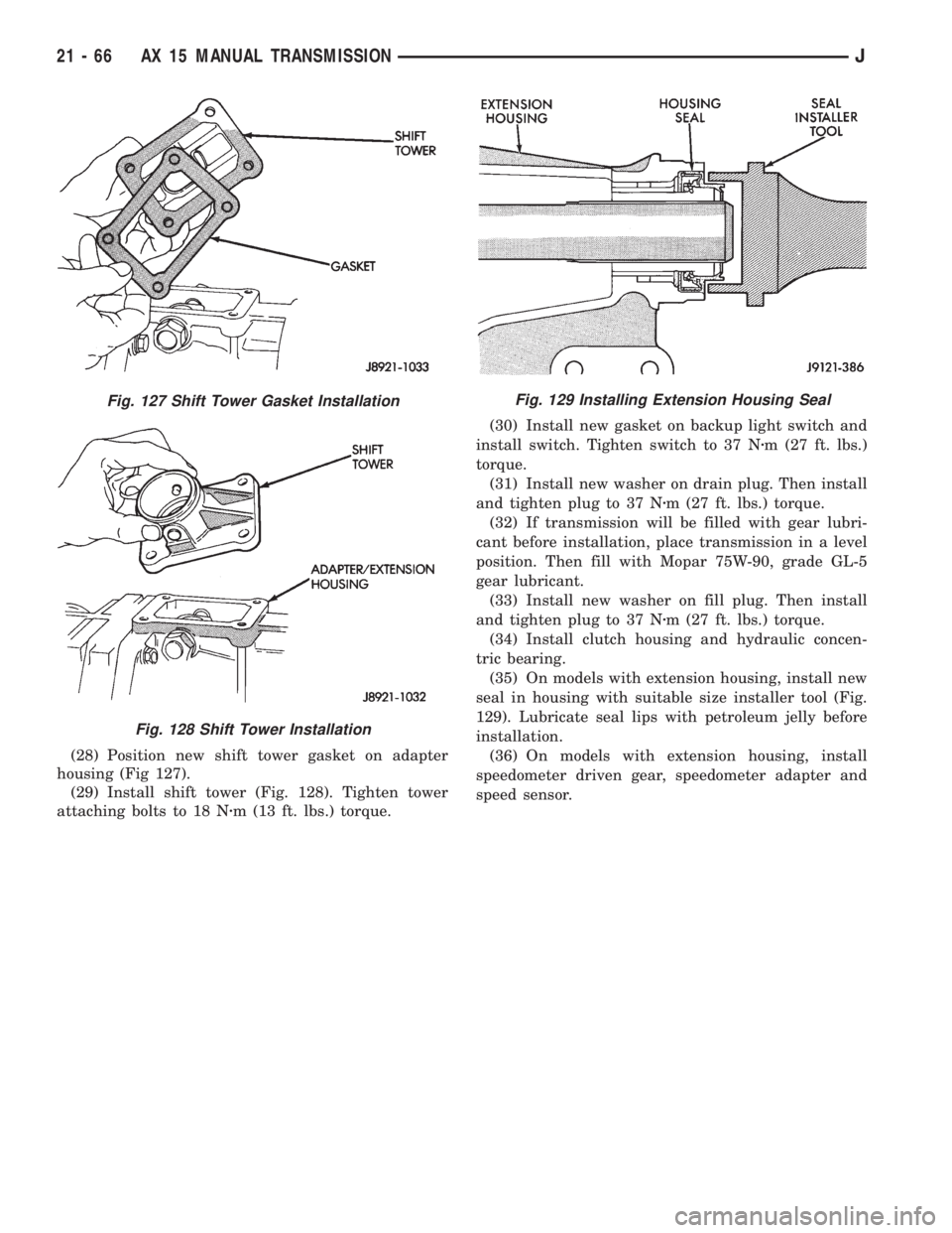
(28) Position new shift tower gasket on adapter
housing (Fig 127).
(29) Install shift tower (Fig. 128). Tighten tower
attaching bolts to 18 Nzm (13 ft. lbs.) torque.(30) Install new gasket on backup light switch and
install switch. Tighten switch to 37 Nzm (27 ft. lbs.)
torque.
(31) Install new washer on drain plug. Then install
and tighten plug to 37 Nzm (27 ft. lbs.) torque.
(32) If transmission will be filled with gear lubri-
cant before installation, place transmission in a level
position. Then fill with Mopar 75W-90, grade GL-5
gear lubricant.
(33) Install new washer on fill plug. Then install
and tighten plug to 37 Nzm (27 ft. lbs.) torque.
(34) Install clutch housing and hydraulic concen-
tric bearing.
(35) On models with extension housing, install new
seal in housing with suitable size installer tool (Fig.
129). Lubricate seal lips with petroleum jelly before
installation.
(36) On models with extension housing, install
speedometer driven gear, speedometer adapter and
speed sensor.
Fig. 127 Shift Tower Gasket Installation
Fig. 128 Shift Tower Installation
Fig. 129 Installing Extension Housing Seal
21 - 66 AX 15 MANUAL TRANSMISSIONJ
Page 1629 of 2158
30RH/32RH AUTOMATIC TRANSMISSION
GENERAL INFORMATION
INDEX
page page
Recommended Fluid....................... 67
Torque Converter......................... 67
Transmission Application.................... 67
Transmission Changes and Parts Interchangeability.. 67
Transmission Controls and Components........ 67
Transmission Identification.................. 67
TRANSMISSION APPLICATION
Chrysler 30RH and 32RH automatic transmissions
are used in XJ/YJ models. Both are 3-speed auto-
matic transmissions with a gear-type oil pump, two
clutches and bands and a planetary gear system (Fig.
1).
The 30RH is used in XJ/YJ models with a 2.5L en-
gine. The 32RH is used in YJ models with a 4.0L en-
gine.
TORQUE CONVERTER
A three element, torque converter is used for all
applications. The converter consists of an impeller,
stator, and turbine.
The converter used with 30RH/32RH transmissions
has a converter clutch. The clutch is engaged by an
electrical solenoid and mechanical module on the
valve body. The solenoid is operated by the power-
train control module.
The torque converter is a welded assembly and is
not a repairable component. The converter is serviced
as an assembly.
RECOMMENDED FLUID
The recommended and preferred fluid for 30RH/
32RH transmissions is Mopar ATF Plus, Type 7176.
Dexron II is not really recommended and should
only be used when ATF Plus is not available.
TRANSMISSION IDENTIFICATION
The transmission identification numbers are
stamped on the left side of the case just above the oil
pan gasket surface (Fig. 2). The first set of numbers
is the transmission part number. The next set of code
numbers set is the date of build. The final set of code
numbers represents the transmission serial number.
TRANSMISSION CHANGES AND PARTS
INTERCHANGEABILITY
1995 transmissions are similar to previous models
but only in appearance. Current transmissions are
dimensionally different. Do not interchange new/oldparts. Different dimensions, fluid passages, input/
output shafts, cases, bands, valve bodies and gover-
nor assemblies are just a few of the changed items.
CAUTION: Special bolts are used to attach the
driveplate to the crankshaft on models with a 2.5L
engine and 30RH transmission,. These bolts have a
smaller hex head for torque converter clearance.
DO NOT interchange these bolts with similar size
bolts for any reason.
Different governor weight assemblies are used in
30RH/32RH transmissions. The 30RH weight assem-
bly is much the same as in previous years. However,
the 32RH has a three stage governor weight assem-
bly consisting of the outer weight, a smaller weight
spring, and a new intermediate weight. Refer to the
overhaul and in-vehicle service sections for more de-
tailed information.
Plastic check balls are now used in many 30RH/
32RH valve bodies. The new check balls entered pro-
duction as a running change. Plastic and steel check
balls are not interchangeable.
A converter drainback check valve has been added
to the fluid cooler system. The one-way valve is lo-
cated in the transmission outlet (pressure) line. The
valve prevents fluid drainback when the vehicle is
parked for lengthy periods.
TRANSMISSION CONTROLS AND COMPONENTS
The transmission hydraulic control system per-
forms five basic functions, which are:
²pressure supply
²pressure regulation
²flow control
²clutch/band apply and release
²lubrication
Pressure Supply And Regulation
The oil pump generates the fluid working pressure
needed for operation and lubrication. The pump is
J30RH/32RH AUTOMATIC TRANSMISSION 21 - 67
Page 1630 of 2158
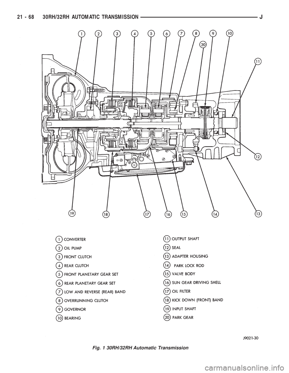
Fig. 1 30RH/32RH Automatic Transmission
21 - 68 30RH/32RH AUTOMATIC TRANSMISSIONJ