JEEP XJ 1995 Service And Repair Manual
Manufacturer: JEEP, Model Year: 1995,
Model line: XJ,
Model: JEEP XJ 1995
Pages: 2158, PDF Size: 81.9 MB
JEEP XJ 1995 Service And Repair Manual
XJ 1995
JEEP
JEEP
https://www.carmanualsonline.info/img/16/57043/w960_57043-0.png
JEEP XJ 1995 Service And Repair Manual
Trending: lock, fuel cap release, fuel pressure, battery capacity, trunk, coolant level, coolant temperature
Page 1581 of 2158
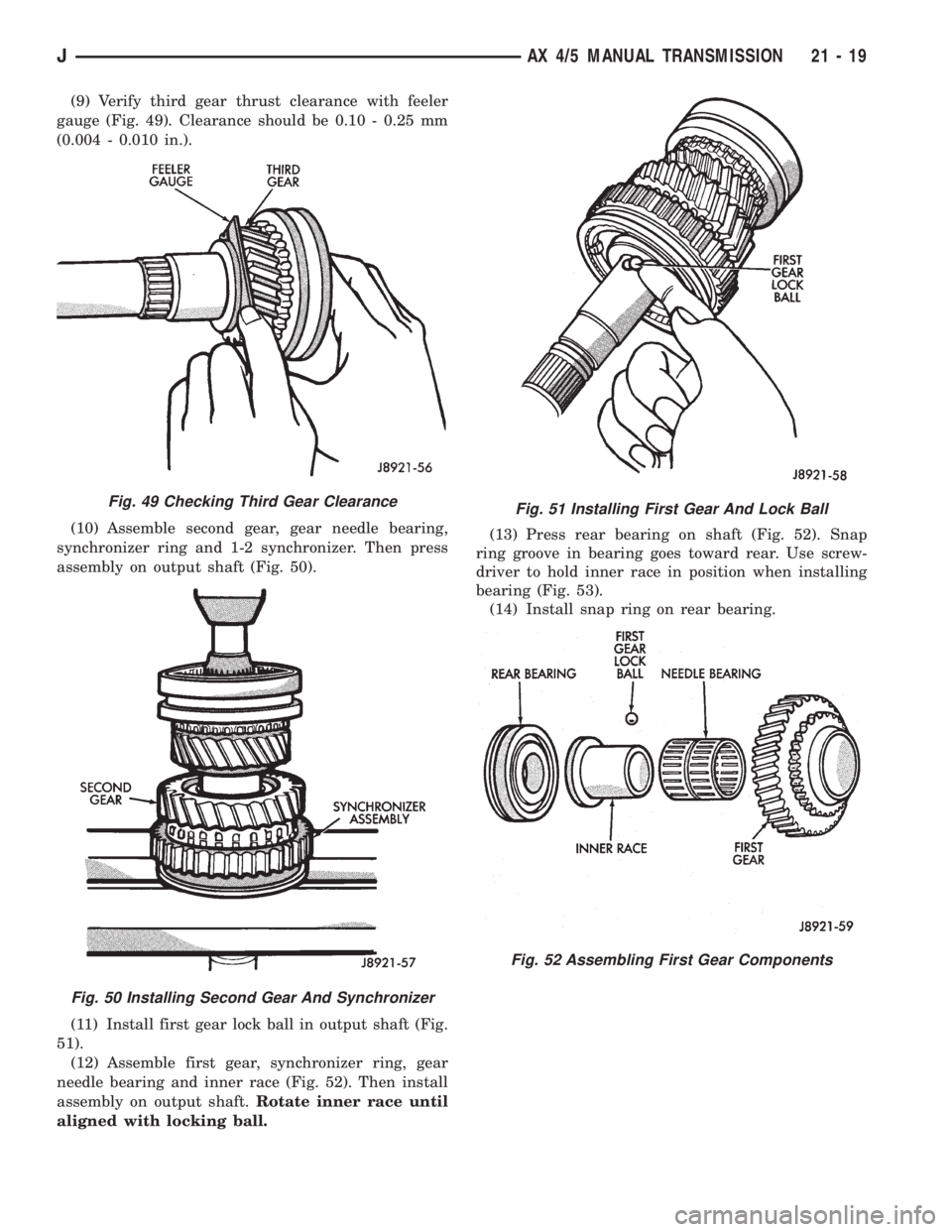
(9) Verify third gear thrust clearance with feeler
gauge (Fig. 49). Clearance should be 0.10 - 0.25 mm
(0.004 - 0.010 in.).
(10) Assemble second gear, gear needle bearing,
synchronizer ring and 1-2 synchronizer. Then press
assembly on output shaft (Fig. 50).
(11) Install first gear lock ball in output shaft (Fig.
51).
(12) Assemble first gear, synchronizer ring, gear
needle bearing and inner race (Fig. 52). Then install
assembly on output shaft.Rotate inner race until
aligned with locking ball.(13) Press rear bearing on shaft (Fig. 52). Snap
ring groove in bearing goes toward rear. Use screw-
driver to hold inner race in position when installing
bearing (Fig. 53).
(14) Install snap ring on rear bearing.
Fig. 49 Checking Third Gear Clearance
Fig. 50 Installing Second Gear And Synchronizer
Fig. 51 Installing First Gear And Lock Ball
Fig. 52 Assembling First Gear Components
JAX 4/5 MANUAL TRANSMISSION 21 - 19
Page 1582 of 2158
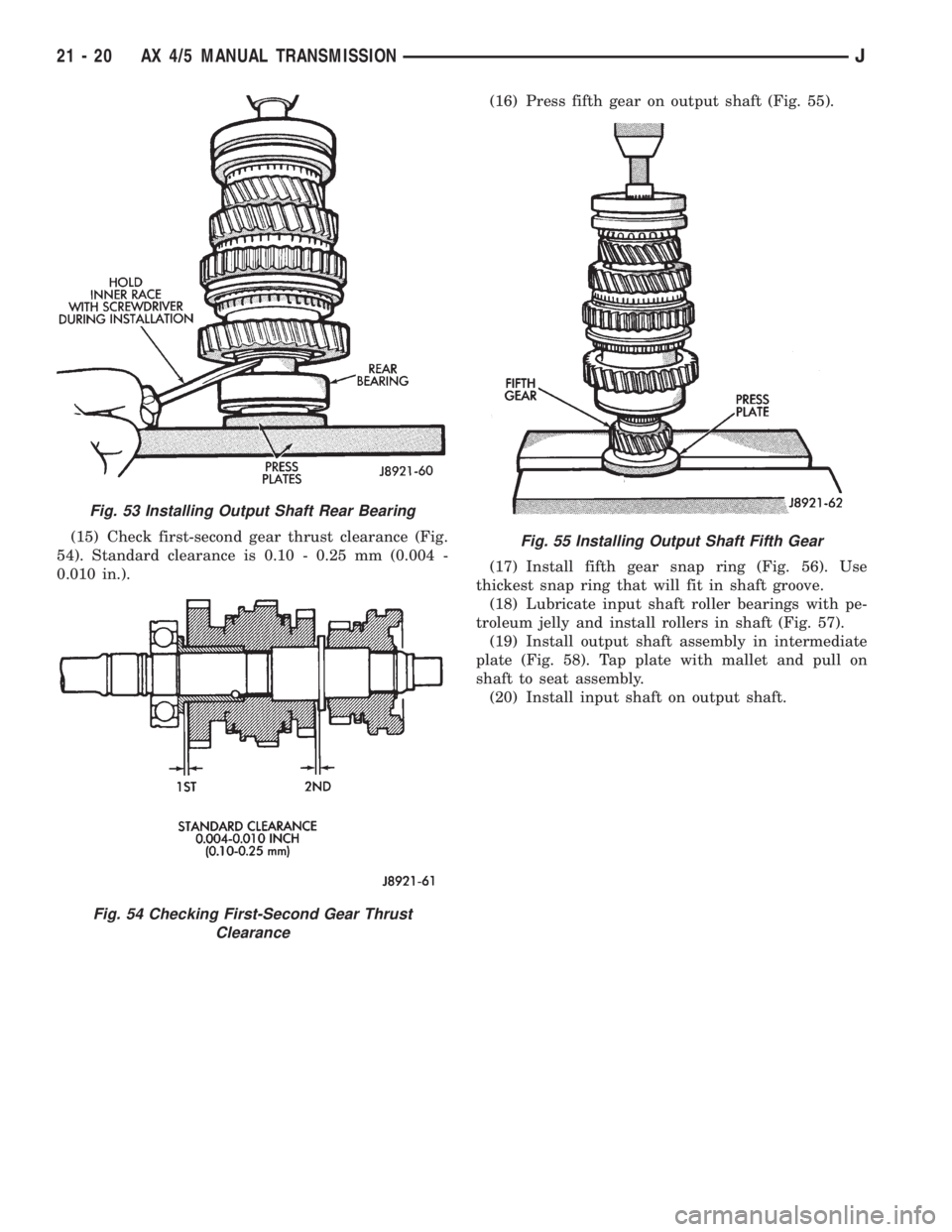
(15) Check first-second gear thrust clearance (Fig.
54). Standard clearance is 0.10 - 0.25 mm (0.004 -
0.010 in.).(16) Press fifth gear on output shaft (Fig. 55).
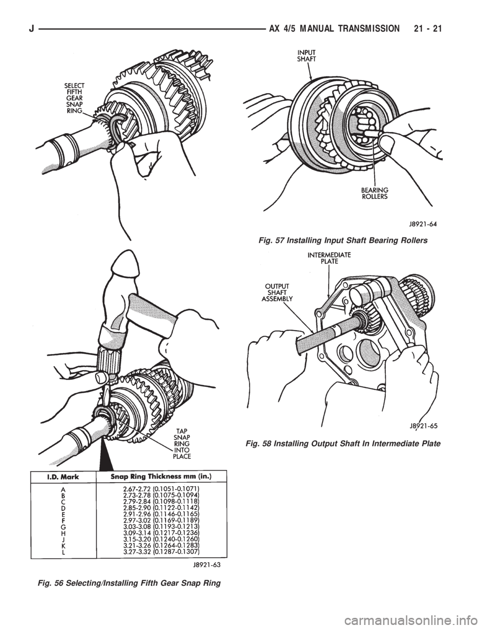
(17) Install fifth gear snap ring (Fig. 56). Use
thickest snap ring that will fit in shaft groove.
(18) Lubricate input shaft roller bearings with pe-
troleum jelly and install rollers in shaft (Fig. 57).
(19) Install output shaft assembly in intermediate
plate (Fig. 58). Tap plate with mallet and pull on
shaft to seat assembly.
(20) Install input shaft on output shaft.
Fig. 53 Installing Output Shaft Rear Bearing
Fig. 54 Checking First-Second Gear Thrust
Clearance
Fig. 55 Installing Output Shaft Fifth Gear
21 - 20 AX 4/5 MANUAL TRANSMISSIONJ
Page 1583 of 2158
Fig. 56 Selecting/Installing Fifth Gear Snap Ring
Fig. 57 Installing Input Shaft Bearing Rollers
Fig. 58 Installing Output Shaft In Intermediate Plate
JAX 4/5 MANUAL TRANSMISSION 21 - 21
Page 1584 of 2158
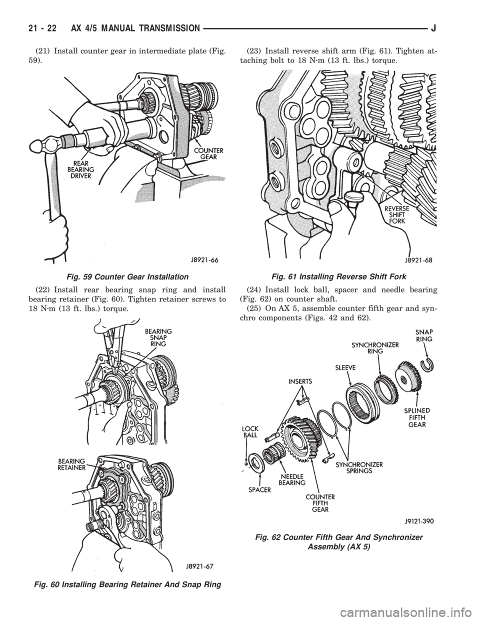
(21) Install counter gear in intermediate plate (Fig.
59).
(22) Install rear bearing snap ring and install
bearing retainer (Fig. 60). Tighten retainer screws to
18 Nzm (13 ft. lbs.) torque.(23) Install reverse shift arm (Fig. 61). Tighten at-
taching bolt to 18 Nzm (13 ft. lbs.) torque.
(24) Install lock ball, spacer and needle bearing
(Fig. 62) on counter shaft.
(25) On AX 5, assemble counter fifth gear and syn-
chro components (Figs. 42 and 62).
Fig. 59 Counter Gear Installation
Fig. 60 Installing Bearing Retainer And Snap Ring
Fig. 61 Installing Reverse Shift Fork
Fig. 62 Counter Fifth Gear And Synchronizer
Assembly (AX 5)
21 - 22 AX 4/5 MANUAL TRANSMISSIONJ
Page 1585 of 2158
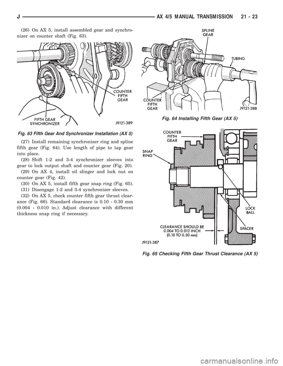
(26) On AX 5, install assembled gear and synchro-
nizer on counter shaft (Fig. 63).
(27) Install remaining synchronizer ring and spline
fifth gear (Fig. 64). Use length of pipe to tap gear
into place.
(28) Shift 1-2 and 3-4 synchronizer sleeves into
gear to lock output shaft and counter gear (Fig. 20).
(29) On AX 4, install oil slinger and lock nut on
counter gear (Fig. 42).
(30) On AX 5, install fifth gear snap ring (Fig. 65).
(31) Disengage 1-2 and 3-4 synchronizer sleeves.
(32) On AX 5, check counter fifth gear thrust clear-
ance (Fig. 66). Standard clearance is 0.10 - 0.30 mm
(0.004 - 0.010 in.). Adjust clearance with different
thickness snap ring if necessary.
Fig. 65 Checking Fifth Gear Thrust Clearance (AX 5)
Fig. 63 Fifth Gear And Synchronizer Installation (AX 5)
Fig. 64 Installing Fifth Gear (AX 5)
JAX 4/5 MANUAL TRANSMISSION 21 - 23
Page 1586 of 2158
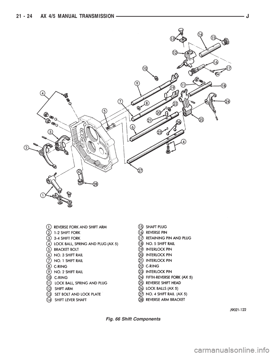
Fig. 66 Shift Components
21 - 24 AX 4/5 MANUAL TRANSMISSIONJ
Page 1587 of 2158
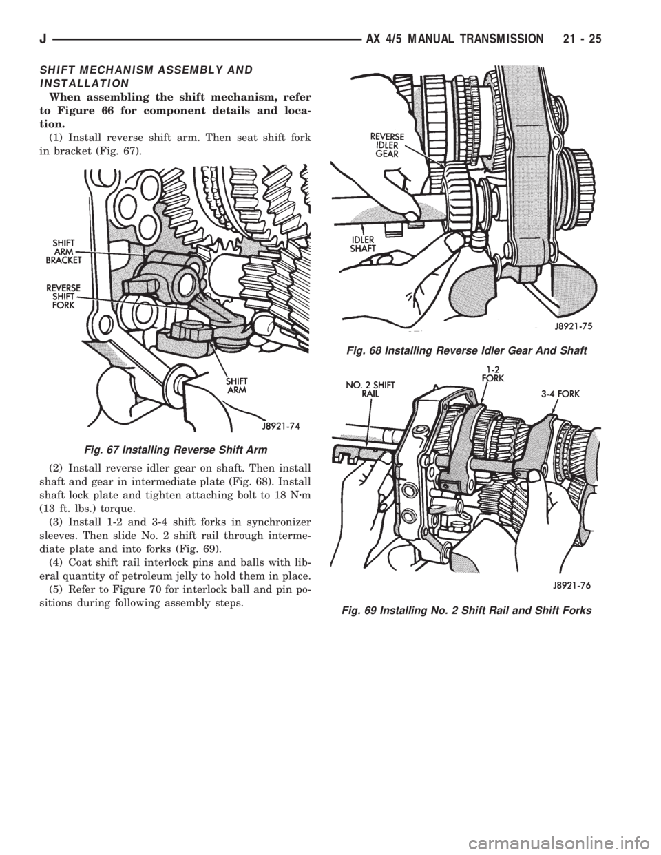
SHIFT MECHANISM ASSEMBLY AND
INSTALLATION
When assembling the shift mechanism, refer
to Figure 66 for component details and loca-
tion.
(1) Install reverse shift arm. Then seat shift fork
in bracket (Fig. 67).
(2) Install reverse idler gear on shaft. Then install
shaft and gear in intermediate plate (Fig. 68). Install
shaft lock plate and tighten attaching bolt to 18 Nzm
(13 ft. lbs.) torque.
(3) Install 1-2 and 3-4 shift forks in synchronizer
sleeves. Then slide No. 2 shift rail through interme-
diate plate and into forks (Fig. 69).
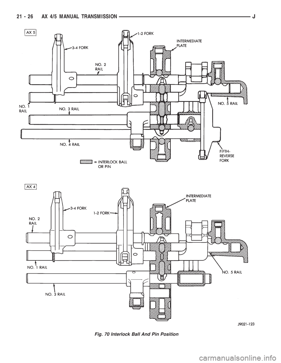
(4) Coat shift rail interlock pins and balls with lib-
eral quantity of petroleum jelly to hold them in place.
(5) Refer to Figure 70 for interlock ball and pin po-
sitions during following assembly steps.
Fig. 68 Installing Reverse Idler Gear And Shaft
Fig. 69 Installing No. 2 Shift Rail and Shift Forks
Fig. 67 Installing Reverse Shift Arm
JAX 4/5 MANUAL TRANSMISSION 21 - 25
Page 1588 of 2158
Fig. 70 Interlock Ball And Pin Position
21 - 26 AX 4/5 MANUAL TRANSMISSIONJ
Page 1589 of 2158
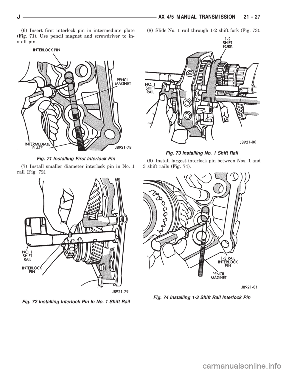
(6) Insert first interlock pin in intermediate plate
(Fig. 71). Use pencil magnet and screwdriver to in-
stall pin.
(7) Install smaller diameter interlock pin in No. 1
rail (Fig. 72).(8) Slide No. 1 rail through 1-2 shift fork (Fig. 73).
(9) Install largest interlock pin between Nos. 1 and
3 shift rails (Fig. 74).
Fig. 71 Installing First Interlock Pin
Fig. 72 Installing Interlock Pin In No. 1 Shift Rail
Fig. 73 Installing No. 1 Shift Rail
Fig. 74 Installing 1-3 Shift Rail Interlock Pin
JAX 4/5 MANUAL TRANSMISSION 21 - 27
Page 1590 of 2158
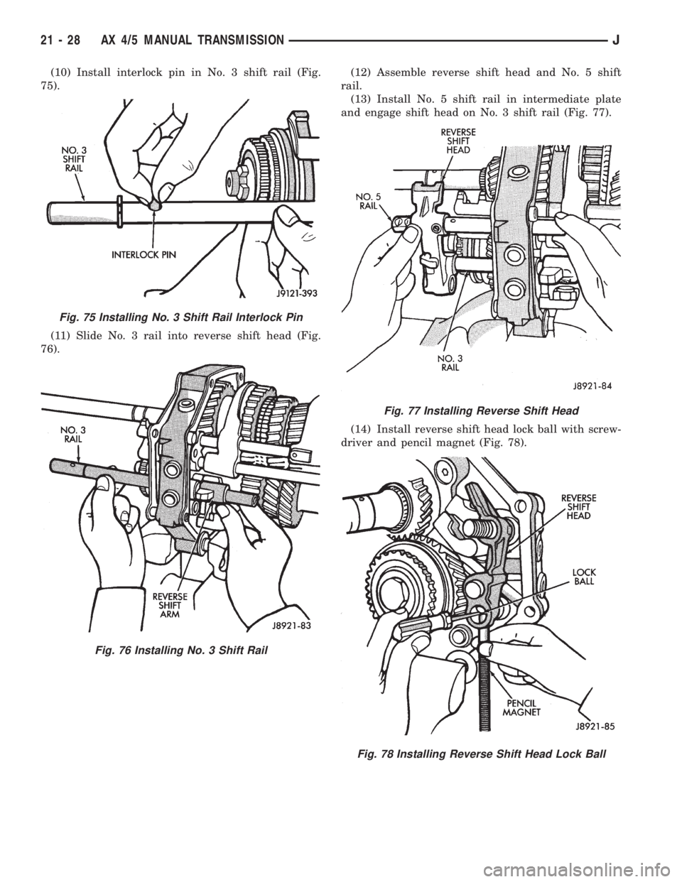
(10) Install interlock pin in No. 3 shift rail (Fig.
75).
(11) Slide No. 3 rail into reverse shift head (Fig.
76).(12) Assemble reverse shift head and No. 5 shift
rail.
(13) Install No. 5 shift rail in intermediate plate
and engage shift head on No. 3 shift rail (Fig. 77).
(14) Install reverse shift head lock ball with screw-
driver and pencil magnet (Fig. 78).
Fig. 75 Installing No. 3 Shift Rail Interlock Pin
Fig. 76 Installing No. 3 Shift Rail
Fig. 77 Installing Reverse Shift Head
Fig. 78 Installing Reverse Shift Head Lock Ball
21 - 28 AX 4/5 MANUAL TRANSMISSIONJ
Trending: spark plugs, fuel consumption, engine oil, maintenance, air conditioning, snow chains, key fob battery
