JEEP XJ 1995 Service And Repair Manual
Manufacturer: JEEP, Model Year: 1995, Model line: XJ, Model: JEEP XJ 1995Pages: 2158, PDF Size: 81.9 MB
Page 1881 of 2158
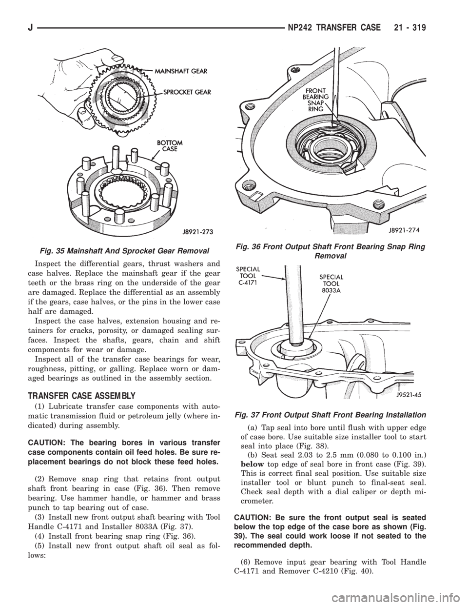
Inspect the differential gears, thrust washers and
case halves. Replace the mainshaft gear if the gear
teeth or the brass ring on the underside of the gear
are damaged. Replace the differential as an assembly
if the gears, case halves, or the pins in the lower case
half are damaged.
Inspect the case halves, extension housing and re-
tainers for cracks, porosity, or damaged sealing sur-
faces. Inspect the shafts, gears, chain and shift
components for wear or damage.
Inspect all of the transfer case bearings for wear,
roughness, pitting, or galling. Replace worn or dam-
aged bearings as outlined in the assembly section.
TRANSFER CASE ASSEMBLY
(1) Lubricate transfer case components with auto-
matic transmission fluid or petroleum jelly (where in-
dicated) during assembly.
CAUTION: The bearing bores in various transfer
case components contain oil feed holes. Be sure re-
placement bearings do not block these feed holes.
(2) Remove snap ring that retains front output
shaft front bearing in case (Fig. 36). Then remove
bearing. Use hammer handle, or hammer and brass
punch to tap bearing out of case.
(3) Install new front output shaft bearing with Tool
Handle C-4171 and Installer 8033A (Fig. 37).
(4) Install front bearing snap ring (Fig. 36).
(5) Install new front output shaft oil seal as fol-
lows:(a) Tap seal into bore until flush with upper edge
of case bore. Use suitable size installer tool to start
seal into place (Fig. 38).
(b) Seat seal 2.03 to 2.5 mm (0.080 to 0.100 in.)
belowtop edge of seal bore in front case (Fig. 39).
This is correct final seal position. Use suitable size
installer tool or blunt punch to final-seat seal.
Check seal depth with a dial caliper or depth mi-
crometer.
CAUTION: Be sure the front output seal is seated
below the top edge of the case bore as shown (Fig.
39). The seal could work loose if not seated to the
recommended depth.
(6) Remove input gear bearing with Tool Handle
C-4171 and Remover C-4210 (Fig. 40).
Fig. 35 Mainshaft And Sprocket Gear RemovalFig. 36 Front Output Shaft Front Bearing Snap Ring
Removal
Fig. 37 Front Output Shaft Front Bearing Installation
JNP242 TRANSFER CASE 21 - 319
Page 1882 of 2158
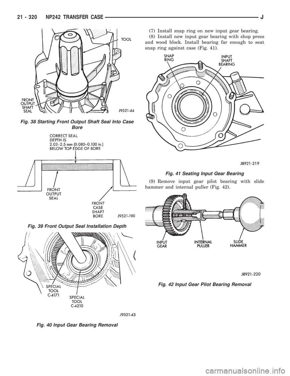
(7) Install snap ring on new input gear bearing.
(8) Install new input gear bearing with shop press
and wood block. Install bearing far enough to seat
snap ring against case (Fig. 41).
(9) Remove input gear pilot bearing with slide
hammer and internal puller (Fig. 42).
Fig. 38 Starting Front Output Shaft Seal Into Case
Bore
Fig. 39 Front Output Seal Installation Depth
Fig. 40 Input Gear Bearing Removal
Fig. 41 Seating Input Gear Bearing
Fig. 42 Input Gear Pilot Bearing Removal
21 - 320 NP242 TRANSFER CASEJ
Page 1883 of 2158
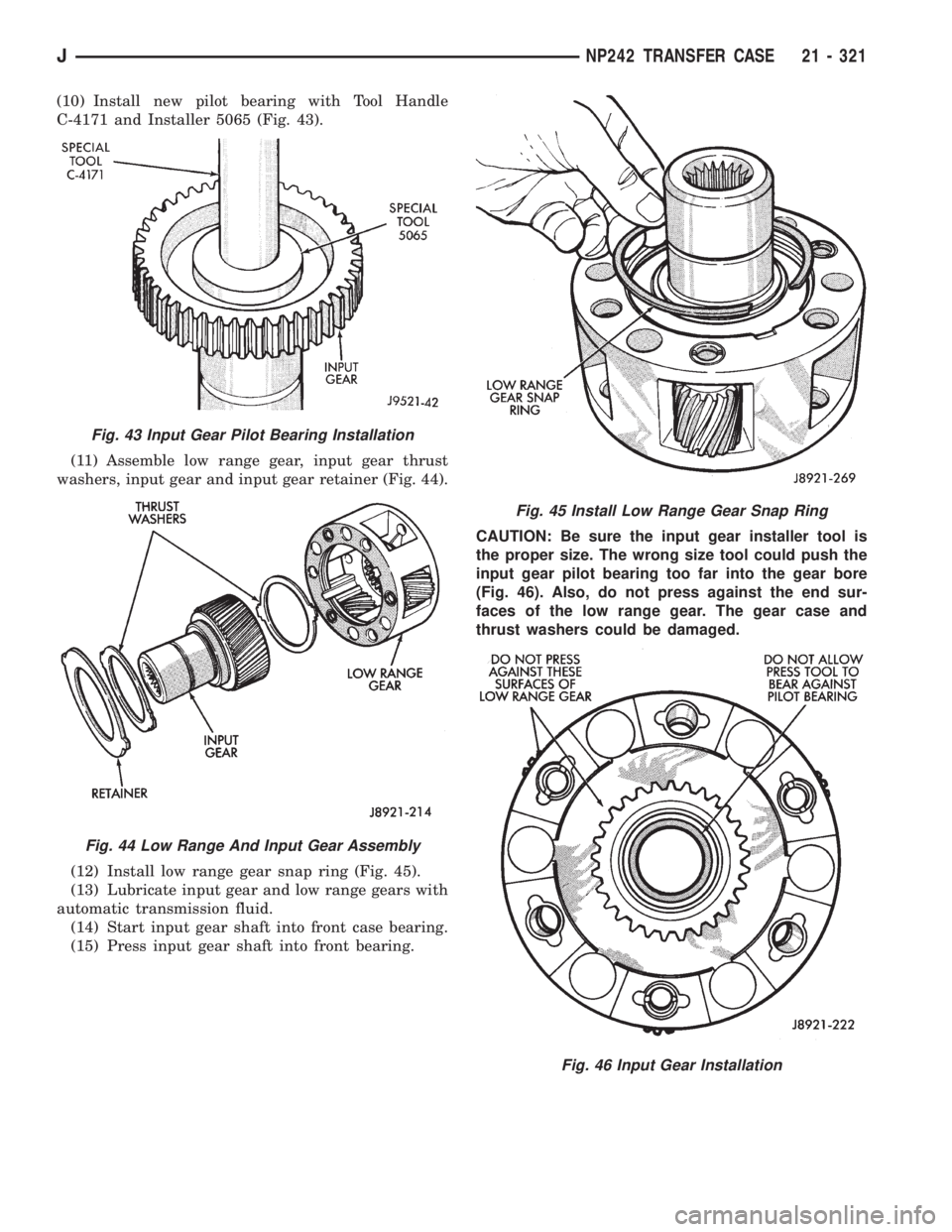
(10) Install new pilot bearing with Tool Handle
C-4171 and Installer 5065 (Fig. 43).
(11) Assemble low range gear, input gear thrust
washers, input gear and input gear retainer (Fig. 44).
(12) Install low range gear snap ring (Fig. 45).
(13) Lubricate input gear and low range gears with
automatic transmission fluid.
(14) Start input gear shaft into front case bearing.
(15) Press input gear shaft into front bearing.CAUTION: Be sure the input gear installer tool is
the proper size. The wrong size tool could push the
input gear pilot bearing too far into the gear bore
(Fig. 46). Also, do not press against the end sur-
faces of the low range gear. The gear case and
thrust washers could be damaged.
Fig. 43 Input Gear Pilot Bearing Installation
Fig. 44 Low Range And Input Gear Assembly
Fig. 45 Install Low Range Gear Snap Ring
Fig. 46 Input Gear Installation
JNP242 TRANSFER CASE 21 - 321
Page 1884 of 2158
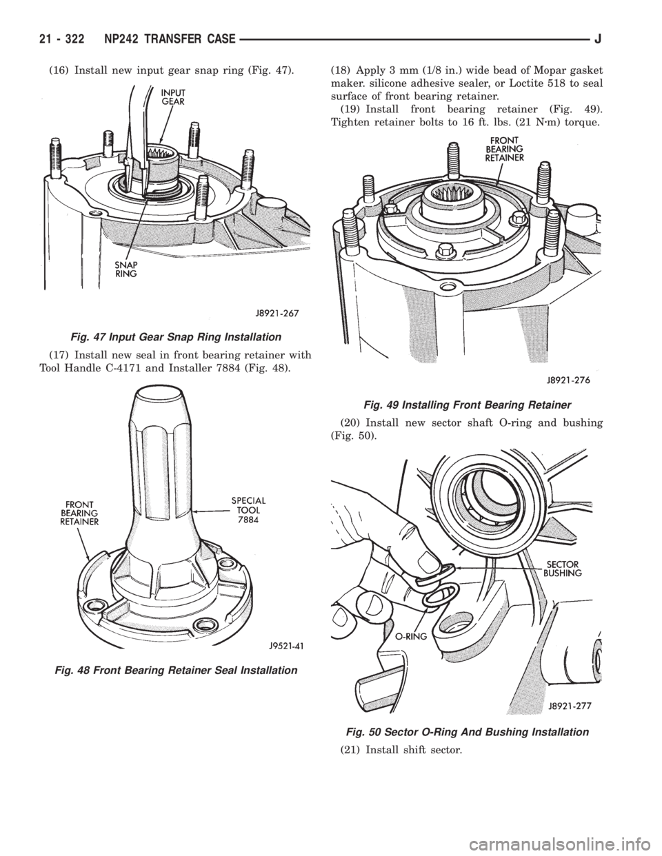
(16) Install new input gear snap ring (Fig. 47).
(17) Install new seal in front bearing retainer with
Tool Handle C-4171 and Installer 7884 (Fig. 48).(18) Apply 3 mm (1/8 in.) wide bead of Mopar gasket
maker. silicone adhesive sealer, or Loctite 518 to seal
surface of front bearing retainer.
(19) Install front bearing retainer (Fig. 49).
Tighten retainer bolts to 16 ft. lbs. (21 Nzm) torque.
(20) Install new sector shaft O-ring and bushing
(Fig. 50).
(21) Install shift sector.
Fig. 47 Input Gear Snap Ring Installation
Fig. 48 Front Bearing Retainer Seal Installation
Fig. 49 Installing Front Bearing Retainer
Fig. 50 Sector O-Ring And Bushing Installation
21 - 322 NP242 TRANSFER CASEJ
Page 1885 of 2158
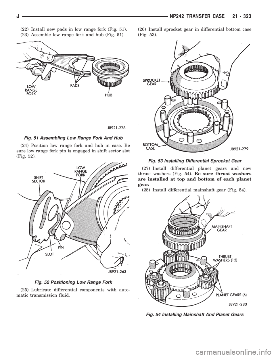
(22) Install new pads in low range fork (Fig. 51).
(23) Assemble low range fork and hub (Fig. 51).
(24) Position low range fork and hub in case. Be
sure low range fork pin is engaged in shift sector slot
(Fig. 52).
(25) Lubricate differential components with auto-
matic transmission fluid.(26) Install sprocket gear in differential bottom case
(Fig. 53).
(27) Install differential planet gears and new
thrust washers (Fig. 54).Be sure thrust washers
are installed at top and bottom of each planet
gear.
(28) Install differential mainshaft gear (Fig. 54).
Fig. 51 Assembling Low Range Fork And Hub
Fig. 52 Positioning Low Range Fork
Fig. 53 Installing Differential Sprocket Gear
Fig. 54 Installing Mainshaft And Planet Gears
JNP242 TRANSFER CASE 21 - 323
Page 1886 of 2158
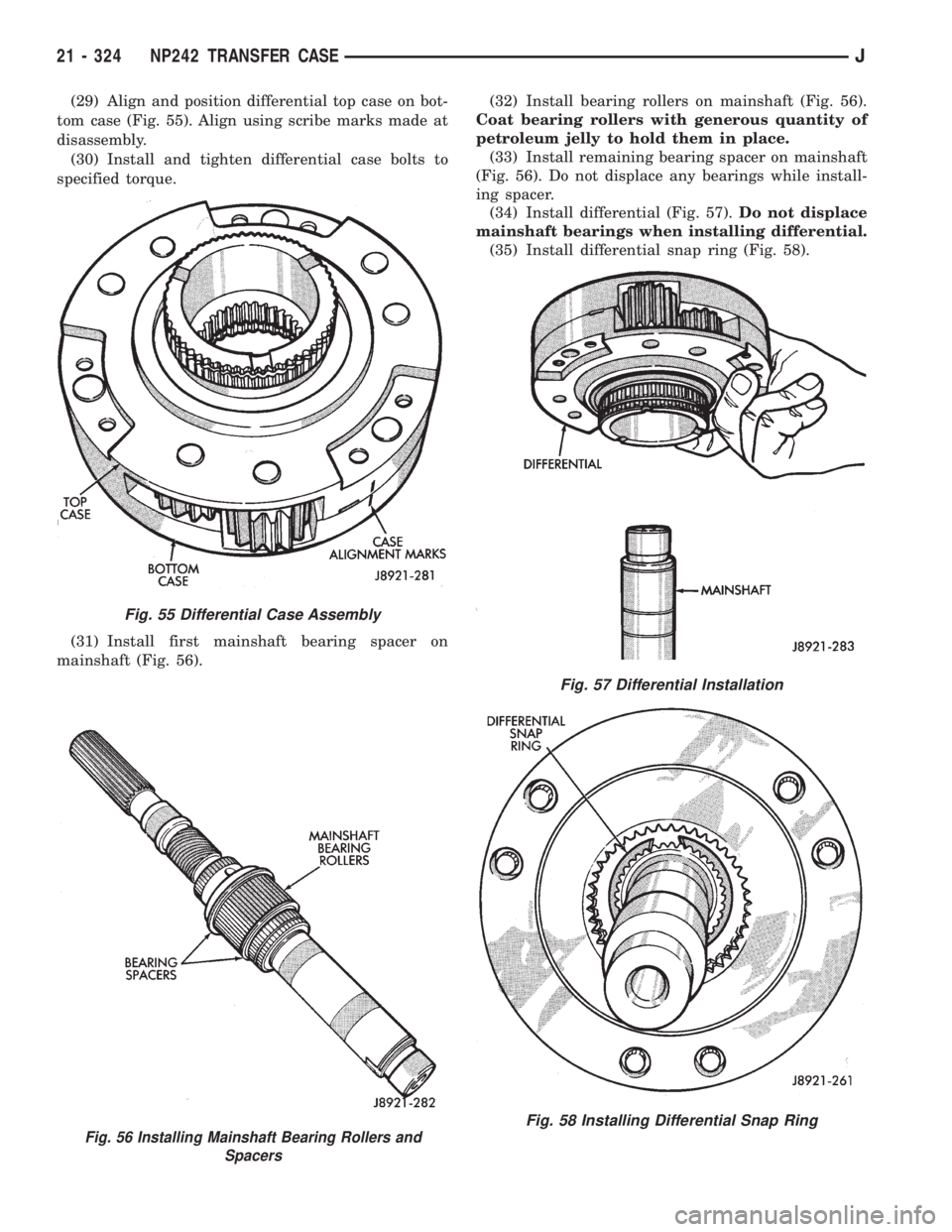
(29) Align and position differential top case on bot-
tom case (Fig. 55). Align using scribe marks made at
disassembly.
(30) Install and tighten differential case bolts to
specified torque.
(31) Install first mainshaft bearing spacer on
mainshaft (Fig. 56).(32) Install bearing rollers on mainshaft (Fig. 56).
Coat bearing rollers with generous quantity of
petroleum jelly to hold them in place.
(33) Install remaining bearing spacer on mainshaft
(Fig. 56). Do not displace any bearings while install-
ing spacer.
(34) Install differential (Fig. 57).Do not displace
mainshaft bearings when installing differential.
(35) Install differential snap ring (Fig. 58).
Fig. 56 Installing Mainshaft Bearing Rollers and
Spacers
Fig. 55 Differential Case Assembly
Fig. 57 Differential Installation
Fig. 58 Installing Differential Snap Ring
21 - 324 NP242 TRANSFER CASEJ
Page 1887 of 2158
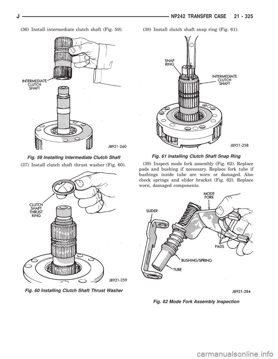
(36) Install intermediate clutch shaft (Fig. 59).
(37) Install clutch shaft thrust washer (Fig. 60).(38) Install clutch shaft snap ring (Fig. 61).
(39) Inspect mode fork assembly (Fig. 62). Replace
pads and bushing if necessary. Replace fork tube if
bushings inside tube are worn or damaged. Also
check springs and slider bracket (Fig. 62). Replace
worn, damaged components.
Fig. 59 Installing Intermediate Clutch Shaft
Fig. 60 Installing Clutch Shaft Thrust Washer
Fig. 61 Installing Clutch Shaft Snap Ring
Fig. 62 Mode Fork Assembly Inspection
JNP242 TRANSFER CASE 21 - 325
Page 1888 of 2158
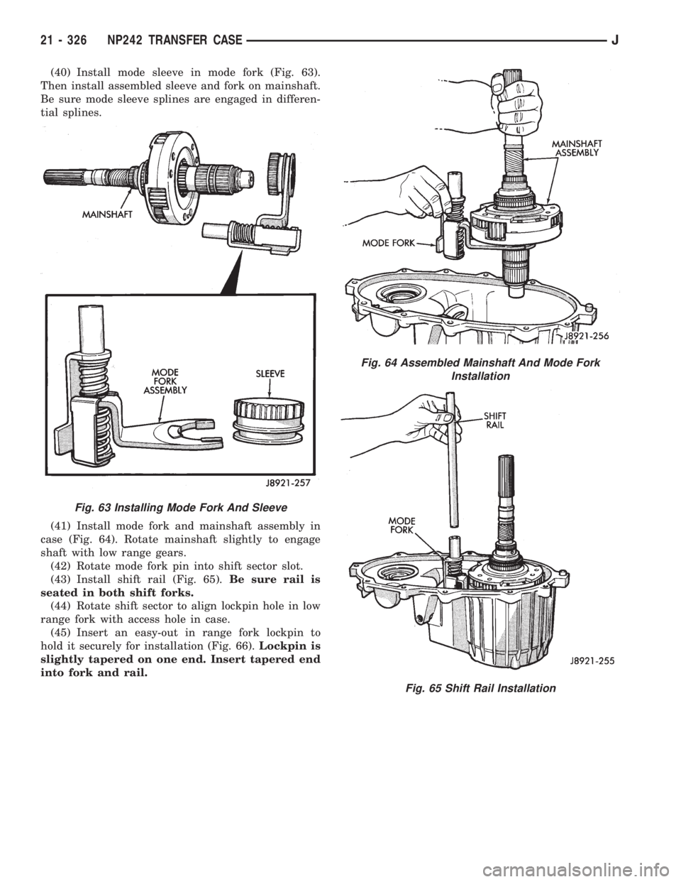
(40) Install mode sleeve in mode fork (Fig. 63).
Then install assembled sleeve and fork on mainshaft.
Be sure mode sleeve splines are engaged in differen-
tial splines.
(41) Install mode fork and mainshaft assembly in
case (Fig. 64). Rotate mainshaft slightly to engage
shaft with low range gears.
(42) Rotate mode fork pin into shift sector slot.
(43) Install shift rail (Fig. 65).Be sure rail is
seated in both shift forks.
(44) Rotate shift sector to align lockpin hole in low
range fork with access hole in case.
(45) Insert an easy-out in range fork lockpin to
hold it securely for installation (Fig. 66).Lockpin is
slightly tapered on one end. Insert tapered end
into fork and rail.
Fig. 63 Installing Mode Fork And Sleeve
Fig. 64 Assembled Mainshaft And Mode Fork
Installation
Fig. 65 Shift Rail Installation
21 - 326 NP242 TRANSFER CASEJ
Page 1889 of 2158
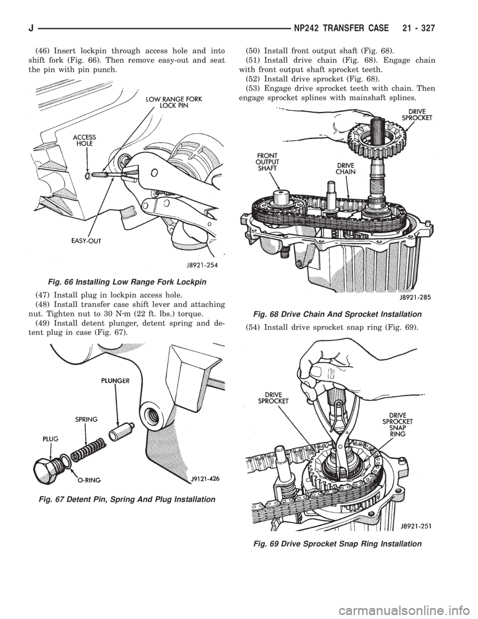
(46) Insert lockpin through access hole and into
shift fork (Fig. 66). Then remove easy-out and seat
the pin with pin punch.
(47) Install plug in lockpin access hole.
(48) Install transfer case shift lever and attaching
nut. Tighten nut to 30 Nzm (22 ft. lbs.) torque.
(49) Install detent plunger, detent spring and de-
tent plug in case (Fig. 67).(50) Install front output shaft (Fig. 68).
(51) Install drive chain (Fig. 68). Engage chain
with front output shaft sprocket teeth.
(52) Install drive sprocket (Fig. 68).
(53) Engage drive sprocket teeth with chain. Then
engage sprocket splines with mainshaft splines.
(54) Install drive sprocket snap ring (Fig. 69).
Fig. 66 Installing Low Range Fork Lockpin
Fig. 67 Detent Pin, Spring And Plug Installation
Fig. 68 Drive Chain And Sprocket Installation
Fig. 69 Drive Sprocket Snap Ring Installation
JNP242 TRANSFER CASE 21 - 327
Page 1890 of 2158
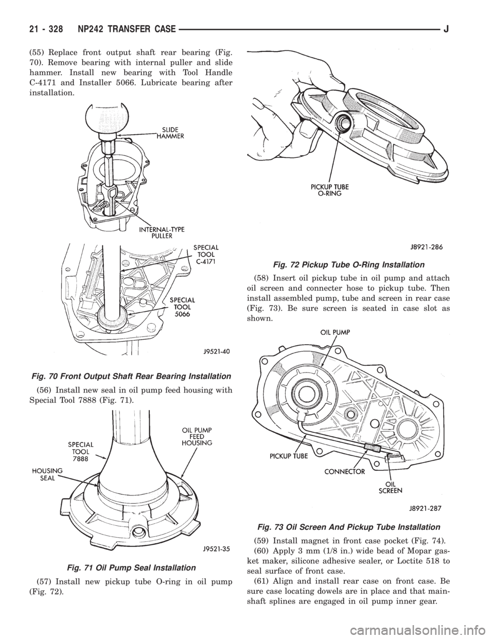
(55) Replace front output shaft rear bearing (Fig.
70). Remove bearing with internal puller and slide
hammer. Install new bearing with Tool Handle
C-4171 and Installer 5066. Lubricate bearing after
installation.
(56) Install new seal in oil pump feed housing with
Special Tool 7888 (Fig. 71).
(57) Install new pickup tube O-ring in oil pump
(Fig. 72).(58) Insert oil pickup tube in oil pump and attach
oil screen and connecter hose to pickup tube. Then
install assembled pump, tube and screen in rear case
(Fig. 73). Be sure screen is seated in case slot as
shown.
(59) Install magnet in front case pocket (Fig. 74).
(60) Apply 3 mm (1/8 in.) wide bead of Mopar gas-
ket maker, silicone adhesive sealer, or Loctite 518 to
seal surface of front case.
(61) Align and install rear case on front case. Be
sure case locating dowels are in place and that main-
shaft splines are engaged in oil pump inner gear.
Fig. 70 Front Output Shaft Rear Bearing Installation
Fig. 71 Oil Pump Seal Installation
Fig. 72 Pickup Tube O-Ring Installation
Fig. 73 Oil Screen And Pickup Tube Installation
21 - 328 NP242 TRANSFER CASEJ