stop start JEEP YJ 1995 Service And User Guide
[x] Cancel search | Manufacturer: JEEP, Model Year: 1995, Model line: YJ, Model: JEEP YJ 1995Pages: 2158, PDF Size: 81.9 MB
Page 336 of 2158
For diagnostics, refer to the appropriate Powertrain
Diagnostic Procedures service manual for operation
of the DRB scan tool.
SPARK PLUGS
For spark plug removal, cleaning, gap adjustment
and installation, refer to the Component Removal/In-
stallation section of this group.
Faulty carbon and/or gas fouled plugs generally
cause hard starting, but they will clean up at higher
engine speeds. Faulty plugs can be identified in a
number of ways: poor fuel economy, power loss, de-
crease in engine speed, hard starting and, in general,
poor engine performance.
Remove the spark plugs and examine them for
burned electrodes and fouled, cracked or broken por-
celain insulators. For identification, keep plugs ar-
ranged in the order in which they were removed from
the engine. An isolated plug displaying an abnormal
condition indicates that a problem exists in the cor-
responding cylinder. Replace spark plugs at the inter-
vals recommended in the maintenance chart in
Group 0, Lubrication and Maintenance.
Spark plugs that have low mileage may be cleaned
and reused if not otherwise defective. Refer to the
following Spark Plug Condition section of this group.
CONDITION
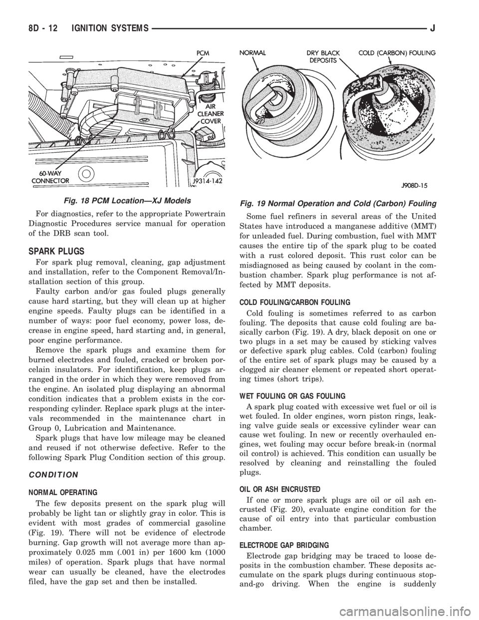
NORMAL OPERATING
The few deposits present on the spark plug will
probably be light tan or slightly gray in color. This is
evident with most grades of commercial gasoline
(Fig. 19). There will not be evidence of electrode
burning. Gap growth will not average more than ap-
proximately 0.025 mm (.001 in) per 1600 km (1000
miles) of operation. Spark plugs that have normal
wear can usually be cleaned, have the electrodes
filed, have the gap set and then be installed.Some fuel refiners in several areas of the United
States have introduced a manganese additive (MMT)
for unleaded fuel. During combustion, fuel with MMT
causes the entire tip of the spark plug to be coated
with a rust colored deposit. This rust color can be
misdiagnosed as being caused by coolant in the com-
bustion chamber. Spark plug performance is not af-
fected by MMT deposits.
COLD FOULING/CARBON FOULING
Cold fouling is sometimes referred to as carbon
fouling. The deposits that cause cold fouling are ba-
sically carbon (Fig. 19). A dry, black deposit on one or
two plugs in a set may be caused by sticking valves
or defective spark plug cables. Cold (carbon) fouling
of the entire set of spark plugs may be caused by a
clogged air cleaner element or repeated short operat-
ing times (short trips).
WET FOULING OR GAS FOULING
A spark plug coated with excessive wet fuel or oil is
wet fouled. In older engines, worn piston rings, leak-
ing valve guide seals or excessive cylinder wear can
cause wet fouling. In new or recently overhauled en-
gines, wet fouling may occur before break-in (normal
oil control) is achieved. This condition can usually be
resolved by cleaning and reinstalling the fouled
plugs.
OIL OR ASH ENCRUSTED
If one or more spark plugs are oil or oil ash en-
crusted (Fig. 20), evaluate engine condition for the
cause of oil entry into that particular combustion
chamber.
ELECTRODE GAP BRIDGING
Electrode gap bridging may be traced to loose de-
posits in the combustion chamber. These deposits ac-
cumulate on the spark plugs during continuous stop-
and-go driving. When the engine is suddenly
Fig. 18 PCM LocationÐXJ ModelsFig. 19 Normal Operation and Cold (Carbon) Fouling
8D - 12 IGNITION SYSTEMSJ
Page 353 of 2158
IGNITION SWITCHÐYJ MODELS
GENERAL INFORMATION
This section will cover the electrical portion
of the ignition switch. To service the mechani-
cal ignition key switch, refer to Group 19,
Steering.
Refer to Group 8W, Wiring for ignition switch wir-
ing circuits.
The ignition switch is mounted under the instru-
ment panel on the lower section of the steering col-
umn. The headlamp dimmer switch is mounted
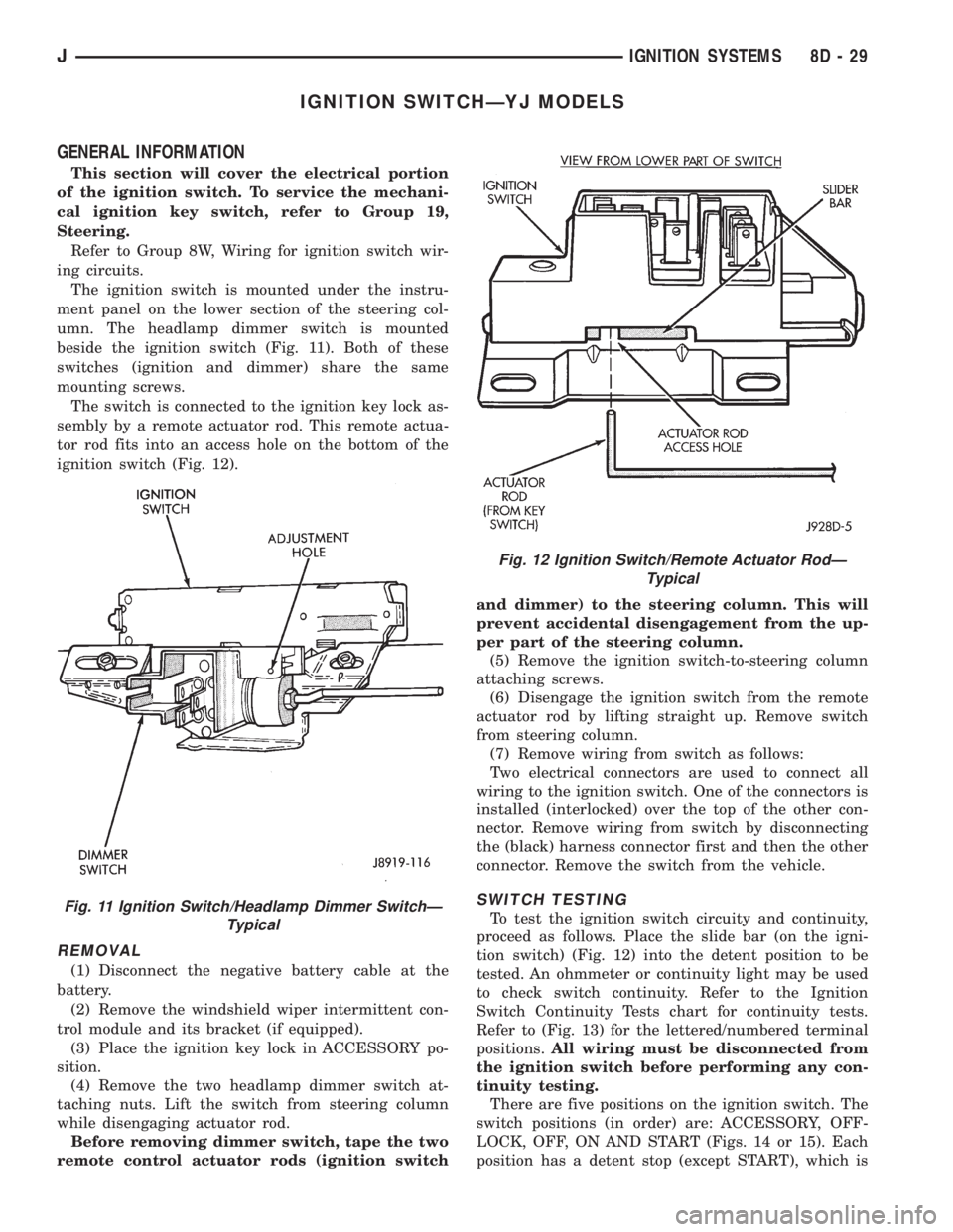
beside the ignition switch (Fig. 11). Both of these
switches (ignition and dimmer) share the same
mounting screws.
The switch is connected to the ignition key lock as-
sembly by a remote actuator rod. This remote actua-
tor rod fits into an access hole on the bottom of the
ignition switch (Fig. 12).
REMOVAL
(1) Disconnect the negative battery cable at the
battery.
(2) Remove the windshield wiper intermittent con-
trol module and its bracket (if equipped).
(3) Place the ignition key lock in ACCESSORY po-
sition.
(4) Remove the two headlamp dimmer switch at-
taching nuts. Lift the switch from steering column
while disengaging actuator rod.
Before removing dimmer switch, tape the two
remote control actuator rods (ignition switchand dimmer) to the steering column. This will
prevent accidental disengagement from the up-
per part of the steering column.
(5) Remove the ignition switch-to-steering column
attaching screws.
(6) Disengage the ignition switch from the remote
actuator rod by lifting straight up. Remove switch
from steering column.
(7) Remove wiring from switch as follows:
Two electrical connectors are used to connect all
wiring to the ignition switch. One of the connectors is
installed (interlocked) over the top of the other con-
nector. Remove wiring from switch by disconnecting
the (black) harness connector first and then the other
connector. Remove the switch from the vehicle.
SWITCH TESTING
To test the ignition switch circuity and continuity,
proceed as follows. Place the slide bar (on the igni-
tion switch) (Fig. 12) into the detent position to be
tested. An ohmmeter or continuity light may be used
to check switch continuity. Refer to the Ignition
Switch Continuity Tests chart for continuity tests.
Refer to (Fig. 13) for the lettered/numbered terminal
positions.All wiring must be disconnected from
the ignition switch before performing any con-
tinuity testing.
There are five positions on the ignition switch. The
switch positions (in order) are: ACCESSORY, OFF-
LOCK, OFF, ON AND START (Figs. 14 or 15). Each
position has a detent stop (except START), which isFig. 11 Ignition Switch/Headlamp Dimmer SwitchÐ
Typical
Fig. 12 Ignition Switch/Remote Actuator RodÐ
Typical
JIGNITION SYSTEMS 8D - 29
Page 360 of 2158
HEADLAMP HIGH BEAM INDICATOR LAMP
The high beam indicator lamp is controlled by the
headlamp dimmer (multi-function) switch. One side
of the indicator bulb is grounded at all times. The
other side of the bulb receives battery feed through
the contacts of the dimmer switch when the multi-
function switch stalk is actuated to turn the head-
lamp high beams on. Refer to Group 8L - Lamps for
more information.
LOW FUEL WARNING LAMP
A Light-Emitting Diode (LED) on the face of the
fuel gauge will light when the fuel level falls below
approximately 4 gallons. A low fuel warning module
attached to the rear of the fuel gauge controls when
the LED will light. When the module senses 66.5
ohms or more resistance from the fuel level sending
unit for 10 continuous seconds, the LED will light.
When the module senses 63.5 ohms or less resistance
from the fuel level sending unit for 20 continuous
seconds, the LED is turned off.
LOW OIL PRESSURE WARNING LAMP
The low oil pressure warning lamp lights with the
ignition switch in the ON position and the engine not
running. The lamp should be off when the engine is
running. Battery voltage is supplied to one side of
the indicator bulb when the ignition switch is turned
ON. The warning lamp side of the combination oil
pressure sending unit is connected to the other side
of the bulb. When normal engine oil pressure is ap-
plied to the sending unit, resistance on the warning
lamp side is high and the lamp goes off. When engine
oil pressure is too low, resistance on the warning
lamp side of the sending unit is low, which causes
the bulb to light.
LOW WASHER FLUID WARNING LAMP
The low washer fluid warning lamp indicates when
the fluid level in the washer reservoir is too low. The
washer fluid level sensor uses a float in the reservoir
to monitor fluid level. The action of the float opens or
closes the switch within the sensor that provides ig-
nition-switched battery voltage to the lamp bulb. Re-
fer to Group 8K - Wiper and Washer Systems for
more information.
MALFUNCTION INDICATOR LAMP
The CHECK ENGINE or Malfunction Indicator
Lamp (MIL) lights each time the ignition switch is
turned ON, and stays on for 3 seconds as a bulb test.
If the Powertrain Control Module (PCM) receives an
incorrect signal or no signal from certain fuel oremission system related circuits or components, the
lamp is turned on. This will indicate that the PCM
has recorded a Diagnostic Trouble Code (DTC) in
electronic memory for a circuit or component mal-
function. Refer to Group 14 - Fuel System for more
information.
SEAT BELT REMINDER LAMP
The seat belt reminder lamp lights for 4 to 8 sec-
onds after the ignition switch is turned to the ON po-
sition. A timer in the chime/buzzer module controls
ignition-switched battery feed to the lamp. Refer to
Group 8U - Chime/Buzzer Warning Systems for more
information.
TURN SIGNAL INDICATOR LAMPS
The left and right turn signal indicator lamps are
controlled by the turn signal and hazard warning
(multi-function) switches. One side of the bulb for
each lamp is grounded at all times. The other side of
the bulb receives battery feed through the contacts of
the multi-function switch when the turn signal lever
(multi-function switch stalk) or hazard warning but-
ton are actuated. Refer to Group 8J - Turn Signal
and Hazard Warning Systems for more information.
UPSHIFT INDICATOR LAMP
Vehicles equipped with manual transmissions have
an optional upshift indicator lamp. Ground feed for
the lamp is switched by the Powertrain Control Mod-
ule (PCM). The lamp lights to indicate when the
driver should shift to the next highest gear for best
fuel economy. The PCM will turn the lamp off after 3
to 5 seconds if the upshift is not performed. The lamp
will remain off until the vehicle stops accelerating
and is brought back to the range of lamp operation,
or until the transmission is shifted into another gear.
The indicator lamp is normally on when the igni-
tion switch is turned ON and is turned off when the
engine is started. The lamp will be turned on during
vehicle operation according to engine speed and load.
CLUSTER ILLUMINATION LAMPS
All cluster illumination lamps receive battery feed
from the instrument lamps fuse in the fuseblock
module through the panel dimmer rheostat of the
headlamp switch. When the park or headlamps are
on, the cluster illumination lamps light. Illumination
brightness can be adjusted by rotating the headlamp
switch knob (clockwise to dim, counterclockwise to
brighten).
8E - 4 INSTRUMENT PANEL AND GAUGESÐXJJ
Page 382 of 2158
voltage is supplied to one side of the indicator bulb. A
ground path for the bulb is provided by 3 switches.
The bulb will light when:
²the brake warning switch is closed (indicating un-
equal brake system hydraulic pressures possibly due
to brake fluid leakage)
²the ignition switch is in the START position (bulb
test)
²the parking brake switch is closed (parking brake
is applied).
Refer to Group 5 - Brakes for more information.
FOUR-WHEEL DRIVE INDICATOR LAMP
This lamp lights when the transfer case is engaged
in the 4H or 4L position. Voltage is supplied to one
side of the indicator bulb. A switch on the front axle
disconnect housing is connected to the other side of
the indicator bulb. When the switch is closed, a path
to ground is provided and the indicator bulb lights.
HEADLAMP HIGH BEAM INDICATOR LAMP
The high beam indicator lamp is controlled by the
headlamp dimmer switch. One side of the indicator
bulb is grounded at all times. The other side of the
bulb receives battery feed through the contacts of the
dimmer switch when the turn signal switch lever is
actuated to turn the headlamp high beams on. Refer
to Group 8L - Lamps for more information.
MALFUNCTION INDICATOR LAMP
The CHECK ENGINE or Malfunction Indicator
Lamp (MIL) lights each time the ignition switch is
turned ON, and stays on for 3 seconds as a bulb test.
If the Powertrain Control Module (PCM) receives an
incorrect signal or no signal from certain fuel or
emission system related circuits or components, the
lamp is turned on. This will indicate that the PCM
has recorded a Diagnostic Trouble Code (DTC) in
electronic memory for a circuit or component mal-
function. Refer to Group 14 - Fuel System for more
information.
SEAT BELT REMINDER LAMP
The seat belt reminder lamp lights for 4 to 8 sec-
onds after the ignition switch is turned to the ON po-sition. A timer in the chime/buzzer module controls
ignition-switched battery feed to the lamp. Refer to
Group 8U - Chime/Buzzer Warning Systems for more
information.
TURN SIGNAL INDICATOR LAMPS
The left and right turn signal indicator lamps are
controlled by the turn signal and hazard warning
switches. One side of the bulb for each lamp is
grounded at all times. The other side of the bulb re-
ceives battery feed through the contacts of the turn
signal switch, when the turn signal lever or hazard
warning button are actuated. Refer to Group 8J -
Turn Signal and Hazard Warning Systems for more
information.
UPSHIFT INDICATOR LAMP
Vehicles equipped with manual transmissions have
an optional upshift indicator lamp. Ground feed for
the lamp is switched by the Powertrain Control Mod-
ule (PCM). The lamp lights to indicate when the
driver should shift to the next highest gear for best
fuel economy. The PCM will turn the lamp off after 3
to 5 seconds if the upshift is not performed. The lamp
will remain off until the vehicle stops accelerating
and is brought back to the range of lamp operation,
or until the transmission is shifted into another gear.
The indicator lamp is normally on when the igni-
tion switch is turned ON and is turned off when the
engine is started. The lamp will be turned on during
vehicle operation according to engine speed and load.
CLUSTER ILLUMINATION LAMPS
All cluster illumination lamps receive battery feed
from the instrument lamps fuse in the fuseblock
module through the panel dimmer switch. When the
park or headlamps are on, the cluster illumination
lamps light. Illumination brightness can be adjusted
by rotating the panel dimmer thumb-wheel, which is
next to the headlamp switch.
8E - 26 INSTRUMENT PANEL AND GAUGESÐYJJ
Page 422 of 2158
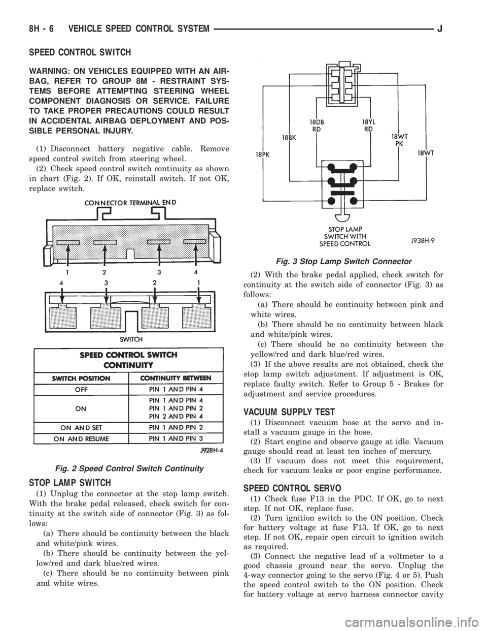
SPEED CONTROL SWITCH
WARNING: ON VEHICLES EQUIPPED WITH AN AIR-
BAG, REFER TO GROUP 8M - RESTRAINT SYS-
TEMS BEFORE ATTEMPTING STEERING WHEEL
COMPONENT DIAGNOSIS OR SERVICE. FAILURE
TO TAKE PROPER PRECAUTIONS COULD RESULT
IN ACCIDENTAL AIRBAG DEPLOYMENT AND POS-
SIBLE PERSONAL INJURY.
(1) Disconnect battery negative cable. Remove
speed control switch from steering wheel.
(2) Check speed control switch continuity as shown
in chart (Fig. 2). If OK, reinstall switch. If not OK,
replace switch.
STOP LAMP SWITCH
(1) Unplug the connector at the stop lamp switch.
With the brake pedal released, check switch for con-
tinuity at the switch side of connector (Fig. 3) as fol-
lows:
(a) There should be continuity between the black
and white/pink wires.
(b) There should be continuity between the yel-
low/red and dark blue/red wires.
(c) There should be no continuity between pink
and white wires.(2) With the brake pedal applied, check switch for
continuity at the switch side of connector (Fig. 3) as
follows:
(a) There should be continuity between pink and
white wires.
(b) There should be no continuity between black
and white/pink wires.
(c) There should be no continuity between the
yellow/red and dark blue/red wires.
(3) If the above results are not obtained, check the
stop lamp switch adjustment. If adjustment is OK,
replace faulty switch. Refer to Group 5 - Brakes for
adjustment and service procedures.
VACUUM SUPPLY TEST
(1) Disconnect vacuum hose at the servo and in-
stall a vacuum gauge in the hose.
(2) Start engine and observe gauge at idle. Vacuum
gauge should read at least ten inches of mercury.
(3) If vacuum does not meet this requirement,
check for vacuum leaks or poor engine performance.
SPEED CONTROL SERVO
(1) Check fuse F13 in the PDC. If OK, go to next
step. If not OK, replace fuse.
(2) Turn ignition switch to the ON position. Check
for battery voltage at fuse F13. If OK, go to next
step. If not OK, repair open circuit to ignition switch
as required.
(3) Connect the negative lead of a voltmeter to a
good chassis ground near the servo. Unplug the
4-way connector going to the servo (Fig. 4 or 5). Push
the speed control switch to the ON position. Check
for battery voltage at servo harness connector cavity
Fig. 2 Speed Control Switch Continuity
Fig. 3 Stop Lamp Switch Connector
8H - 6 VEHICLE SPEED CONTROL SYSTEMJ
Page 557 of 2158
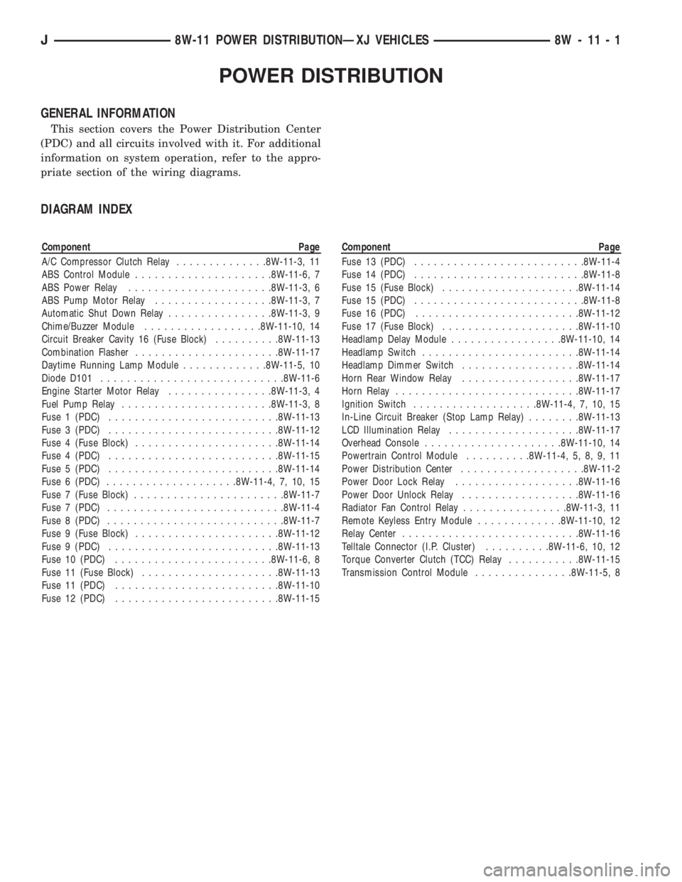
POWER DISTRIBUTION
GENERAL INFORMATION
This section covers the Power Distribution Center
(PDC) and all circuits involved with it. For additional
information on system operation, refer to the appro-
priate section of the wiring diagrams.
DIAGRAM INDEX
Component Page
A/C Compressor Clutch Relay..............8W-11-3, 11
ABS Control Module.....................8W-11-6, 7
ABS Power Relay......................8W-11-3, 6
ABS Pump Motor Relay..................8W-11-3, 7
Automatic Shut Down Relay................8W-11-3, 9
Chime/Buzzer Module..................8W-11-10, 14
Circuit Breaker Cavity 16 (Fuse Block)..........8W-11-13
Combination Flasher......................8W-11-17
Daytime Running Lamp Module.............8W-11-5, 10
Diode D101............................8W-11-6
Engine Starter Motor Relay................8W-11-3, 4
Fuel Pump Relay.......................8W-11-3, 8
Fuse 1 (PDC)..........................8W-11-13
Fuse 3 (PDC)..........................8W-11-12
Fuse 4 (Fuse Block)......................8W-11-14
Fuse 4 (PDC)..........................8W-11-15
Fuse 5 (PDC)..........................8W-11-14
Fuse 6 (PDC)....................8W-11-4, 7, 10, 15
Fuse 7 (Fuse Block).......................8W-11-7
Fuse 7 (PDC)...........................8W-11-4
Fuse 8 (PDC)...........................8W-11-7
Fuse 9 (Fuse Block)......................8W-11-12
Fuse 9 (PDC)..........................8W-11-13
Fuse 10 (PDC)........................8W-11-6, 8
Fuse 11 (Fuse Block).....................8W-11-13
Fuse 11 (PDC).........................8W-11-10
Fuse 12 (PDC).........................8W-11-15Component Page
Fuse 13 (PDC)..........................8W-11-4
Fuse 14 (PDC)..........................8W-11-8
Fuse 15 (Fuse Block).....................8W-11-14
Fuse 15 (PDC)..........................8W-11-8
Fuse 16 (PDC).........................8W-11-12
Fuse 17 (Fuse Block).....................8W-11-10
Headlamp Delay Module.................8W-11-10, 14
Headlamp Switch........................8W-11-14
Headlamp Dimmer Switch..................8W-11-14
Horn Rear Window Relay..................8W-11-17
Horn Relay............................8W-11-17
Ignition Switch...................8W-11-4, 7, 10, 15
In-Line Circuit Breaker (Stop Lamp Relay)........8W-11-13
LCD Illumination Relay....................8W-11-17
Overhead Console.....................8W-11-10, 14
Powertrain Control Module..........8W-11-4, 5, 8, 9, 11
Power Distribution Center...................8W-11-2
Power Door Lock Relay...................8W-11-16
Power Door Unlock Relay..................8W-11-16
Radiator Fan Control Relay................8W-11-3, 11
Remote Keyless Entry Module.............8W-11-10, 12
Relay Center...........................8W-11-16
Telltale Connector (I.P. Cluster)..........8W-11-6, 10, 12
Torque Converter Clutch (TCC) Relay...........8W-11-15
Transmission Control Module...............8W-11-5, 8
J8W-11 POWER DISTRIBUTIONÐXJ VEHICLES 8W - 11 - 1
Page 609 of 2158
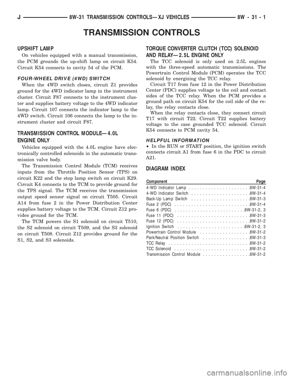
TRANSMISSION CONTROLS
UPSHIFT LAMP
On vehicles equipped with a manual transmission,
the PCM grounds the up-shift lamp on circuit K54.
Circuit K54 connects to cavity 54 of the PCM.
FOUR-WHEEL DRIVE (4WD) SWITCH
When the 4WD switch closes, circuit Z1 provides
ground for the 4WD indicator lamp in the instrument
cluster. Circuit F87 connects to the instrument clus-
ter and supplies battery voltage to the 4WD indicator
lamp. Circuit 107 connects the indicator lamp to the
4WD switch. Circuit 106 connects the lamp to the in-
strument cluster and circuit F87.
TRANSMISSION CONTROL MODULEÐ4.0L
ENGINE ONLY
Vehicles equipped with the 4.0L engine have elec-
tronically controlled solenoids in the automatic trans-
mission valve body.
The Transmission Control Module (TCM) receives
inputs from the Throttle Position Sensor (TPS) on
circuit K22 and the stop lamp switch on circuit K29.
Circuit K4 connects to the TCM to provide ground for
the TPS signal. The TCM receives the transmission
output speed sensor signal on circuit T505. Circuit
A14 from fuse 2 in the Power Distribution Center
supplies battery voltage to the TCM. Circuit Z12 pro-
vides ground for the TCM.
The TCM powers the S1 solenoid on circuit T510,
the S2 solenoid on circuit T509, and the S3 solenoid
on circuit T508. Circuit Z12 provides ground for the
S1, S2, and S3 solenoids.
TORQUE CONVERTER CLUTCH (TCC) SOLENOID
AND RELAYÐ2.5L ENGINE ONLY
The TCC solenoid is only used on 2.5L engines
with the three-speed automatic transmissions. The
Powertrain Control Module (PCM) operates the TCC
solenoid by energizing the TCC relay.
Circuit T17 from fuse 12 in the Power Distribution
Center (PDC) supplies voltage to the coil and contact
sides of the TCC relay. When the PCM provides a
ground path on circuit K54 for the coil side of the re-
lay, the relay contacts close.
When the relay contacts close, they connect circuit
T17 with circuit T22. Circuit T22 supplies battery
voltage to the case grounded TCC solenoid. Circuit
K54 connects to PCM cavity 54.
HELPFUL INFORMATION
²In the RUN or START position, the ignition switch
connects circuit A1 from fuse 6 in the PDC to circuit
A21.
DIAGRAM INDEX
Component Page
4-WD Indicator Lamp......................8W-31-4
4-WD Indicator Switch.....................8W-31-4
Back-Up Lamp Switch.....................8W-31-3
Fuse 2 (PDC)...........................8W-31-4
Fuse 6 (PDC).........................8W-31-2, 3
Fuse 11 (PDC)..........................8W-31-3
Fuse 12 (PDC)..........................8W-31-2
Ignition Switch........................8W-31-2, 3
Powertrain Control Module..................8W-31-2
Park/Neutral Position Switch.................8W-31-3
TCC Relay.............................8W-31-2
TCC Solenoid...........................8W-31-2
Transmission Control Module.................8W-31-2
J8W-31 TRANSMISSION CONTROLSÐXJ VEHICLES 8W - 31 - 1
Page 621 of 2158
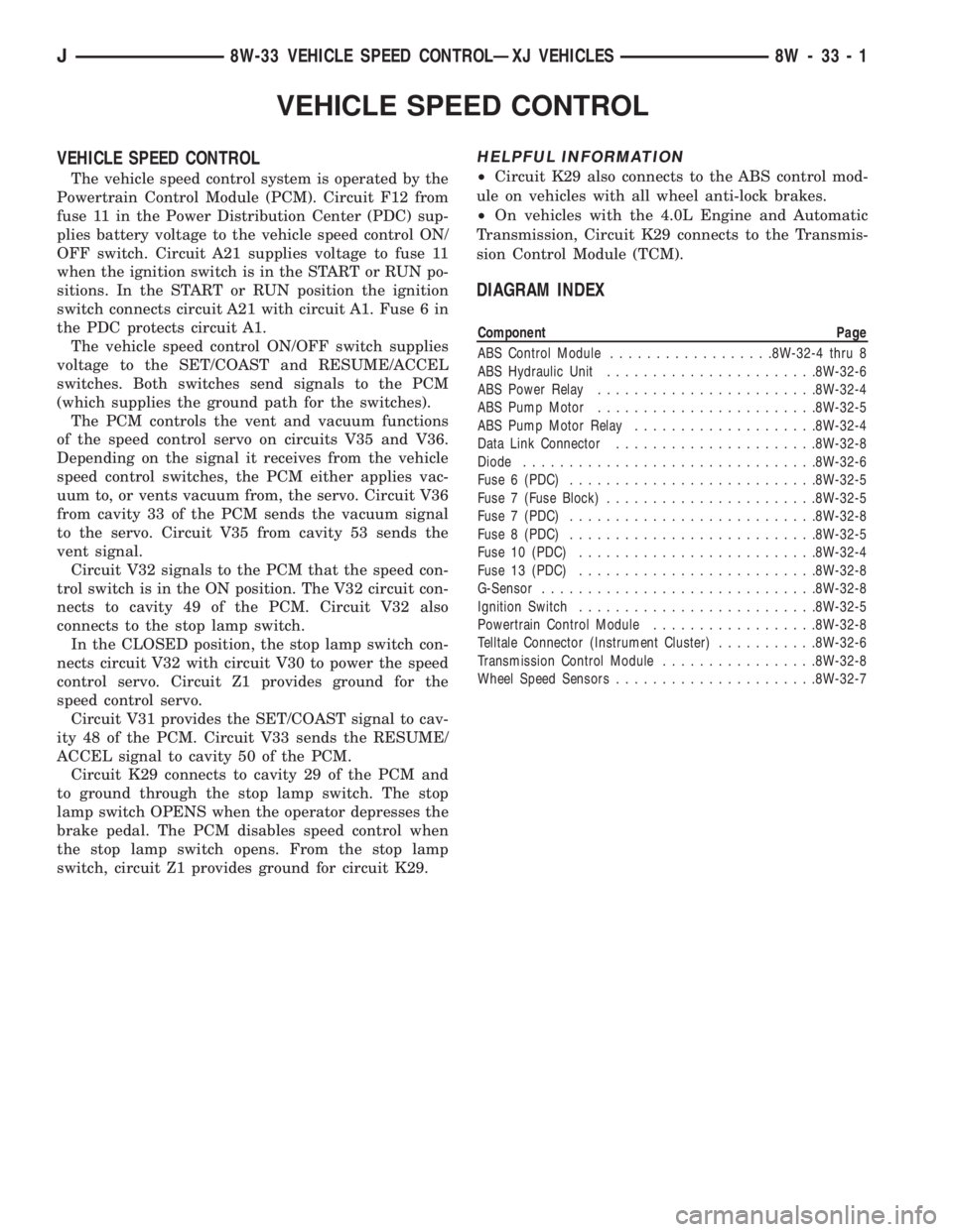
VEHICLE SPEED CONTROL
VEHICLE SPEED CONTROL
The vehicle speed control system is operated by the
Powertrain Control Module (PCM). Circuit F12 from
fuse 11 in the Power Distribution Center (PDC) sup-
plies battery voltage to the vehicle speed control ON/
OFF switch. Circuit A21 supplies voltage to fuse 11
when the ignition switch is in the START or RUN po-
sitions. In the START or RUN position the ignition
switch connects circuit A21 with circuit A1. Fuse 6 in
the PDC protects circuit A1.
The vehicle speed control ON/OFF switch supplies
voltage to the SET/COAST and RESUME/ACCEL
switches. Both switches send signals to the PCM
(which supplies the ground path for the switches).
The PCM controls the vent and vacuum functions
of the speed control servo on circuits V35 and V36.
Depending on the signal it receives from the vehicle
speed control switches, the PCM either applies vac-
uum to, or vents vacuum from, the servo. Circuit V36
from cavity 33 of the PCM sends the vacuum signal
to the servo. Circuit V35 from cavity 53 sends the
vent signal.
Circuit V32 signals to the PCM that the speed con-
trol switch is in the ON position. The V32 circuit con-
nects to cavity 49 of the PCM. Circuit V32 also
connects to the stop lamp switch.
In the CLOSED position, the stop lamp switch con-
nects circuit V32 with circuit V30 to power the speed
control servo. Circuit Z1 provides ground for the
speed control servo.
Circuit V31 provides the SET/COAST signal to cav-
ity 48 of the PCM. Circuit V33 sends the RESUME/
ACCEL signal to cavity 50 of the PCM.
Circuit K29 connects to cavity 29 of the PCM and
to ground through the stop lamp switch. The stop
lamp switch OPENS when the operator depresses the
brake pedal. The PCM disables speed control when
the stop lamp switch opens. From the stop lamp
switch, circuit Z1 provides ground for circuit K29.
HELPFUL INFORMATION
²Circuit K29 also connects to the ABS control mod-
ule on vehicles with all wheel anti-lock brakes.
²On vehicles with the 4.0L Engine and Automatic
Transmission, Circuit K29 connects to the Transmis-
sion Control Module (TCM).
DIAGRAM INDEX
Component Page
ABS Control Module..................8W-32-4 thru 8
ABS Hydraulic Unit.......................8W-32-6
ABS Power Relay........................8W-32-4
ABS Pump Motor........................8W-32-5
ABS Pump Motor Relay....................8W-32-4
Data Link Connector......................8W-32-8
Diode................................8W-32-6
Fuse 6 (PDC)...........................8W-32-5
Fuse 7 (Fuse Block).......................8W-32-5
Fuse 7 (PDC)...........................8W-32-8
Fuse 8 (PDC)...........................8W-32-5
Fuse 10 (PDC)..........................8W-32-4
Fuse 13 (PDC)..........................8W-32-8
G-Sensor..............................8W-32-8
Ignition Switch..........................8W-32-5
Powertrain Control Module..................8W-32-8
Telltale Connector (Instrument Cluster)...........8W-32-6
Transmission Control Module.................8W-32-8
Wheel Speed Sensors......................8W-32-7
J8W-33 VEHICLE SPEED CONTROLÐXJ VEHICLES 8W - 33 - 1
Page 677 of 2158
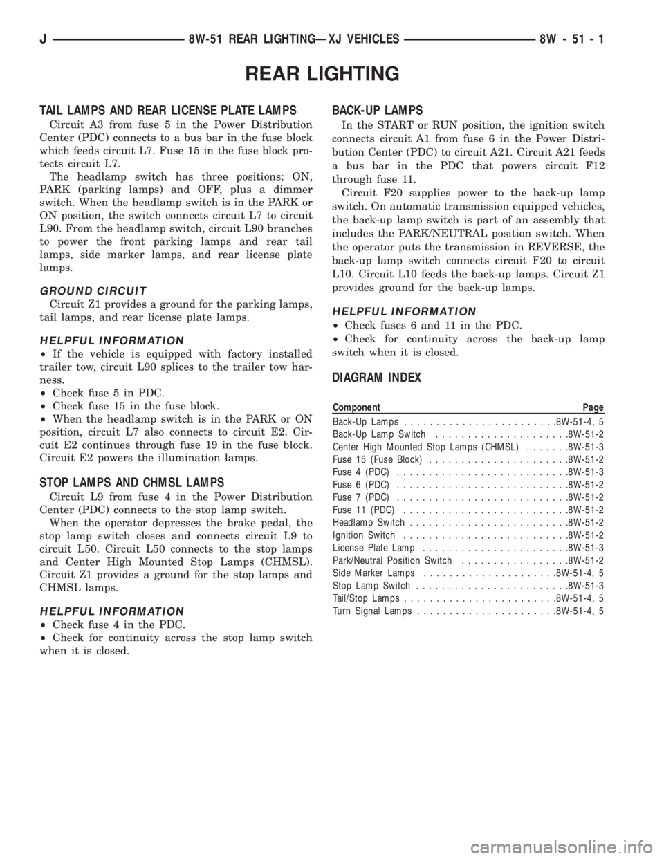
REAR LIGHTING
TAIL LAMPS AND REAR LICENSE PLATE LAMPS
Circuit A3 from fuse 5 in the Power Distribution
Center (PDC) connects to a bus bar in the fuse block
which feeds circuit L7. Fuse 15 in the fuse block pro-
tects circuit L7.
The headlamp switch has three positions: ON,
PARK (parking lamps) and OFF, plus a dimmer
switch. When the headlamp switch is in the PARK or
ON position, the switch connects circuit L7 to circuit
L90. From the headlamp switch, circuit L90 branches
to power the front parking lamps and rear tail
lamps, side marker lamps, and rear license plate
lamps.
GROUND CIRCUIT
Circuit Z1 provides a ground for the parking lamps,
tail lamps, and rear license plate lamps.
HELPFUL INFORMATION
²If the vehicle is equipped with factory installed
trailer tow, circuit L90 splices to the trailer tow har-
ness.
²Check fuse 5 in PDC.
²Check fuse 15 in the fuse block.
²When the headlamp switch is in the PARK or ON
position, circuit L7 also connects to circuit E2. Cir-
cuit E2 continues through fuse 19 in the fuse block.
Circuit E2 powers the illumination lamps.
STOP LAMPS AND CHMSL LAMPS
Circuit L9 from fuse 4 in the Power Distribution
Center (PDC) connects to the stop lamp switch.
When the operator depresses the brake pedal, the
stop lamp switch closes and connects circuit L9 to
circuit L50. Circuit L50 connects to the stop lamps
and Center High Mounted Stop Lamps (CHMSL).
Circuit Z1 provides a ground for the stop lamps and
CHMSL lamps.
HELPFUL INFORMATION
²Check fuse 4 in the PDC.
²Check for continuity across the stop lamp switch
when it is closed.
BACK-UP LAMPS
In the START or RUN position, the ignition switch
connects circuit A1 from fuse 6 in the Power Distri-
bution Center (PDC) to circuit A21. Circuit A21 feeds
a bus bar in the PDC that powers circuit F12
through fuse 11.
Circuit F20 supplies power to the back-up lamp
switch. On automatic transmission equipped vehicles,
the back-up lamp switch is part of an assembly that
includes the PARK/NEUTRAL position switch. When
the operator puts the transmission in REVERSE, the
back-up lamp switch connects circuit F20 to circuit
L10. Circuit L10 feeds the back-up lamps. Circuit Z1
provides ground for the back-up lamps.
HELPFUL INFORMATION
²Check fuses 6 and 11 in the PDC.
²Check for continuity across the back-up lamp
switch when it is closed.
DIAGRAM INDEX
Component Page
Back-Up Lamps........................8W-51-4, 5
Back-Up Lamp Switch.....................8W-51-2
Center High Mounted Stop Lamps (CHMSL).......8W-51-3
Fuse 15 (Fuse Block)......................8W-51-2
Fuse 4 (PDC)...........................8W-51-3
Fuse 6 (PDC)...........................8W-51-2
Fuse 7 (PDC)...........................8W-51-2
Fuse 11 (PDC)..........................8W-51-2
Headlamp Switch.........................8W-51-2
Ignition Switch..........................8W-51-2
License Plate Lamp.......................8W-51-3
Park/Neutral Position Switch.................8W-51-2
Side Marker Lamps.....................8W-51-4, 5
Stop Lamp Switch........................8W-51-3
Tail/Stop Lamps........................8W-51-4, 5
Turn Signal Lamps......................8W-51-4, 5
J8W-51 REAR LIGHTINGÐXJ VEHICLES 8W - 51 - 1
Page 833 of 2158
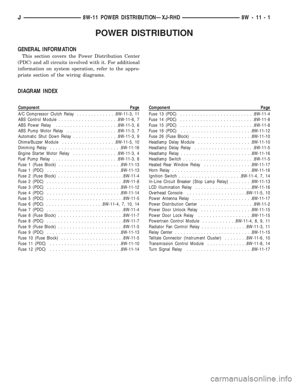
POWER DISTRIBUTION
GENERAL INFORMATION
This section covers the Power Distribution Center
(PDC) and all circuits involved with it. For additional
information on system operation, refer to the appro-
priate section of the wiring diagrams.
DIAGRAM INDEX
Component Page
A/C Compressor Clutch Relay..............8W-11-3, 11
ABS Control Module.....................8W-11-6, 7
ABS Power Relay......................8W-11-3, 6
ABS Pump Motor Relay..................8W-11-3, 7
Automatic Shut Down Relay................8W-11-3, 9
Chime/Buzzer Module...................8W-11-5, 10
Dimming Relay.........................8W-11-16
Engine Starter Motor Relay................8W-11-3, 4
Fuel Pump Relay.......................8W-11-3, 8
Fuse 1 (Fuse Block)......................8W-11-13
Fuse 1 (PDC)..........................8W-11-13
Fuse 2 (Fuse Block).......................8W-11-4
Fuse 2 (PDC)...........................8W-11-8
Fuse 3 (PDC)..........................8W-11-12
Fuse 4 (PDC)..........................8W-11-14
Fuse 5 (PDC)...........................8W-11-5
Fuse 6 (PDC)....................8W-11-4, 7, 10, 14
Fuse 7 (PDC)...........................8W-11-4
Fuse 8 (Fuse Block).......................8W-11-7
Fuse 8 (PDC)...........................8W-11-7
Fuse 9 (Fuse Block).......................8W-11-5
Fuse 9 (PDC)..........................8W-11-13
Fuse 10 (Fuse Block)......................8W-11-5
Fuse 11 (PDC).........................8W-11-10
Fuse 12 (PDC).........................8W-11-14Component Page
Fuse 13 (PDC)..........................8W-11-4
Fuse 14 (PDC)..........................8W-11-8
Fuse 15 (PDC)..........................8W-11-8
Fuse 16 (PDC).........................8W-11-12
Fuse 26 (Fuse Block).....................8W-11-10
Headlamp Delay Module...................8W-11-10
Headlamp Delay Relay.....................8W-11-5
Headlamp Relay.........................8W-11-16
Headlamp Switch.........................8W-11-5
Heated Rear Window Relay.................8W-11-17
Horn Relay............................8W-11-16
Ignition Switch......................8W-11-4, 7, 14
In-Line Circuit Breaker (Stop Lamp Relay)........8W-11-13
LCD Illumination Relay....................8W-11-16
Overhead Console.....................8W-11-5, 10
Power Antenna Relay.....................8W-11-17
Power Distribution Center...................8W-11-2
Power Door Unlock Relay..................8W-11-15
Power Door Lock Relay...................8W-11-15
Powertrain Control Module............8W-11-4, 8, 9, 11
Radiator Fan Control Relay................8W-11-3, 11
Relay Center...........................8W-11-15
Telltale Connector (Instrument Cluster)........8W-11-6, 10
Transmission Control Module..............8W-11-8, 14
Turn Signal Relay.......................8W-11-17
J8W-11 POWER DISTRIBUTIONÐXJ-RHD 8W - 11 - 1