stop start JEEP YJ 1995 Service And Owner's Guide
[x] Cancel search | Manufacturer: JEEP, Model Year: 1995, Model line: YJ, Model: JEEP YJ 1995Pages: 2158, PDF Size: 81.9 MB
Page 1406 of 2158
(8) Remove fuel pump module and O-ring seal.
Discard old O-ring and fuel pump module inlet filter.
DISASSEMBLYÐXJ MODELS
(1) Remove and discard fuel pump inlet filter.
The wire terminals to the fuel pump motor are dif-
ferent in size and cannot be connected to the wrong
terminal.
(2) Disconnect fuel pump terminal wires.
(3) Remove fuel pump outlet hose and clamp. Re-
place the hose if it shows any signs of fatigue or fail-
ure.
(4) Remove fuel pump top mounting bracket nut.
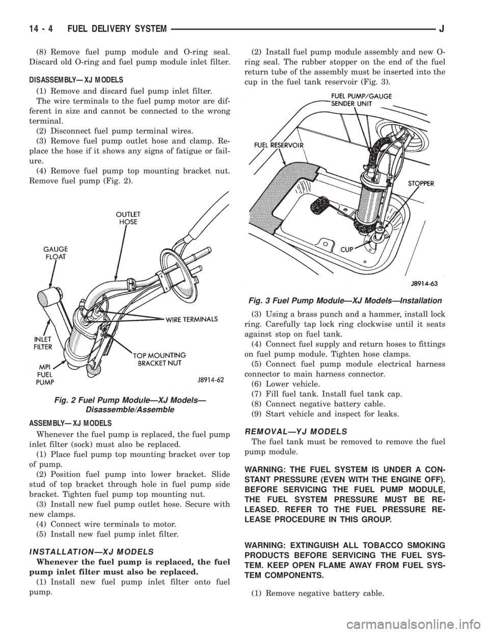
Remove fuel pump (Fig. 2).
ASSEMBLYÐXJ MODELS
Whenever the fuel pump is replaced, the fuel pump
inlet filter (sock) must also be replaced.
(1) Place fuel pump top mounting bracket over top
of pump.
(2) Position fuel pump into lower bracket. Slide
stud of top bracket through hole in fuel pump side
bracket. Tighten fuel pump top mounting nut.
(3) Install new fuel pump outlet hose. Secure with
new clamps.
(4) Connect wire terminals to motor.
(5) Install new fuel pump inlet filter.
INSTALLATIONÐXJ MODELS
Whenever the fuel pump is replaced, the fuel
pump inlet filter must also be replaced.
(1) Install new fuel pump inlet filter onto fuel
pump.(2) Install fuel pump module assembly and new O-
ring seal. The rubber stopper on the end of the fuel
return tube of the assembly must be inserted into the
cup in the fuel tank reservoir (Fig. 3).
(3) Using a brass punch and a hammer, install lock
ring. Carefully tap lock ring clockwise until it seats
against stop on fuel tank.
(4) Connect fuel supply and return hoses to fittings
on fuel pump module. Tighten hose clamps.
(5) Connect fuel pump module electrical harness
connector to main harness connector.
(6) Lower vehicle.
(7) Fill fuel tank. Install fuel tank cap.
(8) Connect negative battery cable.
(9) Start vehicle and inspect for leaks.
REMOVALÐYJ MODELS
The fuel tank must be removed to remove the fuel
pump module.
WARNING: THE FUEL SYSTEM IS UNDER A CON-
STANT PRESSURE (EVEN WITH THE ENGINE OFF).
BEFORE SERVICING THE FUEL PUMP MODULE,
THE FUEL SYSTEM PRESSURE MUST BE RE-
LEASED. REFER TO THE FUEL PRESSURE RE-
LEASE PROCEDURE IN THIS GROUP.
WARNING: EXTINGUISH ALL TOBACCO SMOKING
PRODUCTS BEFORE SERVICING THE FUEL SYS-
TEM. KEEP OPEN FLAME AWAY FROM FUEL SYS-
TEM COMPONENTS.
(1) Remove negative battery cable.
Fig. 2 Fuel Pump ModuleÐXJ ModelsÐ
Disassemble/Assemble
Fig. 3 Fuel Pump ModuleÐXJ ModelsÐInstallation
14 - 4 FUEL DELIVERY SYSTEMJ
Page 1431 of 2158
coolant temperature drops to 98ÉC (208ÉF). Refer to
Group 7, Cooling Systems for more information.
The relay is located in the power distribution cen-
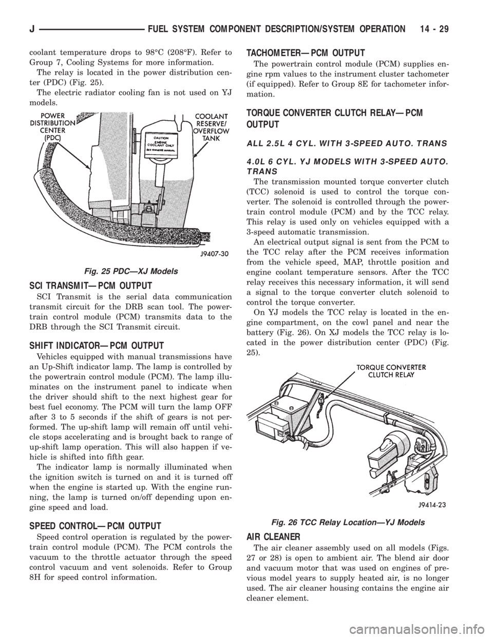
ter (PDC) (Fig. 25).
The electric radiator cooling fan is not used on YJ
models.
SCI TRANSMITÐPCM OUTPUT
SCI Transmit is the serial data communication
transmit circuit for the DRB scan tool. The power-
train control module (PCM) transmits data to the
DRB through the SCI Transmit circuit.
SHIFT INDICATORÐPCM OUTPUT
Vehicles equipped with manual transmissions have
an Up-Shift indicator lamp. The lamp is controlled by
the powertrain control module (PCM). The lamp illu-
minates on the instrument panel to indicate when
the driver should shift to the next highest gear for
best fuel economy. The PCM will turn the lamp OFF
after 3 to 5 seconds if the shift of gears is not per-
formed. The up-shift lamp will remain off until vehi-
cle stops accelerating and is brought back to range of
up-shift lamp operation. This will also happen if ve-
hicle is shifted into fifth gear.
The indicator lamp is normally illuminated when
the ignition switch is turned on and it is turned off
when the engine is started up. With the engine run-
ning, the lamp is turned on/off depending upon en-
gine speed and load.
SPEED CONTROLÐPCM OUTPUT
Speed control operation is regulated by the power-
train control module (PCM). The PCM controls the
vacuum to the throttle actuator through the speed
control vacuum and vent solenoids. Refer to Group
8H for speed control information.
TACHOMETERÐPCM OUTPUT
The powertrain control module (PCM) supplies en-
gine rpm values to the instrument cluster tachometer
(if equipped). Refer to Group 8E for tachometer infor-
mation.
TORQUE CONVERTER CLUTCH RELAYÐPCM
OUTPUT
ALL 2.5L 4 CYL. WITH 3-SPEED AUTO. TRANS
4.0L 6 CYL. YJ MODELS WITH 3-SPEED AUTO.
TRANS
The transmission mounted torque converter clutch
(TCC) solenoid is used to control the torque con-
verter. The solenoid is controlled through the power-
train control module (PCM) and by the TCC relay.
This relay is used only on vehicles equipped with a
3-speed automatic transmission.
An electrical output signal is sent from the PCM to
the TCC relay after the PCM receives information
from the vehicle speed, MAP, throttle position and
engine coolant temperature sensors. After the TCC
relay receives this necessary information, it will send
a signal to the torque converter clutch solenoid to
control the torque converter.
On YJ models the TCC relay is located in the en-
gine compartment, on the cowl panel and near the
battery (Fig. 26). On XJ models the TCC relay is lo-
cated in the power distribution center (PDC) (Fig.
25).
AIR CLEANER
The air cleaner assembly used on all models (Figs.
27 or 28) is open to ambient air. The blend air door
and vacuum motor that was used on engines of pre-
vious model years to supply heated air, is no longer
used. The air cleaner housing contains the engine air
cleaner element.
Fig. 25 PDCÐXJ Models
Fig. 26 TCC Relay LocationÐYJ Models
JFUEL SYSTEM COMPONENT DESCRIPTION/SYSTEM OPERATION 14 - 29
Page 1472 of 2158
SERVICE DIAGNOSIS
INDEX
page page
Runout.................................. 4
Unbalance............................... 3Universal Joint Angle Measurement............. 4
Vibration................................. 3
VIBRATION
Tires that are out-of-round or wheels that are un-
balanced will cause a low frequency vibration. Refer
to Group 22, Wheels and Tires for additional infor-
mation.
Brake drums that are unbalanced will cause a
harsh, low frequency vibration. Refer to Group 5,
Brakes for additional information.
Driveline vibration can also result from loose or
damaged engine mounts. Refer to Group 21, Trans-
missions for additional information.
Propeller shaft vibration will increase as the vehi-
cle speed is increased. A vibration that occurs within
a specific speed range is not caused by propeller
shaft unbalance. Defective universal joints or an in-
correct propeller shaft angle are usually the cause.
UNBALANCE
If propeller shaft unbalance is suspected, it can be
verified with the following procedure.
Removing and re-indexing the propeller shaft
180É may eliminate some vibrations.
²Clean all the foreign material from the propeller
shaft and the universal joints.²Inspect the propeller shaft for missing balance
weights, broken welds, and bent areas.If the pro-
peller shaft is bent, it must be replaced.
²Ensure the universal joints are not worn, are prop-
erly installed, and are correctly aligned with the
shaft.
²Check the universal joint clamp screws torque
(1) Raise the vehicle.
(2) Remove the wheel and tires assembly. Install
the wheel lug nuts to retain the brake drums.
(3) Mark and number the shaft six inches from the
yoke end at four positions 90É apart.
(4) Run and accelerate the vehicle until vibration
occurs. Note the intensity and speed the vibration oc-
curred. Stop the engine.
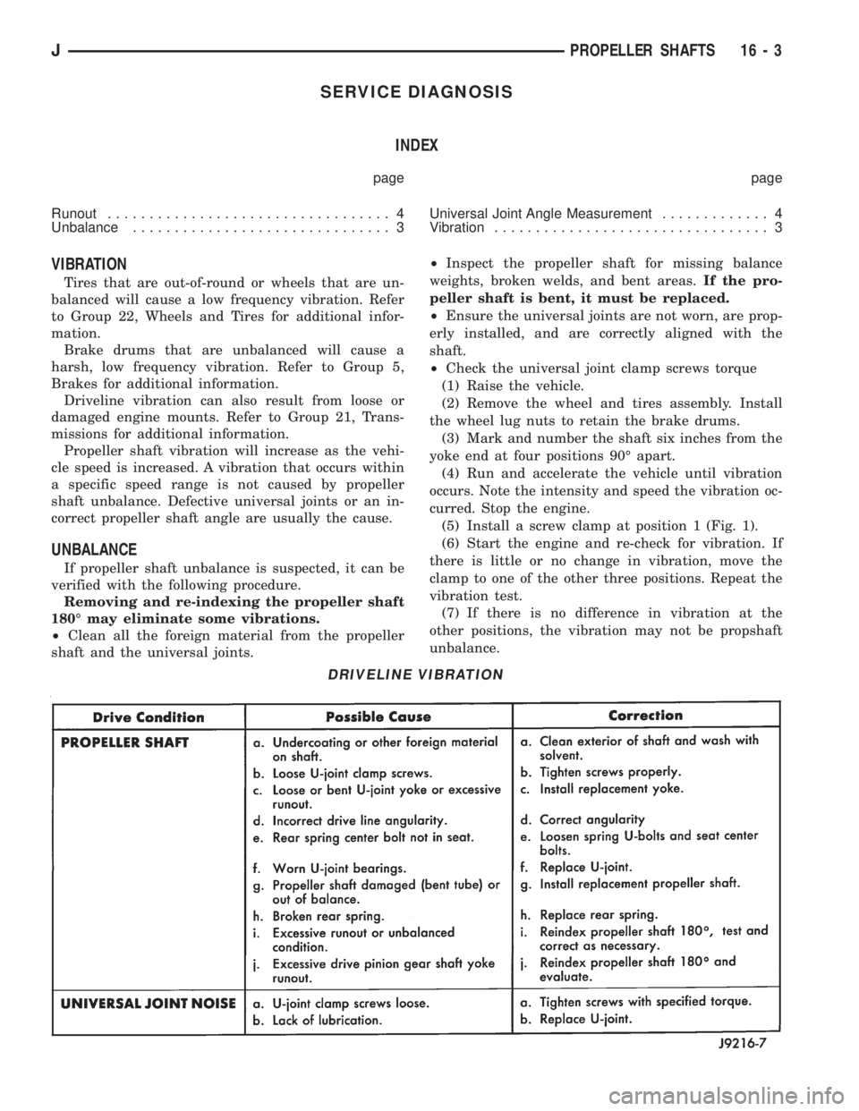
(5) Install a screw clamp at position 1 (Fig. 1).
(6) Start the engine and re-check for vibration. If
there is little or no change in vibration, move the
clamp to one of the other three positions. Repeat the
vibration test.
(7) If there is no difference in vibration at the
other positions, the vibration may not be propshaft
unbalance.
DRIVELINE VIBRATION
JPROPELLER SHAFTS 16 - 3
Page 1487 of 2158
POWER STEERING SYSTEM DIAGNOSIS
PUMP PRESSURE TEST
(1) Check belt tension and adjust as necessary.
(2) Disconnect high pressure hose at gear or pump.
Use a container for dripping fluid.
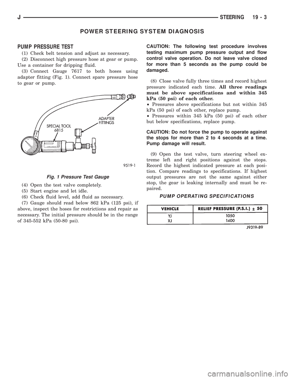
(3) Connect Gauge 7617 to both hoses using
adapter fitting (Fig. 1). Connect spare pressure hose
to gear or pump.
(4) Open the test valve completely.
(5) Start engine and let idle.
(6) Check fluid level, add fluid as necessary.
(7) Gauge should read below 862 kPa (125 psi), if
above, inspect the hoses for restrictions and repair as
necessary. The initial pressure should be in the range
of 345-552 kPa (50-80 psi).CAUTION: The following test procedure involves
testing maximum pump pressure output and flow
control valve operation. Do not leave valve closed
for more than 5 seconds as the pump could be
damaged.
(8) Close valve fully three times and record highest
pressure indicated each time.All three readings
must be above specifications and within 345
kPa (50 psi) of each other.
²Pressures above specifications but not within 345
kPa (50 psi) of each other, replace pump.
²Pressures within 345 kPa (50 psi) of each other
but below specifications, replace pump.
CAUTION: Do not force the pump to operate against
the stops for more than 2 to 4 seconds at a time.
Pump damage will result.
(9) Open the test valve, turn steering wheel ex-
treme left and right positions against the stops.
Record the highest indicated pressure at each posi-
tion. Compare readings to specifications. If highest
output pressures are not the same against either
stop, the gear is leaking internally and must be re-
paired.
Fig. 1 Pressure Test Gauge
PUMP OPERATING SPECIFICATIONS
JSTEERING 19 - 3
Page 1499 of 2158
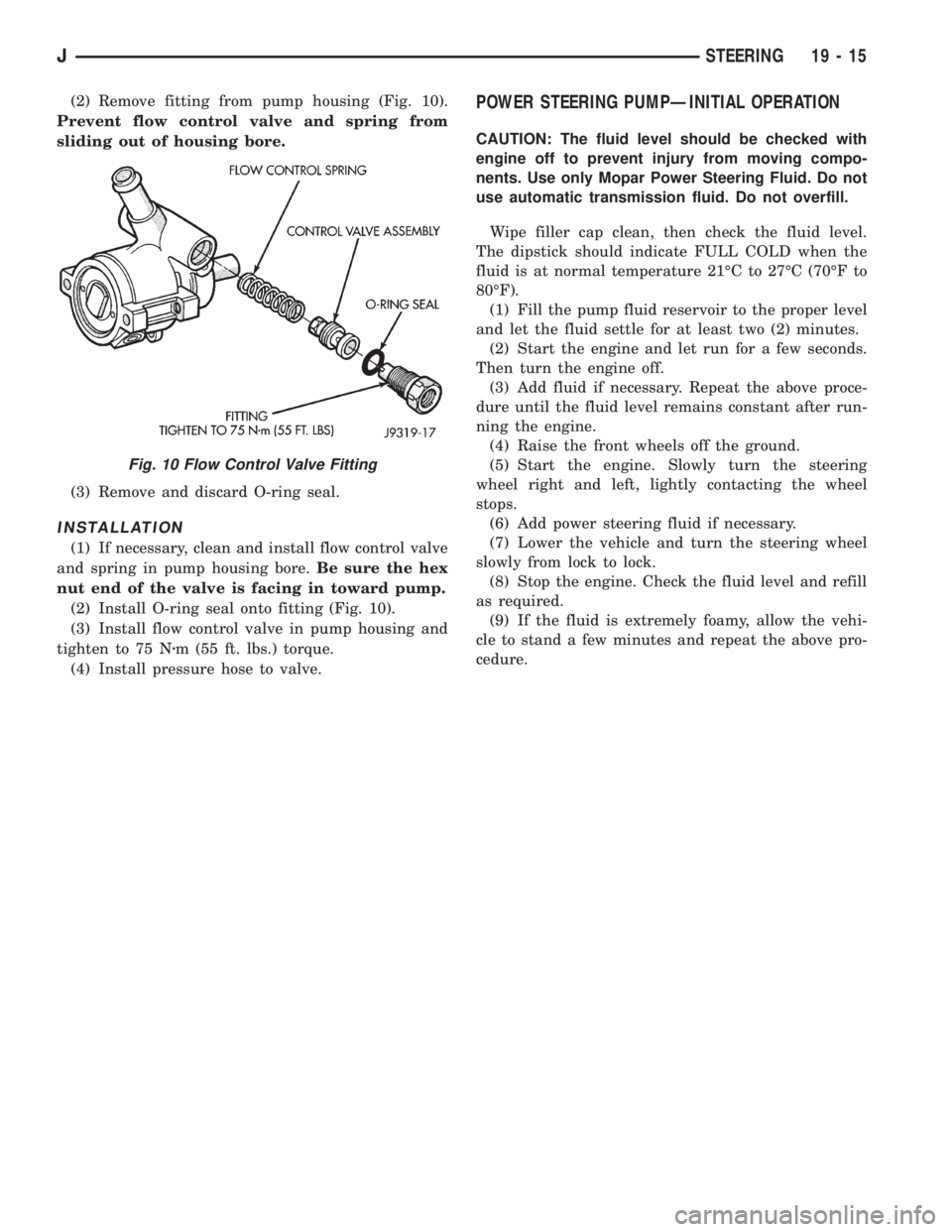
(2) Remove fitting from pump housing (Fig. 10).
Prevent flow control valve and spring from
sliding out of housing bore.
(3) Remove and discard O-ring seal.
INSTALLATION
(1) If necessary, clean and install flow control valve
and spring in pump housing bore.Be sure the hex
nut end of the valve is facing in toward pump.
(2) Install O-ring seal onto fitting (Fig. 10).
(3) Install flow control valve in pump housing and
tighten to 75 Nzm (55 ft. lbs.) torque.
(4) Install pressure hose to valve.
POWER STEERING PUMPÐINITIAL OPERATION
CAUTION: The fluid level should be checked with
engine off to prevent injury from moving compo-
nents. Use only Mopar Power Steering Fluid. Do not
use automatic transmission fluid. Do not overfill.
Wipe filler cap clean, then check the fluid level.
The dipstick should indicate FULL COLD when the
fluid is at normal temperature 21ÉC to 27ÉC (70ÉF to
80ÉF).
(1) Fill the pump fluid reservoir to the proper level
and let the fluid settle for at least two (2) minutes.
(2) Start the engine and let run for a few seconds.
Then turn the engine off.
(3) Add fluid if necessary. Repeat the above proce-
dure until the fluid level remains constant after run-
ning the engine.
(4) Raise the front wheels off the ground.
(5) Start the engine. Slowly turn the steering
wheel right and left, lightly contacting the wheel
stops.
(6) Add power steering fluid if necessary.
(7) Lower the vehicle and turn the steering wheel
slowly from lock to lock.
(8) Stop the engine. Check the fluid level and refill
as required.
(9) If the fluid is extremely foamy, allow the vehi-
cle to stand a few minutes and repeat the above pro-
cedure.
Fig. 10 Flow Control Valve Fitting
JSTEERING 19 - 15
Page 1507 of 2158
PITMAN SHAFT SEALSÐIN CAR REPLACEMENT
REMOVAL
(1) Remove pitman arm from gear. Refer to Pitman
Arm Removal in Steering Linkage.
(2) Clean exposed end of pitman shaft and hous-
ing. Use a wire brush to clean the shaft splines.
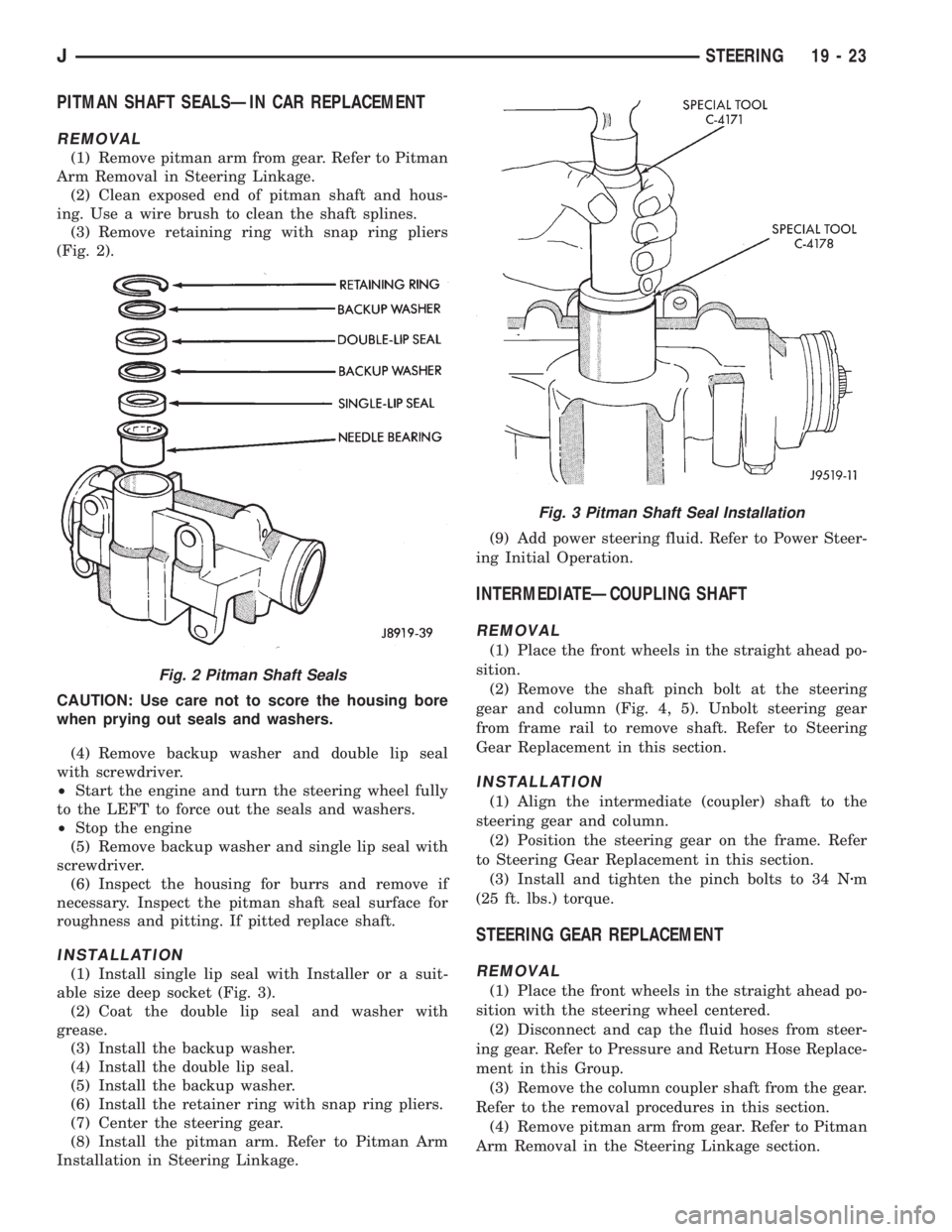
(3) Remove retaining ring with snap ring pliers
(Fig. 2).
CAUTION: Use care not to score the housing bore
when prying out seals and washers.
(4) Remove backup washer and double lip seal
with screwdriver.
²Start the engine and turn the steering wheel fully
to the LEFT to force out the seals and washers.
²Stop the engine
(5) Remove backup washer and single lip seal with
screwdriver.
(6) Inspect the housing for burrs and remove if
necessary. Inspect the pitman shaft seal surface for
roughness and pitting. If pitted replace shaft.
INSTALLATION
(1) Install single lip seal with Installer or a suit-
able size deep socket (Fig. 3).
(2) Coat the double lip seal and washer with
grease.
(3) Install the backup washer.
(4) Install the double lip seal.
(5) Install the backup washer.
(6) Install the retainer ring with snap ring pliers.
(7) Center the steering gear.
(8) Install the pitman arm. Refer to Pitman Arm
Installation in Steering Linkage.(9) Add power steering fluid. Refer to Power Steer-
ing Initial Operation.
INTERMEDIATEÐCOUPLING SHAFT
REMOVAL
(1) Place the front wheels in the straight ahead po-
sition.
(2) Remove the shaft pinch bolt at the steering
gear and column (Fig. 4, 5). Unbolt steering gear
from frame rail to remove shaft. Refer to Steering
Gear Replacement in this section.
INSTALLATION
(1) Align the intermediate (coupler) shaft to the
steering gear and column.
(2) Position the steering gear on the frame. Refer
to Steering Gear Replacement in this section.
(3) Install and tighten the pinch bolts to 34 Nzm
(25 ft. lbs.) torque.
STEERING GEAR REPLACEMENT
REMOVAL
(1) Place the front wheels in the straight ahead po-
sition with the steering wheel centered.
(2) Disconnect and cap the fluid hoses from steer-
ing gear. Refer to Pressure and Return Hose Replace-
ment in this Group.
(3) Remove the column coupler shaft from the gear.
Refer to the removal procedures in this section.
(4) Remove pitman arm from gear. Refer to Pitman
Arm Removal in the Steering Linkage section.
Fig. 2 Pitman Shaft Seals
Fig. 3 Pitman Shaft Seal Installation
JSTEERING 19 - 23
Page 1510 of 2158
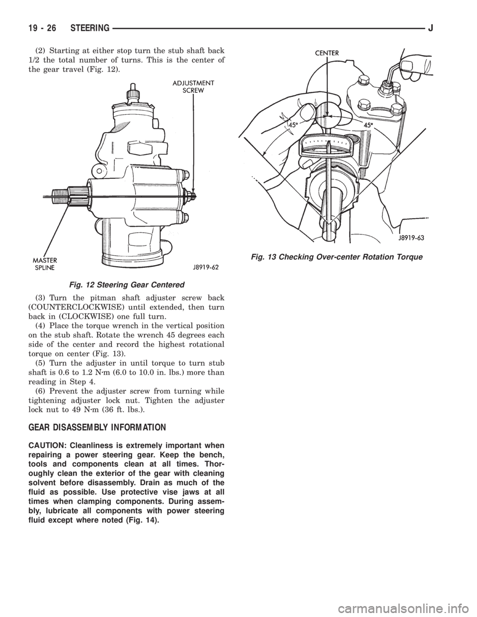
(2) Starting at either stop turn the stub shaft back
1/2 the total number of turns. This is the center of
the gear travel (Fig. 12).
(3) Turn the pitman shaft adjuster screw back
(COUNTERCLOCKWISE) until extended, then turn
back in (CLOCKWISE) one full turn.
(4) Place the torque wrench in the vertical position
on the stub shaft. Rotate the wrench 45 degrees each
side of the center and record the highest rotational
torque on center (Fig. 13).
(5) Turn the adjuster in until torque to turn stub
shaft is 0.6 to 1.2 Nzm (6.0 to 10.0 in. lbs.) more than
reading in Step 4.
(6) Prevent the adjuster screw from turning while
tightening adjuster lock nut. Tighten the adjuster
lock nut to 49 Nzm (36 ft. lbs.).
GEAR DISASSEMBLY INFORMATION
CAUTION: Cleanliness is extremely important when
repairing a power steering gear. Keep the bench,
tools and components clean at all times. Thor-
oughly clean the exterior of the gear with cleaning
solvent before disassembly. Drain as much of the
fluid as possible. Use protective vise jaws at all
times when clamping components. During assem-
bly, lubricate all components with power steering
fluid except where noted (Fig. 14).
Fig. 12 Steering Gear Centered
Fig. 13 Checking Over-center Rotation Torque
19 - 26 STEERINGJ
Page 1632 of 2158
30RH/32RH TRANSMISSION DIAGNOSIS
INDEX
page page
Air Pressure Test......................... 74
Analyzing the Road Test.................... 71
Converter Housing Leak Diagnosis............ 75
Converter Stall Test........................ 74
Diagnosis Guides and Charts................ 77
Effects of Incorrect Fluid Level............... 71
Fluid Level Check......................... 70Gearshift Cable/Linkage Adjustment........... 71
General Information....................... 70
Hydraulic Pressure Test.................... 72
Preliminary Diagnosis...................... 70
Road Test............................... 71
Transmission Throttle Valve Cable Adjustment.... 71
GENERAL INFORMATION
Automatic transmission problems are generally a
result of:
²poor engine performance
²incorrect fluid level
²incorrect throttle valve cable adjustment
²incorrect band adjustment
²incorrect hydraulic control pressure adjustments
²hydraulic component malfunctions
²mechanical component malfunctions.
Begin diagnosis by checking the easily accessible
items such as fluid level, fluid condition and control
linkage adjustment. A road test will determine if fur-
ther diagnosis is necessary.
Procedures outlined in this section should be per-
formed in the following sequence to realize the most
accurate results:
²Preliminary diagnosis
²Check fluid level and condition
²Check control linkage Adjustment
²Road test
²Stall test
²Hydraulic pressure test
²Air pressure tests
²Leak test
²Analyze test results and consult diagnosis charts
PRELIMINARY DIAGNOSIS
Two basic procedures are required. One procedure
for vehicles that are driveable and an alternate pro-
cedure for disabled vehicles (will not back up or move
forward).
Vehicle Is Driveable
(1) Check fluid level and condition.
(2) Adjust throttle cable and gearshift linkage if
complaint was based on delayed, erratic, or harsh
shifts.
(3) Road test vehicle and note transmission operat-
ing characteristics.(4) Perform stall test if complaint is based on slug-
gish, low speed acceleration or abnormal throttle
opening needed to maintain normal speeds with
properly tuned engine.
(5) Perform hydraulic pressure tests.
(6) Perform air pressure test to check clutch-band
operation.
Vehicle Is Disabled
(1) Check fluid level and condition.
(2) Check for broken, disconnected throttle linkage.
(3) Check for cracked, leaking cooler lines, or loose,
missing pressure port plugs.
(4) Raise vehicle, start engine, shift transmission
into gear and note following:
(a) If propeller shafts turn but wheels do not,
problem is with differential or axle shafts.
(b) If propeller shafts do not turn and transmis-
sion is noisy, stop engine. Remove oil pan, and
check for debris. If pan is clear, remove transmis-
sion and check for damaged drive plate, converter,
oil pump or input shaft.
(c) If propeller shafts do not turn and transmis-
sion is not noisy, perform hydraulic pressure test to
determine if problem is a hydraulic or mechanical.
FLUID LEVEL CHECK
Transmission fluid level should be checked monthly
under normal operation. If the vehicle is used for
trailer towing or similar heavy load hauling, check
fluid level and condition weekly.
Fluid level is checked with the engine running at
curb idle speed, the transmission in Neutral and the
transmission fluid at normal operating temperature.
FLUID LEVEL CHECK PROCEDURE
(1) Transmission fluid must be at normal operating
temperature for accurate fluid level check. Drive ve-
hicle if necessary to bring fluid temperature up to
normal hot operating temperature of 82ÉC (180ÉF).
(2) Position vehicle on level surface. This is ex-
tremely important for accurate fluid level check.
(3) Start and run engine at curb idle speed.
21 - 70 30RH/32RH TRANSMISSION DIAGNOSISJ
Page 1635 of 2158
Test Two-Transmission In 2 Range
This test checks pump output and pressure
regulation. Use 100 psi Test Gauge C-3292 for
this test.
(1) Connect test gauge to line pressure port (Fig.
4).
(2) Start and run engine at 1000 rpm.
(3) Move valve body selector lever one detent rear-
ward from full forward position (this is 2 range).
(4) Move transmission throttle lever from full for-
ward to full rearward position and read pressure at
both gauges.
(5) Line pressure should be 54-60 psi (372-414
kPa) with throttle lever forward and gradually in-
crease to 90-96 psi (620-662 kPa) as lever is moved
rearward.
Test Three-Transmission In Third Gear
This test checks pressure regulation and con-
dition of the front and rear clutch circuits.
Both gauges are required for this test.
(1) Connect one test gauge to line pressure port
and other gauge to front servo pressure port (Fig. 4).
Either gauge can be used at either port.
(2) Start and run engine at 1600 rpm.
(3) Move selector lever two detents rearward from
full forward position. This is D range.
(4) Read pressures on both gauges as transmission
throttle lever is moved from full forward to full rear-
ward position.
(a) Line pressure in third gear, should be 54-60
psi (372-414 kPa) with throttle lever forward and
gradually increase as lever is moved rearward.
(b) Front servo pressure in third gear, should be
within 3 psi (21 kPa) of line pressure, up to down-
shift point.
Test Four-Transmission In Reverse
This test checks pump output, pressure regu-
lation and the front clutch and rear servo cir-
cuits. Use 300 psi Pressure Test Gauge C-3293
for this test.
(1) Connect pressure test gauge to rear servo port
(Fig. 5).
(2) Start and run engine at 1600 rpm for test.
(3) Move valve body selector lever four detents
rearward from full forward position. This is Reverse
range.
(4) Move throttle lever all way forward then all the
way rearward and note gauge readings.
(5) Pressure should be 145 - 175 psi (1000-1207
kPa) with lever forward and increase to 230 - 280 psi
(1586-1931 kPa) as lever is moved rearward.
Test Five-Governor Pressure
This test checks governor operation by mea-
suring governor pressure response to changesin engine speed. It is usually not necessary to
check governor operation unless shift speeds
are incorrect or if the transmission will not
shift up or down. Use 100 psi Pressure Test
Gauge C-3292 for this test.
(1) Connect test gauge to governor pressure port
(Figs. 5 and 6).
(2) Move selector lever to D range.
(3) Apply service brakes. Start and run engine at
curb idle speed and note pressure. At idle and with
wheels stopped, pressure should be zero to 1-1/2 psi
maximum. If pressure exceeds this figure, governor
valve or weights are sticking open.
(4) Slowly increase engine speed and observe
speedometer and pressure test gauge. Governor pres-
sure should increase in proportion to vehicle speed
(approximately 1 psi for every 1 mph shown on
speedometer).
(5) Governor pressure rise should be smooth and
drop back to 0 to 1-1/2 psi when throttle is closed
and wheels are stopped.
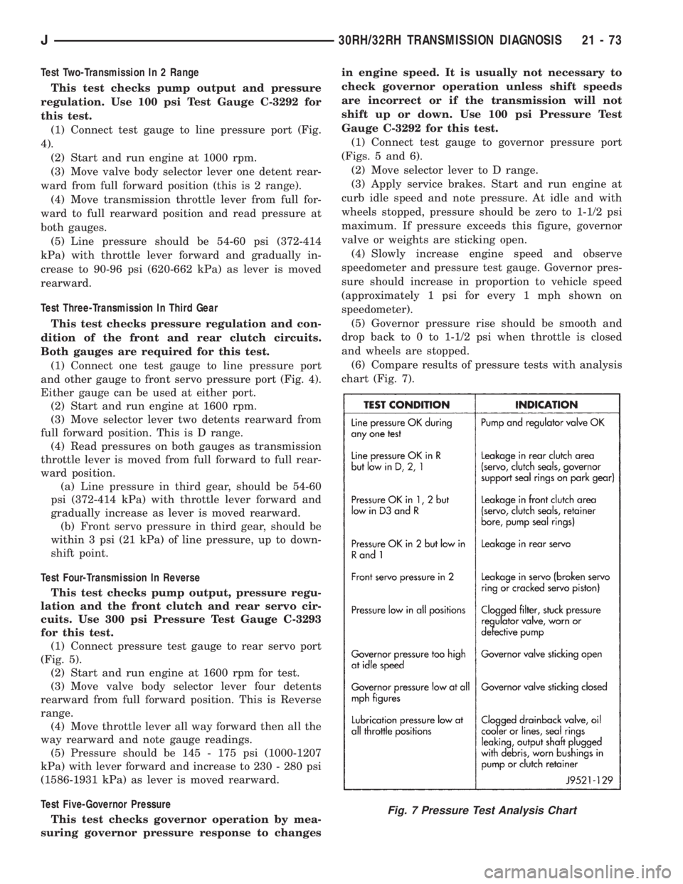
(6) Compare results of pressure tests with analysis
chart (Fig. 7).
Fig. 7 Pressure Test Analysis Chart
J30RH/32RH TRANSMISSION DIAGNOSIS 21 - 73
Page 1636 of 2158
CONVERTER STALL TEST
Stall testing involves determining maximum engine
rpm obtainable at full throttle with the rear wheels
locked and the transmission in D range. This test
checks the holding ability of the converter overrun-
ning clutch and both of the transmission clutches.
When stall testing is completed, refer to the Stall
Speed Specifications chart and Stall Speed Diagnosis
guides.
WARNING: NEVER ALLOW ANYONE TO STAND IN
FRONT OF THE VEHICLE DURING A STALL TEST.
ALWAYS BLOCK THE FRONT WHEELS AND APPLY
THE SERVICE AND PARKING BRAKES DURING
THE TEST.
STALL TEST PROCEDURE
(1) Connect tachometer to engine.
(2) Check and adjust transmission fluid level.
(3) Start and run engine until transmission fluid
reaches normal operating temperature.
(4) Block front wheels.
(5) Fully apply service and parking brakes.
(6) Open throttle completely and record maximum
engine rpm registered on tachometer. It will take
from 3 to 10 seconds to reach maximum rpm. How-
ever, once maximum rpm has been achieved,do not
hold wide open throttle for more than 5 sec-
onds.
CAUTION: Stalling the converter causes a rapid in-
crease in fluid temperature. To avoid fluid overheat-
ing, hold wide open throttle for no more than 5
seconds after reaching peak rpm. In addition, if
more than one stall test is required, run the engine
at 1000 rpm with the transmission in Neutral for at
least 20 seconds to cool the fluid.
(7) Stall speeds should be in 1700-2150 rpm range.
CAUTION: If engine exceeds 2150 rpm, release ac-
celerator pedal immediately as transmission clutch
slippage is occurring.
(8) Shift transmission into Neutral. Run engine for
20-30 seconds at 1000 rpm to cool fluid. Then stop
engine, shift transmission into Park and release
brakes.
(9) Refer to Stall Test Diagnosis.
STALL TEST DIAGNOSIS
Stall Speed Too Low
Low stall speeds with a properly tuned engine in-
dicate a torque converter overrunning clutch prob-
lem. The condition should be confirmed by road
testing prior to converter replacement.The converter overrunning clutch is slipping when
stall speeds are 250 to 350 rpm below specified min-
imum.
A converter overrunning clutch failure will result
in sluggish acceleration in all speed ranges. It will
also require greater than normal throttle opening to
maintain cruising speeds.
Stall Speed Too High
If stall speed exceeds 2150 rpm, transmission
clutch slippage is occurring.
Stall Speed Normal But Acceleration Is Sluggish
If stall speeds are within specified range but abnor-
mal throttle opening is required for acceleration, or
to maintain cruise speeds, the converter overrunning
clutch is seized. The torque converter will have to be
replaced.
Converter Noise During Test
A whining noise caused by fluid flow is normal dur-
ing a stall test. However, loud metallic noises indi-
cate a damaged converter. To confirm that noise is
originating from the converter, operate the vehicle at
light throttle in Drive and Neutral on a hoist and lis-
ten for noise from the converter housing.
AIR PRESSURE TEST
Air pressure testing can be used to check clutch
and band operation with the transmission either in
the vehicle, or on the work bench as a final check af-
ter overhaul.
Air pressure testing requires that the oil pan and
valve body be removed from the transmission.
The servo and clutch apply passages are shown in
Figure 8.
Air Test Procedure
(1) Place one or two fingers on the clutch housing
and apply air pressure through front clutch apply
passage (Fig. 8). Piston movement can be felt and a
soft thud heard as the clutch applies.
(2) Place one or two fingers on the clutch housing
and apply air pressure through rear clutch apply
passage (Fig. 8). Piston movement can be felt and a
soft thud heard as the clutch applies.
(3) Apply air pressure to the front servo apply pas-
sage. The servo rod should extend and cause the
band to tighten around the drum. Spring tension
should release the servo when air pressure is re-
moved.
(4) Apply air pressure to the rear servo apply pas-
sage. The servo rod should extend and cause the
band to tighten around the drum. Spring tension
should release the servo when air pressure is re-
moved.
21 - 74 30RH/32RH TRANSMISSION DIAGNOSISJ