stop start JEEP YJ 1995 Service And Owner's Manual
[x] Cancel search | Manufacturer: JEEP, Model Year: 1995, Model line: YJ, Model: JEEP YJ 1995Pages: 2158, PDF Size: 81.9 MB
Page 885 of 2158
VEHICLE SPEED CONTROL
VEHICLE SPEED CONTROL
The vehicle speed control system is operated by the
Powertrain Control Module (PCM).
Circuit F12 from fuse 11 in the Power Distribution
Center (PDC) supplies battery voltage to the vehicle
speed control ON/OFF switch. Circuit A21 supplies
voltage to fuse 11 when the ignition switch is in the
START or RUN positions. In the START or RUN po-
sition the ignition switch connects circuit A21 with
circuit A1. Fuse 6 in the PDC protects circuit A1.
The vehicle speed control ON/OFF switch supplies
voltage to the SET/COAST and RESUME/ACCEL
switches. Both switches send signals to the PCM
(which supplies the ground path for the switches).
The PCM controls the vent and vacuum functions
of the speed control servo on circuits V35 and V36.
Depending on the signal it receives from the vehicle
speed control switches, the PCM either applies vac-
uum to, or vents vacuum from, the servo. Circuit V36
from cavity 33 of the PCM sends the vacuum signal
to the servo. Circuit V35 from cavity 53 sends the
vent signal.
Circuit V32 signals to the PCM that the speed con-
trol switch is in the ON position. The V32 circuit con-
nects to cavity 49 of the PCM.Circuit V31 provides the SET/COAST signal to cav-
ity 48 of the PCM. Circuit V33 sends the RESUME/
ACCEL signal to cavity 50 of the PCM.
Circuit K29 connects to cavity 29 of the PCM and
to ground through the stop lamp switch. The stop
lamp switch OPENS when the operator depresses the
brake pedal. The PCM disables speed control when
the stop lamp switch opens. From the stop lamp
switch, circuit Z1 provides ground for circuit K29.
DIAGRAM INDEX
Component Page
ABS Control Module......................8W-33-2
Fuse 4 (PDC)...........................8W-33-2
Fuse 6 (PDC)...........................8W-33-2
Fuse 11 (PDC)..........................8W-33-2
Ignition Switch..........................8W-33-2
Powertrain Control Module.................8W-33-2, 3
Stop Lamp Switch........................8W-33-2
Transmission Control Module.................8W-33-2
Vehicle Speed Control Servo.................8W-33-3
Vehicle Speed Control Switch.................8W-33-3
J8W-33 VEHICLE SPEED CONTROLÐXJ-RHD 8W - 33 - 1
Page 949 of 2158
REAR LIGHTING
TAIL LAMPS AND REAR LICENSE PLATE LAMPS
Circuit A3 from fuse 5 in the Power Distribution
Center (PDC) connects to a bus bar in the fuse block
which feeds circuit L7. Fuse 9 in the fuse block pro-
tects circuit L7.
The headlamp switch has three positions: ON,
PARK (parking lamps) and OFF, plus a dimmer
switch. When the headlamp switch is in the PARK or
ON position, the switch connects circuit L7 to circuit
L90. From the headlamp switch, circuit L90 branches
to power the front parking lamps and rear tail
lamps, side marker lamps, and rear license plate
lamps.
GROUND CIRCUIT
Circuit Z1 provides a ground for the parking lamps,
tail lamps, and rear license plate lamps.
HELPFUL INFORMATION
²Check fuse 5 in PDC.
²Check fuse 9 in the fuse block.
²When the headlamp switch is in the PARK or ON
position, circuit L7 also connects to circuit E2. Cir-
cuit E2 continues through fuse 25 in the fuse block.
Circuit E2 powers the illumination lamps.
STOP LAMPS AND CHMSL LAMPS
Circuit L9 from fuse 4 in the Power Distribution
Center (PDC) connects to the stop lamp switch.
When the operator depresses the brake pedal, the
stop lamp switch closes and connects circuit L9 to
circuit L50. Circuit L50 connects to the stop lamps
and center high mounted stop lamps (CHMSL). Cir-
cuit Z1 provides a ground for the stop lamps.
HELPFUL INFORMATION
²Check fuses 13 in the PDC.
²Check for continuity across the stop lamp switch
when it is closed.
BACK-UP LAMPS
In the START or RUN position, the ignition switch
connects circuit A1 from fuse 6 in the Power Distri-
bution Center (PDC) to circuit A21. Circuit A21 feeds
a bus bar in the PDC that powers circuit F12
through fuse 11.
Circuit F12 supplies power to the back-up lamp
switch. On automatic transmission equipped vehicles,
the back-up lamp switch is part of an assembly that
includes the PARK/NEUTRAL position switch. When
the operator puts the transmission in REVERSE, the
back-up lamp switch connects circuit F12 to circuit
L10. Circuit L10 feeds the back-up lamps. Circuit Z1
provides ground for the back-up lamps.
HELPFUL INFORMATION
²Check fuses 6 and 11 in the PDC.
²Check for continuity across the back-up lamp
switch when it is closed.
DIAGRAM INDEX
Component Page
Center High Mounted Stop Lamps (CHMSL).......8W-51-3
Fuse 4 (PDC)...........................8W-51-3
Fuse 5 (PDC)...........................8W-51-2
Fuse 6 (Fuse Block).......................8W-51-2
Fuse 6 (PDC)...........................8W-51-2
Fuse 9 (Fuse Block).......................8W-51-2
Headlamp Switch.........................8W-51-2
Ignition Switch..........................8W-51-2
Left Back-Up Lamp.......................8W-51-4
Left Side Marker Lamp.....................8W-51-4
Left Tail/Stop Lamp.......................8W-51-4
Left Turn Signal Lamp.....................8W-51-4
License Plate Lamp.......................8W-51-3
Park/Neutral Position Switch.................8W-51-2
Right Back-Up Lamp......................8W-51-5
Right Side Marker Lamp....................8W-51-5
Right Tail/Stop Lamp......................8W-51-4
Right Turn Signal Lamp....................8W-51-5
Stop Lamp Switch........................8W-51-3
J8W-51 REAR LIGHTINGÐXJ-RHD 8W - 51 - 1
Page 1067 of 2158
CONNECTOR LOCATIONS
GENERAL INFORMATION
This section provides illustrations identifying com-
ponent and connector locations in the vehicle. A con-nector index is provided. Use the wiring diagrams in
each section for connector number identification. Re-
fer to the index for the proper figure number.
CONNECTOR LOCATIONS
Connector # Color Location Fig.
C101......BK ...Front Left of Engine Compartment . .2
C102......BK ...InFront of Washer Fluid Reservoir . .2
C103......BK ...Bottom of Washer Fluid Reservoir . .2
C104......BK ...Bottom of Washer Fluid Reservoir . .2
C105......BK ...TopofWasher Fluid Reservoir.....2
C106......BK ...TopofRadiator Fan Housing......2
C107......BK ...Left Fender Side Shield.........2
C108......BK ...Left Fender Side Shield.........2
C109......BK ...Near Air Cleaner..............2
C110......BK ...Left Corner of Engine Compartment .2
C111......BK ...Rear of Intake Manifold.........4
C112......BK ...OnThrottle Body.............4
C113......BK ...OnThrottle Body.............4
C114......BK ...Rear of Intake Manifold.........4
C115......GN ...Lower Right of I.P.
C116......BK ...Near ABS Control Module
C117......GN ...Center of Dash Panel...........2
C118......BK ...Injector No. 6...............4
C119......BK ...Injector No. 5...............4
C120......BK ...Injector No. 4...............4
C121......BK ...Injector No. 3...............4
C122......BK ...Injector No. 2...............4
C123......BK ...Injector No. 1...............4
C124......BK ...OnEngine, Behind Power
Steering Pump.............4
C125......BK ...OnThermostat Housing.........4
C126......BK ...OnABSControl Module.........7
C127......BK ...Near ABS Control Module........7
C128......BK ...Near Distributor..............4
C129......BK ...Near Center of Dash Panel.......3
C130......GY ...Near Center of Dash Panel.......3
C131......BK ...Near Left Kick Panel
C132......BK ...OnSteering Column...........6
C133......BK ...Near Center of Dash Panel.......3
C134......BK ...Center of Dash Panel...........3
C135......BK ...Below Brake Master Cylinder......3
C136......BK ...Right Corner of Engine Compartment .3
C137......BK ...Right Side of Hood............3
C138......BK ...Near ABS Control Module
C139......BK ...Near ABS Control Module........7
C140......GY ...Near ABS Control Module........7
C141......GN ...Near ABS Control Module........7
C142......BK ...Right Fender Side Shield........3
C143......BK ...Right Fender Side Shield........3
C144......BK ...Right Fender Side Shield........3
C145......BK ...Right Fender Side Shield........3
C146......BK ...Below Battery................3
C147......BK ...Rear of Battery...............5
C148......BK ...AtStarter Motor..............4
C149......BK ...Right Side of Engine Near Distributor .4
C150......BK ...Rear of Generator.............4
C151......BK ...Rear of Generator.............5Connector # Color Location Fig.
C152......BK ...Behind Lens................1
C153......BK ...Left Rear of Radiator Closure Panel .1
C154......BK ...Behind Lens................1
C155......BK ...Behind Lens................1
C156......BK ...Behind Lens................1
C157......BK ...Center of Grille Opening.........1
C158......BK ...Center of Grille Opening.........1
C159......BK ...Behind Lens................1
C160......BK ...Behind Lens................1
C201......GY ...Center Bottom of I.P............8
C202......WT ...Center Bottom of I.P............8
C203......BK ...Behind Right Kick Panel........12
C204......BK ...Right Side of I.P.
C205......BK ...Left Rear of I.P...............8
C206......BK ...Left Rear of I.P...............8
C207......BK ...Near Right Kick Panel..........7
C208......GN ...Near Right Kick Panel..........7
C209......RD ...Behind Right Kick Panel........12
C210......BK ...Behind Fender Side Shield
C211......BK ...Near Right Kick Panel..........7
C212......BK ...Near Right Kick Panel
C213......BK ...Rear of Headlamp Switch.......10
C214......BK ...Rear of I.P., Right of Steering
Column..................9
C215......BK ...Rear of I.P., Right of Steering
Column..................9
C216......BK ...Rear of I.P., Right of Steering
Column.................9
C217......RD ...Rear of I.P., Right of Steering
Column..................9
C218......BK ...Below Stop Lamp Switch........7
C219......BK ...Rear of I.P., Right of Steering
Column.................9
C220......NAT ..Rear of I.P. Cluster...........10
C221......BK ...Rear of I.P. Cluster...........10
C222......NAT ..Rear of I.P., Left of Steering Column .9
C223......BK ...Rear of I.P., Left of Steering Column .9
C224......BK ...Rear of I.P., Left of Steering Column .9
C225......BK ...Rear of I.P., Left of Steering Column .9
C226......BK ...OnSteering Column...........6
C227......BK ...Near ABS Control Module........7
C228......WT ...Center of I.P.
C229......BK ...Center of I.P.
C230......BK ...OnSteering Column...........6
C231......BK ...OnSteering Column...........6
C232......BK ...OnSteering Column...........6
C233......BK ...Center Bottom of I.P............8
C234......BK ...Rear of I.P., Above Ash Receiver . . .8
C235......BK ...Rear of Radio...............9
C236......BR ...Rear of A/C-Heater Controls.....10
C237......BK ...Center Bottom of I.P............8
C238......BK ...Near ABS Control Module........7
J8W-90 CONNECTOR LOCATIONSÐXJ-RHD 8W - 90 - 1
Page 1174 of 2158
INTERIOR LIGHTING
INDEX
page page
Accessory Lamp and Heater Control Panel Lamp . . 1
Combination Buzzer........................ 1
Courtesy Lamps and Dome Lamps............. 1
Diagram Index............................ 2General Information........................ 1
Transmission Range Lamp................... 1
Underhood Lamp.......................... 1
GENERAL INFORMATION
Circuit M1 supplies power to the underhood lamp,
dome lamp, right courtesy lamp and left courtesy
lamp. Fuse 12 in the Power Distribution Center
(PDC) protects circuit M1. Circuit A4 from fuse 8 in
the PDC supplies voltage to fuse 12 and circuit M1.
Fuse 12 is referred to as the Ignition Off Draw (IOD)
fuse.
COURTESY LAMPS AND DOME LAMPS
Circuit M1 supplies battery voltage to the dome
lamps and the right and left courtesy lamps. Circuit
M2 provides ground for the lamps through either the
case grounded door jamb switches or through the
dimmer switch to circuit Z1.
In the ON position, the dimmer switch connects
circuit M2 to ground on circuit Z1. When a door
opens, the case grounded door jamb switch closes and
provides ground for the lamps on circuit M2.
HELPFUL INFORMATION
²Circuit M1 also supplies voltage for radio memory,
underhood lamp and the ABS data link connector.
UNDERHOOD LAMP
Circuit M1 supplies battery voltage for the under-
hood lamp. A mercury switch in series after the lamp
connects the lamp to ground on circuit Z1. When the
hood is raised, mercury inside the switch moves to a
position where it connects circuit M1 to circuit Z1, il-
luminating the lamp. The underhood lamp is wired
in parallel with other components on circuit M1.
ACCESSORY LAMP AND HEATER CONTROL PANEL
LAMP
Circuit E1 from the dimmer switch supplies bat-
tery voltage to fuse 10 in the fuse block when the
dimmer switch is in the LOW or ON position. Fuse
10 protects circuit E2 which supplies power to the
heater control panel lamp and the accessory lamp.
Circuit Z1 provides ground for each lamp.
TRANSMISSION RANGE LAMP
Circuit E1 from the dimmer switch supplies bat-
tery voltage to fuse 10 in the fuse block when thedimmer switch is in the LOW or ON positions. Fuse
10 protects circuit E2 which supplies power to the
transmission range lamp. The lamp is case grounded.
COMBINATION BUZZER
The combination buzzer module sounds an audible
warning tone. The tone sounds for seat belt warning
and when the key is in the ignition switch while the
drivers door is open. The tone also sounds when the
ignition switch is in the ON position while the driv-
ers side seat belt is not buckled. Refer to Group 8U
for buzzer operation.
Fuses 3 and 9 in the fuse block protect the combi-
nation buzzer. Fuse 3 powers circuit F32 which con-
nects to the buzzer. Circuit A6 from fuse 3 in the
Power Distribution Center (PDC) supplies power to
the fuse block for circuit F32.
Circuit G5 from fuse 9 also provides voltage to the
combination buzzer when the ignition switch is in
the START or RUN position. The ignition switch con-
nects circuit A1 from fuse 4 in the PDC to circuit
A21. Circuit A21 connects to the fuse block.
When the key-in switch closes, it connects circuit
G26 to circuit G16. Circuit G16 connects to the driv-
ers side door jamb switch. When the drivers side door
is open and the key-in switch is closed, the case
grounded door jamb switch closes and supplies
ground for the buzzer. Circuit G26 from the combina-
tion buzzer connects to the key-in switch.
Circuit G13 form the buzzer powers the seat belt
warning lamp in the instrument cluster. Circuit Z1
at the instrument cluster provides ground for the
lamp.
Circuit G10 from the buzzer connects to the seat
belt switch. When the seat belt is unlatched, the seat
belt switch closes providing ground on circuit Z1.
Circuit Z1 also grounds the combination buzzer
module.
HELPFUL INFORMATION
²Circuit F32 also powers the stop lamp switch.
²Circuit G5 also provides power for the instrument
cluster gauges and warning lamps, heated rear win-
dow relay and A/C compressor clutch relay. On Cana-
J8W-44 INTERIOR LIGHTINGÐYJ VEHICLES 8W - 44 - 1
Page 1191 of 2158
When the park lamp relay energizes, the relay con-
tacts close and connect circuit F81 from fuse 6 in the
fuse block to circuit L36. Circuit L36 connects to the
contact side of the high beam relay. The contacts in
the high beam relay are normally closed. Battery
voltage flows through high beam relay to the fog
lamps on circuit L39. Circuit L39 also splices to the
lamp in the fog lamp switch.
Circuit L3 from the dimmer switch provides power
for the high beams of the headlamps and connects to
Circuit G34. Circuit G34 powers the coil side of the
high beam relay. Circuit Z1 provides ground for the
coil. When the operator selects high beam operation
or flashes the optical horn, circuit G34 energizes the
high beam relay. When energized, the normally
closed contacts in the relay open, shutting off battery
voltage to the fog lamps on circuit L39.
HELPFUL INFORMATION
²Circuit A6 from fuse 3 in the PDC supplies voltage
to the fuse block for fuses in cavities 3 and 6. Fuse 6
in the fuse block protects circuit F81 which powers
the contact side of the park lamp relay.
²In the high beam position, the dimmer switch con-
nects circuit L20 from the headlamp switch to circuit
L3. The headlamp switch connects circuit A3 from
fuse 7 in the PDC with circuit L20. Circuits A3 and
L20 are HOT at all times.
DAYTIME RUNNING LAMP (DRL) MODULEÐ
CANADIAN VEHICLES ONLY
On Canadian vehicles, the low-beam headlamps op-
erate when the ignition switch is in the RUN position
and the headlamp switch is OFF.
When the ignition switch is in the START or RUN
positions, circuit A1 from fuse 4 in the Power Distri-
bution Center (PDC) connects to circuit A21. Circuit
A21 supplies voltage to circuit G5 through fuse 9 in
the fuse block. Circuit G5 splices to supply battery
voltage to the DRL module.
Circuit L20 from the headlamp switch connects to
the DRL module. Circuit L20 is HOT at all times.
The DRL module receives the vehicle speed sensor
input from circuit G7. Circuit G34 from the DRLmodule provides power for the high beam indicator
lamp in the instrument cluster.
Circuit L4 feeds the low beams of the headlamps.
When the headlamp switch is in the OFF position,
the DRL module powers the left and right headlamps
on circuit L4. When the headlamps are ON, the dim-
mer switch powers the low beams on circuit L4.
Circuit L3 feeds the high beams of the headlamps.
When the operator flashes the high beams with the
turn signal stalk, the DRL senses voltage on circuit
L3. When it senses voltage on circuit L3, the DRL
module stops supplying power to the low beams on
circuit L4.
Circuit Z1 provides ground for the DRL module.
Circuit Z1 terminates at the radiator left side sup-
port.
DIAGRAM INDEX
Component Page
Daytime Running Lamp (DRL) Module. . . .8W-50-3, 7, 9, 11
Fog Lamps.............................8W-50-9
Fog Lamp Switch........................8W-50-9
Fuse 3 (PDC)...........................8W-50-3
Fuse 4 (PDC)..........................8W-50-10
Fuse 6 (Fuse Block).......................8W-50-8
Fuse 7 (PDC)........................8W-50-3, 10
Fuse 8 (Fuse Block).......................8W-50-3
Fuse 9 (Fuse Block)......................8W-50-10
Headlamp Switch....................8W-50-3, 8, 10
Headlamp Dimmer Switch.................8W-50-3, 8
High Beam Relay.........................8W-50-9
Ignition Switch.........................8W-50-10
Instrument Cluster..................8W-50-3 thru 10
Left Headlamp.........................8W-50-4, 6
Left Park, Turn Signal Lamp...............8W-50-4, 6
Left Side Marker Lamp...................8W-50-4, 6
Park Lamp Relay.........................8W-50-8
Powertrain Control Module..................8W-50-11
Right Headlamp........................8W-50-5, 7
Right Park, Turn Signal Lamp..............8W-50-5, 7
Right Side Marker Lamp..................8W-50-5, 7
8W - 50 - 2 8W-50 FRONT LIGHTINGÐYJ VEHICLESJ
Page 1202 of 2158
REAR LIGHTING
TAIL LAMPS AND LICENSE PLATE LAMPS
Circuit A6 in the Power Distribution Center (PDC)
connects to a bus bar in the fuse block. The fuse
block bus bar powers circuit F33. Circuit F33 con-
nects to the headlamp switch. Fuse 3 in the PDC
protects circuit A3. Fuse 8 in the fuse block protects
circuit F33.
The headlamp switch has three positions: ON,
PARK (parking lamps) and OFF, plus a dimmer
switch. When the headlamp switch is in the PARK or
ON position, the switch connects circuit F33 to cir-
cuit L7. From the headlamp switch, circuit L7
branches to power the front parking lamps and rear
tail and license plate lamps. The lamps are case
grounded.
HELPFUL INFORMATION
²If the vehicle is equipped with factory installed fog
lamps, circuit L7 splices to feed the park lamp relay.
²Jumper harnesses connect the tail, stop, turn sig-
nal lamp to the body harness.
²Check fuse 3 in the PDC.
²Check fuse 8 in the fuse block.
²Circuit L7 also feeds the radio, if equipped.
STOP LAMPS AND CHMSL LAMPS
Circuit A6 from fuse 3 in the Power Distribution
Center (PDC) supplies voltage to the fuse block bus
bar. The bus bar powers circuit F32 through fuse 3 in
the fuse block. Circuit F32 connects to the stop lamp
switch.
When the operator depresses the brake pedal, the
stop lamp switch closes, and connects circuit F32 to
circuit L50. Circuit L50 connects to the CHMSL
lamps and turn signal/hazard flasher. Circuit Z1 pro-
vides ground for the CHMSL lamps. The turn signal/
hazard flasher supplies current to the L62 and L63
circuits. Circuit L62 powers the right stop lamp. Cir-
cuit L63 powers the left stop lamp. The stop lamps
are case grounded.
HELPFUL INFORMATION
²Circuits L50 and Z1 pass through contacts in the
rear door before reaching the CHMSL lamps.
²Check fuse 3 in the PDC.²Check fuse 3 in the fuse block.
²Check for continuity across the stop lamp switch
when it is closed.
²If the vehicle is equipped with anti-lock brakes,
circuit L50 connects to the ABS module.
BACK-UP LAMPS
In the START or RUN position, the ignition switch
connects circuit A1 from fuse 4 in the Power Distri-
bution Center (PDC) to circuit A21. Circuit A21 feeds
a bus bar in the fuse block that powers circuit G5
through fuse 9.
Circuit G5 splices to supply power to the back-up
lamp switch. On automatic transmission vehicles, the
back-up lamp switch is part of an assembly that in-
cludes the PARK/NEUTRAL position switch.
When the operator puts the transmission in Re-
verse, the back-up lamp switch connects circuit G5 to
circuit L1. Circuit L1 feeds the case grounded
back-up lamps.
HELPFUL INFORMATION
²Check fuse 4 in the PDC.
²Check fuse 9 in the fuse block.
²Check for continuity across the back-up lamp
switch when it is closed.
DIAGRAM INDEX
Component Page
ABS Control Module......................8W-51-3
Back-Up Lamps..........................8W-51-4
Back-Up Lamp Switch.....................8W-51-2
Center High Mounted Stop Lamps (CHMSL).......8W-51-3
Fuse 3 (Fuse Block).......................8W-51-2
Fuse 3 (PDC)...........................8W-51-2
Fuse 4 (PDC)...........................8W-51-2
Fuse 9 (Fuse Block).......................8W-51-2
Fuse 8 (Fuse Block).......................8W-51-2
Headlamp Switch.........................8W-51-2
Ignition Switch..........................8W-51-2
Powertrain Control Module..................8W-51-3
Stop Lamp Switch........................8W-51-3
Tail, Stop, and Turn Signal Lamps.............8W-51-4
J8W-51 REAR LIGHTINGÐYJ VEHICLES 8W - 51 - 1
Page 1285 of 2158
CYLINDER COMBUSTION PRESSURE LEAKAGE
TEST
The combustion pressure leakage test provides an
accurate means for determining engine condition.
Combustion pressure leakage testing will detect:
²Exhaust and intake valve leaks (improper seat-
ing).
²Leaks between adjacent cylinders or into water
jacket.
²Any causes for combustion/compression pressure
loss.
WARNING: DO NOT REMOVE THE RADIATOR CAP
WITH THE SYSTEM HOT AND UNDER PRESSURE
BECAUSE SERIOUS BURNS FROM COOLANT CAN
OCCUR.
Check the coolant level and fill as required. DO
NOT install the radiator cap.
Start and operate the engine until it attains nor-
mal operating temperature, then turn the engine
OFF.
Remove the spark plugs.
Remove the oil filler cap.
Remove the air cleaner.
Calibrate the tester according to the manufactur-
er's instructions. The shop air source for testing
should maintain 483 kPa (70 psi) minimum, 1 379
kPa (200 psi) maximum and 552 kPa (80 psi) recom-
mended.
Perform the test procedures on each cylinder ac-
cording to the tester manufacturer's instructions.
While testing, listen for pressurized air escaping
through the throttle body, tailpipe and oil filler cap
opening. Check for bubbles in the radiator coolant.
All gauge pressure indications should be equal,
with no more than 25% leakage.
FOR EXAMPLE:At 552 kPa (80 psi) input pres-
sure, a minimum of 414 kPa (60 psi) should be main-
tained in the cylinder.
Refer to the Cylinder Combustion Pressure Leak-
age Test Diagnosis chart.
INSPECTION (ENGINE OIL LEAKS IN GENERAL)
Begin with a through visual inspection of the en-
gine, particularly at the area of the suspected leak. If
an oil leak source is not readily identifiable, the fol-
lowing steps should be followed:
(1) Do not clean or degrease the engine at this
time because some solvents may cause rubber to
swell, temporarily stopping the leak.
(2) Add an oil soluble dye (use as recommended by
manufacturer). Start the engine and let idle for ap-
proximately 15 minutes. Check the oil dipstick to
make sure the dye is thoroughly mixed as indicated
with a bright yellow color under a black light.(3) Using a black light, inspect the entire engine
for fluorescent dye, particularly at the suspected area
of oil leak. If the oil leak is found and identified, re-
pair per service manual instructions.
(4) If dye is not observed, drive the vehicle at var-
ious speeds for approximately 24km (15 miles), and
repeat step (3).
If the oil leak source is not positively identi-
fied at this time, proceed with the air leak detec-
tion test method as follows:
(1) Disconnect the breather cap to air cleaner hose
at the breather cap end. Cap or plug breather cap
nipple.
(2) Remove the PCV valve from the cylinder head
cover. Cap or plug the PCV valve grommet.
(3) Attach an air hose with pressure gauge and
regulator to the dipstick tube.
CAUTION: Do not subject the engine assembly to
more than 20.6 kpa (3 PSI) of test pressure.
(4) Gradually apply air pressure from 1 psi to 2.5
psi maximum while applying soapy water at the sus-
pected source. Adjust the regulator to the suitable
test pressure that provide the best bubbles which
will pinpoint the leak source. If the oil leak is de-
tected and identified, repair per service manual pro-
cedures.
(5) If the leakage occurs at the rear oil seal area,
refer to the section, Inspection for Rear Seal Area
Leak.
(6) If no leaks are detected, turn off the air supply
and remove the air hose and all plugs and caps. In-
stall the PCV valve and breather cap hose. Proceed
to step 7.
(7) Clean the oil off the suspect oil leak area using
a suitable solvent. Drive the vehicle at various
speeds approximately 24 km (15 miles). Inspect the
engine for signs of an oil leak by using a black light.
INSPECTION FOR REAR SEAL AREA LEAKS
Since it is sometimes difficult to determine the
source of an oil leak in the rear seal area of the en-
gine, a more involved inspection is necessary. The fol-
lowing steps should be followed to help pinpoint the
source of the leak.
If the leakage occurs at the crankshaft rear oil seal
area:
(1) Disconnect the battery.
(2) Raise the vehicle.
(3) Remove torque converter or clutch housing
cover and inspect rear of block for evidence of oil.
Use a black light to check for the oil leak:
(a) Circular spray pattern generally indicates
seal leakage or crankshaft damage.
(b) Where leakage tends to run straight down,
possible causes are a porous block, distributor seal,
camshaft bore cup plugs oil galley pipe plugs, oil
9 - 6 ENGINESJ
Page 1299 of 2158
(a) Align the transmission torque converter hous-
ing with the engine.
(b) Loosely install the converter housing lower
bolts and install the next higher bolt and nut on
each side.
(c) Tighten all 4 bolts finger-tight.
(5) Install the engine support cushions (if re-
moved).
(6) Lower the engine and engine support cushions
onto the engine compartment brackets.
(7) Remove the engine lifting device.
(8) Raise the vehicle.
(9) If equipped with an automatic transmission:
(a) Install the converter-to-drive plate bolts. En-
sure the installation reference marks are aligned.
Tighten the bolts to 54 Nzm (40 ft. lbs.) torque.
(b) Install the converter-housing access cover.
(c) Install the exhaust pipe support.
(10) Install the remaining converter or flywheel
housing bolts.
(11) Install the starter motor and connect the ca-
ble. Tighten the bolts to 45 Nzm (33 ft. lbs.) torque.
(12) Tighten the engine support cushing through-
bolt nuts.
(13) Install the remaining flywheel and converter
housing bolts. Tighten the bolts to 38 Nzm (28 ft. lbs.)
torque.
(14) Connect the exhaust pipe to the manifold.
(15) Install the oil filter.
(16) Lower the vehicle.
(17) Connect the coolant hoses and tighten the
clamps.
(18) If equipped with power steering:
(a) Remove the protective caps
(b) Connect the hoses to the fittings at the steer-
ing gear. Tighten the nut to 52 Nzm (38 ft. lbs.)
torque.
(c) Fill the pump reservoir with fluid.
(19) Remove the pulley-to-water pump flange
alignment capscrew and install the fan and spacer or
Tempatrol fan assembly.
(20) Install the fan shroud and radiator and con-
denser (if equipped with air conditioning).
(21) Connect the radiator hoses.
(22) Connect the automatic transmission fluid
cooler pipes, if equipped.
(23) Connect the oxygen sensor wire connector.
(24) Connect the throttle valve rod and retainer.
Connect the throttle cable and install the rod. Install
the throttle valve rod spring.
(25) Connect the speed control cable, if equipped.
(26) Connect the fuel supply and return lines to
the throttle body.
(27) Connect all the vacuum hoses and wire con-
nectors.
(28) Connect the service valves to the A/C compres-
sor ports, if equipped with air conditioning.(29) Fill the power steering reservoir.
(30) Connect the battery cables.
(31) Install the hood.
(32) Install the air cleaner.
(33) Start the engine and inspect for leaks.
(34) Fill the cooling system.
(35) Stop the engine and check the fluid levels.
Add fluid, as required.
ENGINE ASSEMBLYÐYJ VEHICLES
REMOVAL
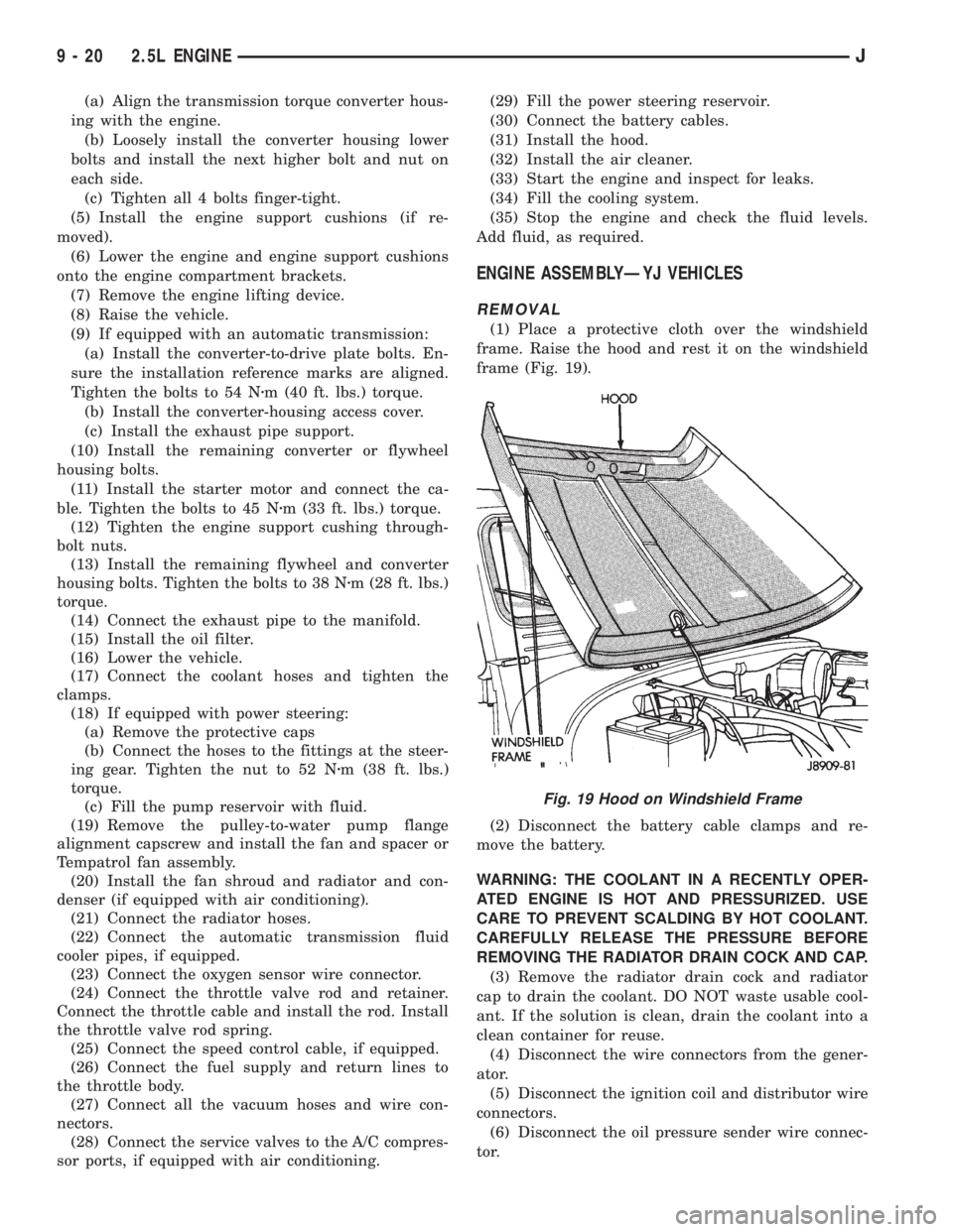
(1) Place a protective cloth over the windshield
frame. Raise the hood and rest it on the windshield
frame (Fig. 19).
(2) Disconnect the battery cable clamps and re-
move the battery.
WARNING: THE COOLANT IN A RECENTLY OPER-
ATED ENGINE IS HOT AND PRESSURIZED. USE
CARE TO PREVENT SCALDING BY HOT COOLANT.
CAREFULLY RELEASE THE PRESSURE BEFORE
REMOVING THE RADIATOR DRAIN COCK AND CAP.
(3) Remove the radiator drain cock and radiator
cap to drain the coolant. DO NOT waste usable cool-
ant. If the solution is clean, drain the coolant into a
clean container for reuse.
(4) Disconnect the wire connectors from the gener-
ator.
(5) Disconnect the ignition coil and distributor wire
connectors.
(6) Disconnect the oil pressure sender wire connec-
tor.
Fig. 19 Hood on Windshield Frame
9 - 20 2.5L ENGINEJ
Page 1301 of 2158
(14) Install the remaining flywheel housing bolts.
Tighten the bolts to 38 Nzm (28 ft. lbs.) torque.
(15) Install the starter motor and connect the ca-
ble. Tighten the bolts to 45 Nzm (33 ft. lbs.) torque.
(16) Install the oil filter.
(17) Lower the vehicle.
(18) Connect the coolant hoses and tighten the
clamps.
(19) If equipped with power steering:
(a) Remove the protective caps
(b) Connect the hoses to the fittings at the steer-
ing gear. Tighten the nut to 52 Nzm (38 ft. lbs.)
torque.
(c) Fill the pump reservoir with fluid.
(20) Remove the pulley-to-water pump flange
alignment capscrew and install the fan and spacer or
Tempatrol fan assembly.
(21) Tighten the serpentine drive belt according to
the specifications listed in Group 7, Cooling System.
(22) Install the fan shroud and radiator.
(23) Connect the radiator hoses.
(24) Connect the heater hoses.
(25) Connect the throttle valve rod and retainer.
(26) Connect the throttle cable and install the rod.
(27) Install the throttle valve rod spring.
(28) Connect the speed control cable, if equipped.
(29) Connect the oxygen sensor wire connector.
(30) Install the vacuum hose and check valve on
the brake booster.
(31) Connect the coolant temperature sensor wire
connector.
(32) Connect the idle speed actuator wire connec-
tor.
(33) Connect the fuel inlet and return hoses at the
fuel rail. Verify that the quick-connect fitting assem-
bly fits securely over the fuel lines by giving the fuel
lines a firm tug.
(34) Install the fuel line bracket to the intake man-
ifold.
(35) Connect all fuel injection wire connections.
(36) Install the engine ground strap.
(37) Connect the ignition coil wire connector.
(38) Remove the coolant temperature sending unit
to permit air to escape from the block. Fill the cool-
ing system with coolant. Install the coolant tempera-
ture sending unit when the system is filled.
(39) Install the battery and connect the battery ca-
bles.
(40) Install the air cleaner bonnet to the throttle
body.
(41) Install the air cleaner.
(42) Lower the hood and secure in place.
(43) Start the engine and inspect for leaks.
(44) Stop the engine and check the fluid levels.
Add fluid, as required.ENGINE CYLINDER HEAD COVER
A cured gasket is part of the engine cylinder head
cover.
REMOVAL
(1) Disconnect negative cable from battery.
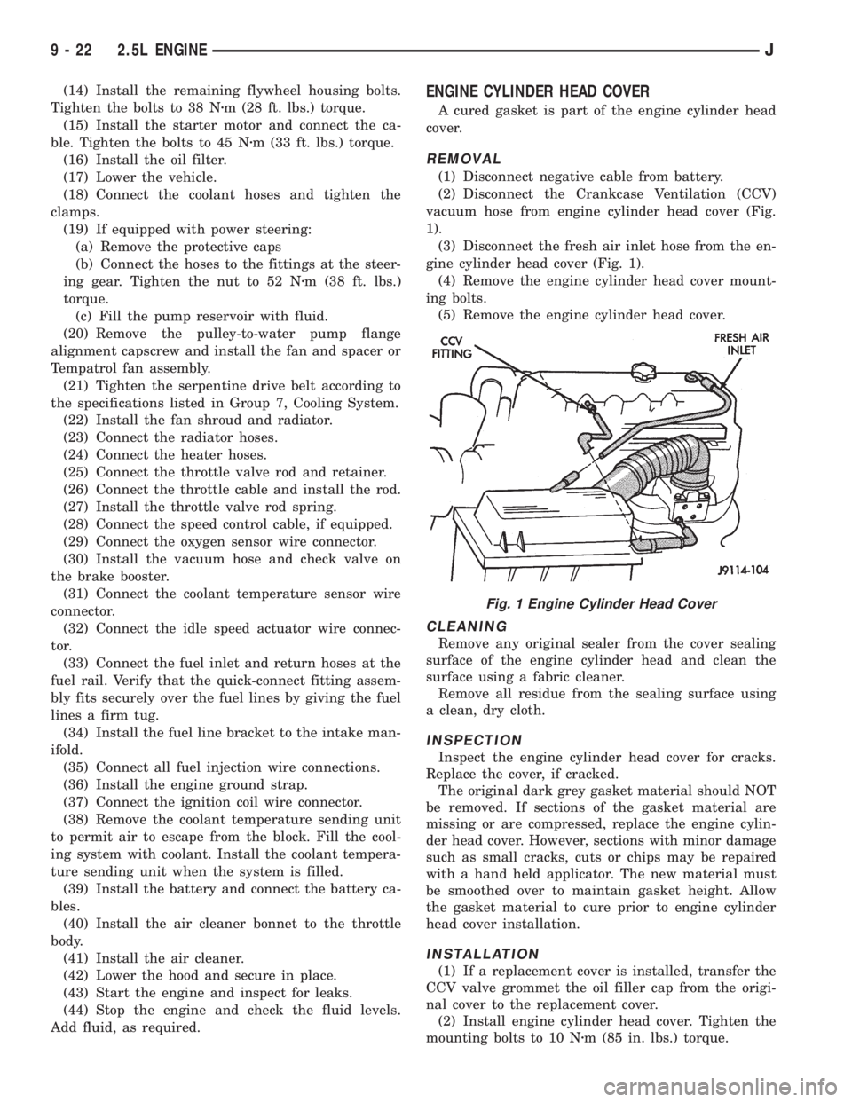
(2) Disconnect the Crankcase Ventilation (CCV)
vacuum hose from engine cylinder head cover (Fig.
1).
(3) Disconnect the fresh air inlet hose from the en-
gine cylinder head cover (Fig. 1).
(4) Remove the engine cylinder head cover mount-
ing bolts.
(5) Remove the engine cylinder head cover.
CLEANING
Remove any original sealer from the cover sealing
surface of the engine cylinder head and clean the
surface using a fabric cleaner.
Remove all residue from the sealing surface using
a clean, dry cloth.
INSPECTION
Inspect the engine cylinder head cover for cracks.
Replace the cover, if cracked.
The original dark grey gasket material should NOT
be removed. If sections of the gasket material are
missing or are compressed, replace the engine cylin-
der head cover. However, sections with minor damage
such as small cracks, cuts or chips may be repaired
with a hand held applicator. The new material must
be smoothed over to maintain gasket height. Allow
the gasket material to cure prior to engine cylinder
head cover installation.
INSTALLATION
(1) If a replacement cover is installed, transfer the
CCV valve grommet the oil filler cap from the origi-
nal cover to the replacement cover.
(2) Install engine cylinder head cover. Tighten the
mounting bolts to 10 Nzm (85 in. lbs.) torque.
Fig. 1 Engine Cylinder Head Cover
9 - 22 2.5L ENGINEJ
Page 1343 of 2158
(16) Remove the pulley-to-water pump flange
alignment capscrew and install the fan and spacer or
Tempatrol fan assembly.
(17) Tighten the serpentine drive belt according to
the specifications listed in Group 7, Cooling System.
(18) Install the fan shroud and radiator (refer to
Group 7, Cooling System for the proper procedure).
(19) Connect the radiator hoses.
(20) Connect the throttle valve rod and retainer.
(21) Connect the throttle cable and install the rod.
(22) Install the throttle valve rod spring.
(23) Connect the speed control cable, if equipped.
(24) Connect the oxygen sensor wire connector.
(25) Install the vacuum hose and check valve on
the brake booster.
(26) Connect the coolant temperature sensor wire
connector.
(27) Connect the idle speed actuator wire connec-
tor.
(28) Connect the fuel inlet and return hoses at the
fuel rail. Verify that the quick-connect fitting assem-
bly fits securely over the fuel lines by giving the fuel
lines a firm tug.
(29) Install the fuel line bracket to the intake man-
ifold.
(30) Connect all fuel injection wire connections.
(31) Install the engine ground strap.
(32) Connect the ignition coil wire connector.
(33) Remove the coolant temperature sending unit
to permit air to escape from the block. Fill the cool-
ing system with coolant. Install the coolant tempera-
ture sending unit when the system is filled.
(34) If equipped with power steering:
(a) Remove the protective caps
(b) Connect the hoses to the fittings at the steer-
ing gear. Tighten the nut to 52 Nzm (38 ft. lbs.)
torque.
(c) Fill the pump reservoir with fluid.
(35) Install the battery and connect the battery ca-
bles.
(36) Install the air cleaner bonnet to the throttle
body.
(37) Install the air cleaner.
(38) Lower the hood and secure in place.
(39) Start the engine and inspect for leaks.
(40) Stop the engine and check the fluid levels.
Add fluid, as required.
ENGINE CYLINDER HEAD COVER
A cured gasket is part of the engine cylinder head
cover.
REMOVAL
(1) Disconnect negative cable from battery.
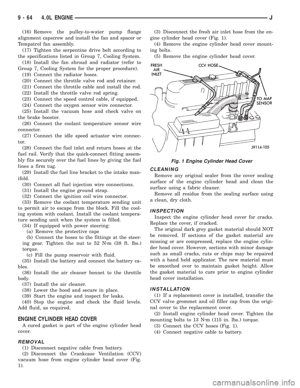
(2) Disconnect the Crankcase Ventilation (CCV)
vacuum hose from engine cylinder head cover (Fig.
1).(3) Disconnect the fresh air inlet hose from the en-
gine cylinder head cover (Fig. 1).
(4) Remove the engine cylinder head cover mount-
ing bolts.
(5) Remove the engine cylinder head cover.
CLEANING
Remove any original sealer from the cover sealing
surface of the engine cylinder head and clean the
surface using a fabric cleaner.
Remove all residue from the sealing surface using
a clean, dry cloth.
INSPECTION
Inspect the engine cylinder head cover for cracks.
Replace the cover, if cracked.
The original dark grey gasket material should NOT
be removed. If sections of the gasket material are
missing or are compressed, replace the engine cylin-
der head cover. However, sections with minor damage
such as small cracks, cuts or chips may be repaired
with a hand held applicator. The new material must
be smoothed over to maintain gasket height. Allow
the gasket material to cure prior to engine cylinder
head cover installation.
INSTALLATION
(1) If a replacement cover is installed, transfer the
CCV valve grommet and oil filler cap from the origi-
nal cover to the replacement cover.
(2) Install engine cylinder head cover. Tighten the
mounting bolts to 13 Nzm (115 in. lbs.) torque.
(3) Connect the CCV hoses (Fig. 1).
(4) Connect negative cable to battery.
Fig. 1 Engine Cylinder Head Cover
9 - 64 4.0L ENGINEJ