JEEP YJ 1995 Service And Repair Manual
Manufacturer: JEEP, Model Year: 1995, Model line: YJ, Model: JEEP YJ 1995Pages: 2158, PDF Size: 81.9 MB
Page 291 of 2158
the specific gravity for temperature variation. Test
the specific gravity of the electrolyte in each battery
cell.
Example: A battery is tested at -12.2ÉC (10ÉF) and
has a specific gravity of 1.240. Determine the actual
specific gravity as follows:
(1) Determine the number of degrees above or be-
low 26.7ÉC (80ÉF):
26.6ÉC - -12.2ÉC = 38.8ÉC (80ÉF - 10ÉF = 70ÉF)
(2) Divide the result from step 1 by 5.5 (10):
38.8ÉC/5.5 = 7 (70ÉF/10 = 7)
(3) Multiply the result from step 2 by the temper-
ature correction factor (0.004):
7 x 0.004 = 0.028
(4) The temperature at testing was below 26.7ÉC
(80ÉF); therefore, the temperature correction is sub-
tracted:
1.240 - 0.028 = 1.212
The corrected specific gravity of the battery in this
example is 1.212.
If the specific gravity of all cells is above 1.235, but
variation between cells is more than 50 points
(0.050), the battery should be replaced.
If the specific gravity of one or more cells is less
than 1.235, charge the battery at a rate of approxi-
mately 5 amperes. Continue charging until 3 consec-
utive specific gravity tests, taken at 1-hour intervals,
are constant. If the cell specific gravity variation is
more than 50 points (0.050) at the end of the charge
period, replace the battery.
When the specific gravity of all cells is above 1.235,
and cell variation is less than 50 points (0.050), the
battery may be load tested.
OPEN CIRCUIT VOLTAGE TEST
A battery open circuit voltage (no load) test will
show state-of-charge of a battery. This test can be
used in place of the hydrometer test if a hydrometer
is not available, or for maintenance-free batteries
with non-removable cell caps.
Before proceeding with this test or load test,
completely charge battery as described in Bat-
tery Charging in this group.
Test battery open circuit voltage as follows:
(1) Before measuring open circuit voltage the sur-
face charge must be removed from the battery. Turn
headlamps on for 15 seconds, then allow up to 5 min-
utes for voltage to stabilize.
(2) Remove both battery cables, negative first.
(3) Using a voltmeter connected to the battery
posts (refer to instructions provided with voltmeter)
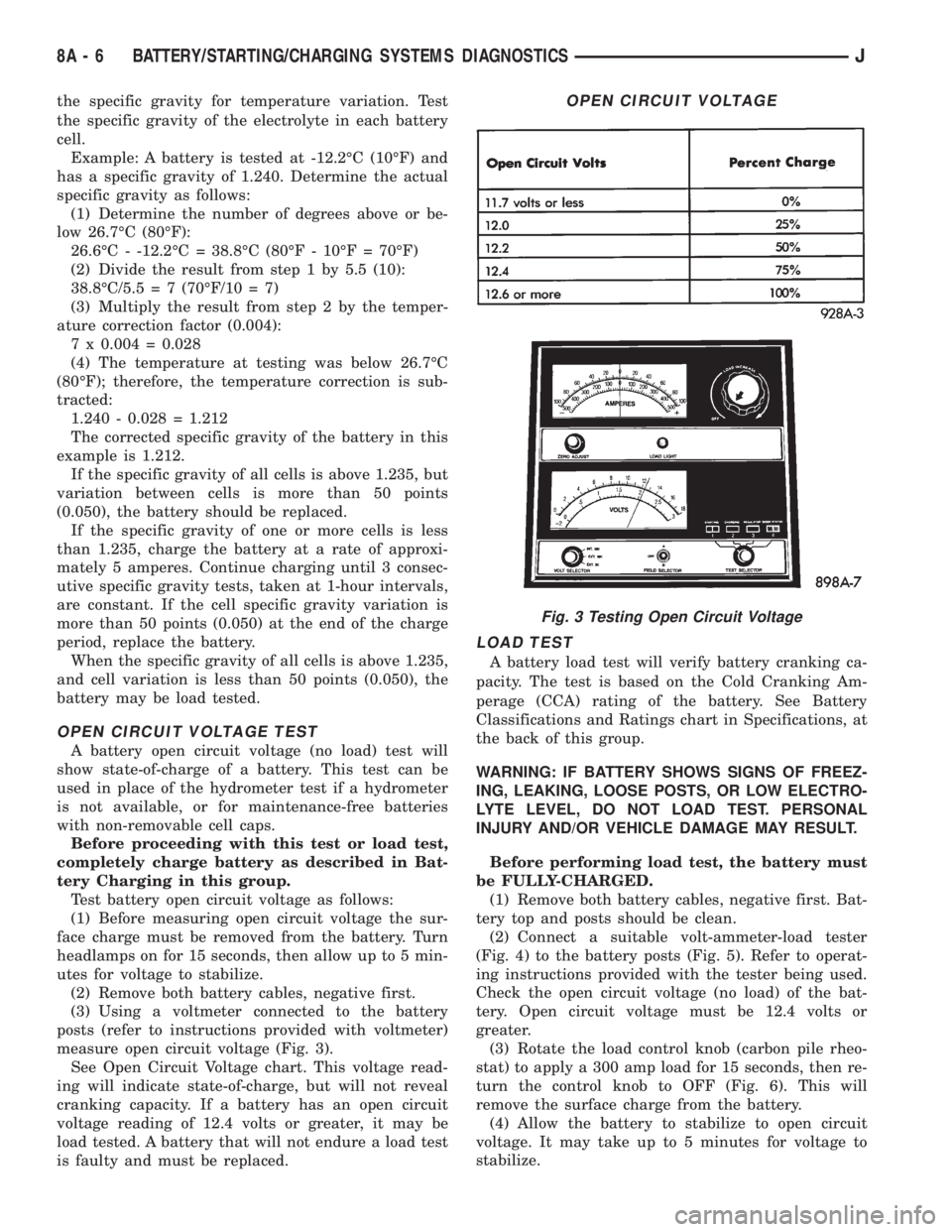
measure open circuit voltage (Fig. 3).
See Open Circuit Voltage chart. This voltage read-
ing will indicate state-of-charge, but will not reveal
cranking capacity. If a battery has an open circuit
voltage reading of 12.4 volts or greater, it may be
load tested. A battery that will not endure a load test
is faulty and must be replaced.
LOAD TEST
A battery load test will verify battery cranking ca-
pacity. The test is based on the Cold Cranking Am-
perage (CCA) rating of the battery. See Battery
Classifications and Ratings chart in Specifications, at
the back of this group.
WARNING: IF BATTERY SHOWS SIGNS OF FREEZ-
ING, LEAKING, LOOSE POSTS, OR LOW ELECTRO-
LYTE LEVEL, DO NOT LOAD TEST. PERSONAL
INJURY AND/OR VEHICLE DAMAGE MAY RESULT.
Before performing load test, the battery must
be FULLY-CHARGED.
(1) Remove both battery cables, negative first. Bat-
tery top and posts should be clean.
(2) Connect a suitable volt-ammeter-load tester
(Fig. 4) to the battery posts (Fig. 5). Refer to operat-
ing instructions provided with the tester being used.
Check the open circuit voltage (no load) of the bat-
tery. Open circuit voltage must be 12.4 volts or
greater.
(3) Rotate the load control knob (carbon pile rheo-
stat) to apply a 300 amp load for 15 seconds, then re-
turn the control knob to OFF (Fig. 6). This will
remove the surface charge from the battery.
(4) Allow the battery to stabilize to open circuit
voltage. It may take up to 5 minutes for voltage to
stabilize.
OPEN CIRCUIT VOLTAGE
Fig. 3 Testing Open Circuit Voltage
8A - 6 BATTERY/STARTING/CHARGING SYSTEMS DIAGNOSTICSJ
Page 292 of 2158
(5) Rotate the load control knob to maintain a load
equal to 50% of CCA rating (Fig. 7). After 15 seconds,
record the loaded voltage reading, then return the
load control knob to OFF.
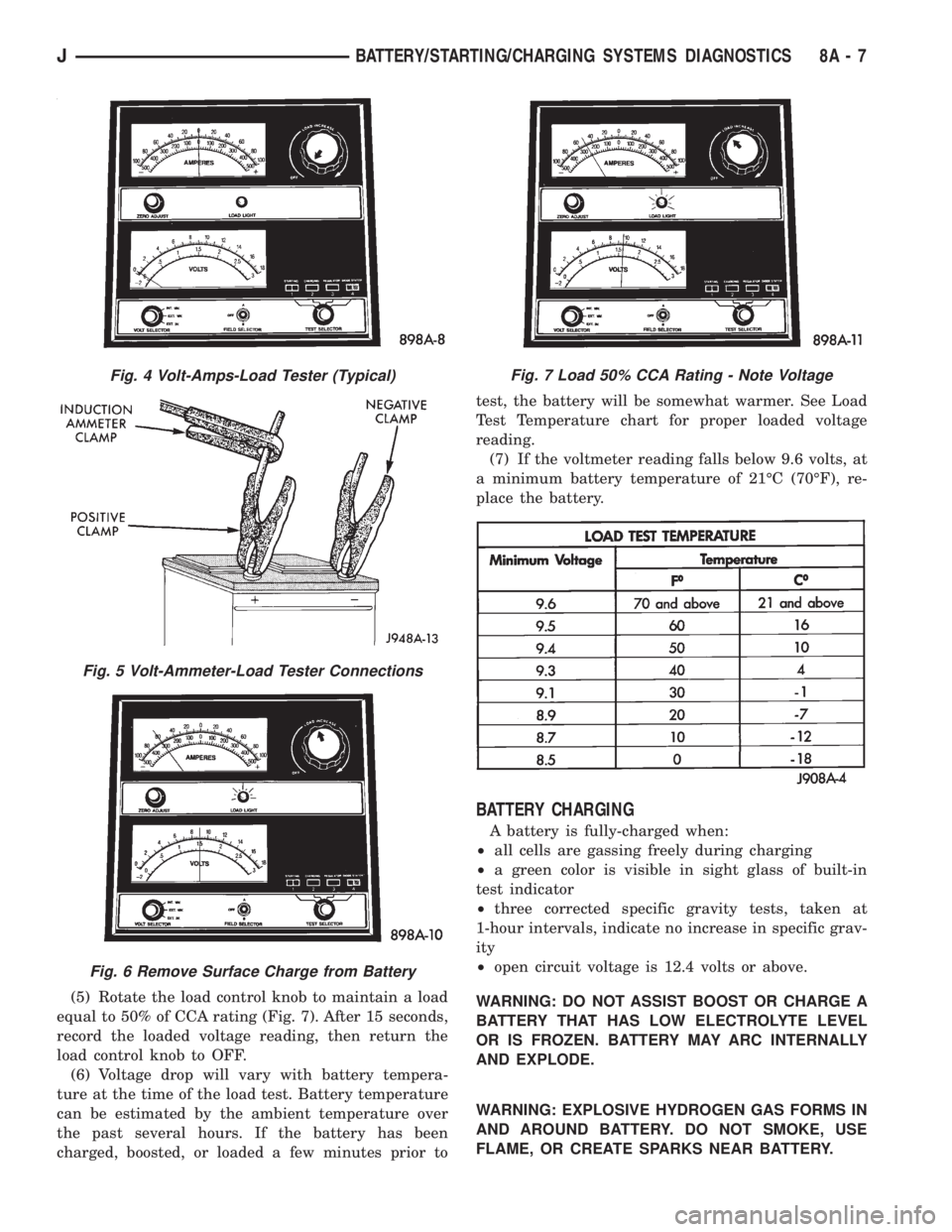
(6) Voltage drop will vary with battery tempera-
ture at the time of the load test. Battery temperature
can be estimated by the ambient temperature over
the past several hours. If the battery has been
charged, boosted, or loaded a few minutes prior totest, the battery will be somewhat warmer. See Load
Test Temperature chart for proper loaded voltage
reading.
(7) If the voltmeter reading falls below 9.6 volts, at
a minimum battery temperature of 21ÉC (70ÉF), re-
place the battery.
BATTERY CHARGING
A battery is fully-charged when:
┬▓all cells are gassing freely during charging
┬▓a green color is visible in sight glass of built-in
test indicator
┬▓three corrected specific gravity tests, taken at
1-hour intervals, indicate no increase in specific grav-
ity
┬▓open circuit voltage is 12.4 volts or above.
WARNING: DO NOT ASSIST BOOST OR CHARGE A
BATTERY THAT HAS LOW ELECTROLYTE LEVEL
OR IS FROZEN. BATTERY MAY ARC INTERNALLY
AND EXPLODE.
WARNING: EXPLOSIVE HYDROGEN GAS FORMS IN
AND AROUND BATTERY. DO NOT SMOKE, USE
FLAME, OR CREATE SPARKS NEAR BATTERY.
Fig. 4 Volt-Amps-Load Tester (Typical)
Fig. 5 Volt-Ammeter-Load Tester Connections
Fig. 6 Remove Surface Charge from Battery
Fig. 7 Load 50% CCA Rating - Note Voltage
JBATTERY/STARTING/CHARGING SYSTEMS DIAGNOSTICS 8A - 7
Page 293 of 2158
WARNING: POISONOUS AND CAUSTIC. BATTERY
CONTAINS SULFURIC ACID. AVOID CONTACT WITH
SKIN, EYES, OR CLOTHING. IN EVENT OF CON-
TACT, FLUSH WITH WATER AND CALL PHYSICIAN
IMMEDIATELY. KEEP OUT OF REACH OF CHIL-
DREN.
CAUTION: Always disconnect the battery negative
cable before charging battery to avoid damage to
electrical system components. Do not exceed 16.0
volts while charging battery.
Battery electrolyte will bubble inside battery case
during normal battery charging. If the electrolyte
boils, or is discharged from the vent holes while
charging, immediately reduce charging rate or turn
OFF charger and evaluate battery condition.
Battery should not be hot to the touch. If the
battery feels hot to the touch, turn OFF
charger and let battery cool before continuing
charging operation.
Some battery chargers are equipped with polarity
sensing circuitry. This circuitry protects the charger
and/or battery from being damaged if improperly con-
nected.
If the battery state-of-charge is too low for the po-
larity sensing circuitry to detect, the charger will not
operate. This makes it appear that the battery will
not accept charging current. Refer to instructions
provided with the battery charger being used to by-
pass the polarity sensing circuitry.
After the battery has been charged to 12.4 volts or
greater, perform a load test to determine cranking
capacity. If the battery will endure a load test, return
the battery to use. If the battery will not endure a
load test, it must be replaced.
Clean and inspect battery holddowns, tray, termi-
nals, posts, and top before completing service. Refer
to Group 8B - Battery/Starter/Generator Service for
more information.
CHARGING TIME REQUIRED
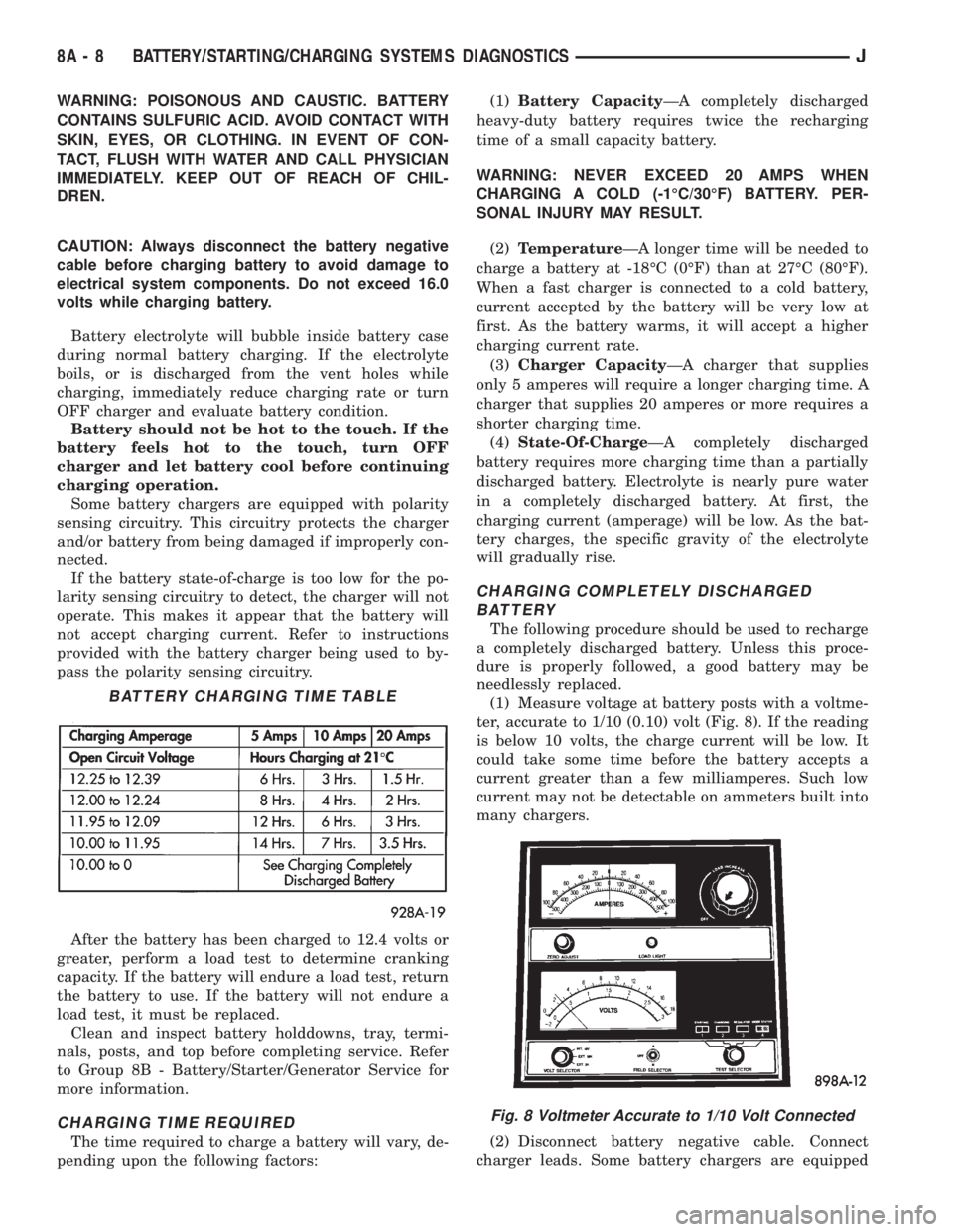
The time required to charge a battery will vary, de-
pending upon the following factors:(1)Battery CapacityÐA completely discharged
heavy-duty battery requires twice the recharging
time of a small capacity battery.
WARNING: NEVER EXCEED 20 AMPS WHEN
CHARGING A COLD (-1ÉC/30ÉF) BATTERY. PER-
SONAL INJURY MAY RESULT.
(2)TemperatureÐA longer time will be needed to
charge a battery at -18ÉC (0ÉF) than at 27ÉC (80ÉF).
When a fast charger is connected to a cold battery,
current accepted by the battery will be very low at
first. As the battery warms, it will accept a higher
charging current rate.
(3)Charger CapacityÐA charger that supplies
only 5 amperes will require a longer charging time. A
charger that supplies 20 amperes or more requires a
shorter charging time.
(4)State-Of-ChargeÐA completely discharged
battery requires more charging time than a partially
discharged battery. Electrolyte is nearly pure water
in a completely discharged battery. At first, the
charging current (amperage) will be low. As the bat-
tery charges, the specific gravity of the electrolyte
will gradually rise.
CHARGING COMPLETELY DISCHARGED
BATTERY
The following procedure should be used to recharge
a completely discharged battery. Unless this proce-
dure is properly followed, a good battery may be
needlessly replaced.
(1) Measure voltage at battery posts with a voltme-
ter, accurate to 1/10 (0.10) volt (Fig. 8). If the reading
is below 10 volts, the charge current will be low. It
could take some time before the battery accepts a
current greater than a few milliamperes. Such low
current may not be detectable on ammeters built into
many chargers.
(2) Disconnect battery negative cable. Connect
charger leads. Some battery chargers are equipped
BATTERY CHARGING TIME TABLE
Fig. 8 Voltmeter Accurate to 1/10 Volt Connected
8A - 8 BATTERY/STARTING/CHARGING SYSTEMS DIAGNOSTICSJ
Page 294 of 2158
with polarity sensing circuitry. This circuitry protects
the charger and/or battery from being damaged if im-
properly connected. If the battery state-of-charge is
too low for the polarity sensing circuitry to detect,
the charger will not operate. This makes it appear
that the battery will not accept charging current. Re-
fer to the instructions provided with the battery
charger to bypass the polarity sensing circuitry.
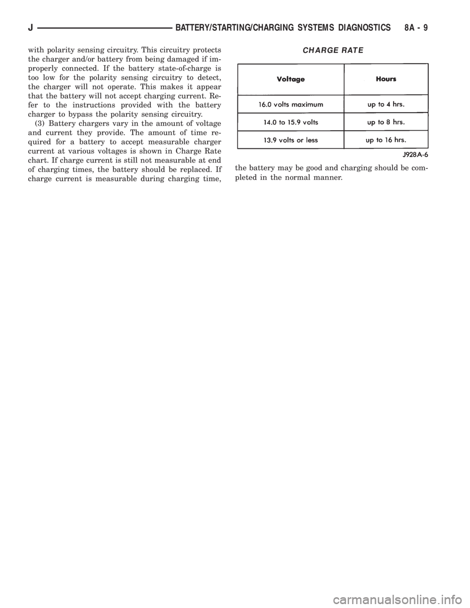
(3) Battery chargers vary in the amount of voltage
and current they provide. The amount of time re-
quired for a battery to accept measurable charger
current at various voltages is shown in Charge Rate
chart. If charge current is still not measurable at end
of charging times, the battery should be replaced. If
charge current is measurable during charging time,the battery may be good and charging should be com-
pleted in the normal manner.CHARGE RATE
JBATTERY/STARTING/CHARGING SYSTEMS DIAGNOSTICS 8A - 9
Page 295 of 2158
IGNITION-OFF DRAW
GENERAL INFORMATION
Ignition-Off Draw (IOD) refers to power being
drained from the battery with the ignition switch
turned OFF. A normal vehicle electrical system will
draw from 5 to 20 milliamps (0.005 - 0.020 amps).
This is with the ignition switch in the OFF position,
and all non-ignition controlled circuits in proper
working order. The 20 milliamps are needed to sup-
ply PCM memory, digital clock memory, and electron-
ically-tuned radio memory.
A vehicle that has not been operated for approxi-
mately 20 days, may discharge the battery to an in-
adequate level. When a vehicle will not be used for
20 days or more (stored), remove the IOD fuse in the
Power Distribution Center (PDC). This will reduce
battery discharging.
Excessive battery drain can be caused by:
┬▓electrical items left on
┬▓faulty or improperly adjusted switches
┬▓internally shorted generator
┬▓intermittent shorts in the wiring.
If the IOD is over 20 milliamps, the problem must
be found and corrected before replacing a battery. In
most cases, the battery can be charged and returned
to service.
DIAGNOSIS
Testing for high-amperage IOD must be per-
formed first to prevent damage to most milli-
amp meters.
(1) Verify that all electrical accessories are off.
Turn off all lamps, remove ignition key, and close all
doors. If the vehicle is equipped with illuminated en-
try or electronically-tuned radio, allow the systems to
automatically shut off (time out). This may take up
to 3 minutes.
(2) Determine that the underhood lamp is operat-
ing properly, then disconnect or remove bulb.
(3) Disconnect negative cable from battery.
(4) Connect a typical 12-volt test lamp (low-watt-
age bulb) between the negative cable clamp and the
battery negative terminal. Make sure that the doors
remain closed so that illuminated entry is not acti-
vated.The test lamp may light brightly for up to 3 min-
utes, or may not light at all, depending upon the ve-
hicle's electrical equipment. The term brightly, as
used throughout the following tests, implies the
brightness of the test lamp will be the same as if it
were connected across the battery.
The test lamp must be securely clamped to the neg-
ative cable clamp and battery negative terminal. If
the test lamp becomes disconnected during any part
of the IOD test, the electronic timer function will be
activated and all tests must be repeated.
(5) After 3 minutes the test lamp should turn off
or be dimly lit, depending upon the vehicle's electri-
cal equipment. If the test lamp remains brightly lit,
do not disconnect it. Remove each fuse or circuit
breaker (refer to Group 8W - Wiring Diagrams) until
test lamp is either off or dimly lit. This will isolate
each circuit and identify the source of the high-am-
perage draw.
If the test lamp is still brightly lit after disconnect-
ing each fuse and circuit breaker, disconnect the wir-
ing harness from the generator. If test lamp now
turns off or is dimly lit, see Charging System in this
group to diagnose faulty generator. Do not disconnect
the test lamp.
After high-amperage IOD has been corrected, low-
amperage IOD may be checked. It is now safe to in-
stall a milliamp meter to check for low- amperage
IOD.
(6) With test lamp still connected securely, clamp a
milliamp meter between battery negative terminal
and negative cable clamp.
Do not open any doors or turn on any electri-
cal accessories with the test lamp disconnected
or the milliamp meter may be damaged.
(7) Disconnect test lamp. Observe milliamp meter.
The current draw should not exceed 0.020 amp. If
draw exceeds 20 milliamps, isolate each circuit by re-
moving circuit breakers and fuses. The milliamp
meter reading will drop when the source of the draw
is disconnected. Repair this circuit as necessary,
whether a wiring short, incorrect switch adjustment
or a component failure is found.
8A - 10 BATTERY/STARTING/CHARGING SYSTEMS DIAGNOSTICSJ
Page 296 of 2158
STARTING SYSTEM
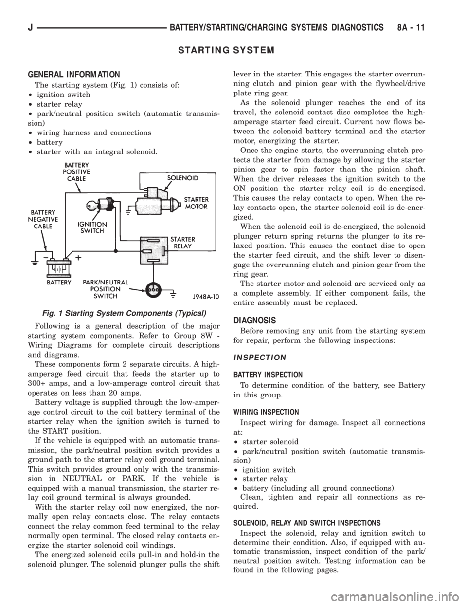
GENERAL INFORMATION
The starting system (Fig. 1) consists of:
┬▓ignition switch
┬▓starter relay
┬▓park/neutral position switch (automatic transmis-
sion)
┬▓wiring harness and connections
┬▓battery
┬▓starter with an integral solenoid.
Following is a general description of the major
starting system components. Refer to Group 8W -
Wiring Diagrams for complete circuit descriptions
and diagrams.
These components form 2 separate circuits. A high-
amperage feed circuit that feeds the starter up to
300+ amps, and a low-amperage control circuit that
operates on less than 20 amps.
Battery voltage is supplied through the low-amper-
age control circuit to the coil battery terminal of the
starter relay when the ignition switch is turned to
the START position.
If the vehicle is equipped with an automatic trans-
mission, the park/neutral position switch provides a
ground path to the starter relay coil ground terminal.
This switch provides ground only with the transmis-
sion in NEUTRAL or PARK. If the vehicle is
equipped with a manual transmission, the starter re-
lay coil ground terminal is always grounded.
With the starter relay coil now energized, the nor-
mally open relay contacts close. The relay contacts
connect the relay common feed terminal to the relay
normally open terminal. The closed relay contacts en-
ergize the starter solenoid coil windings.
The energized solenoid coils pull-in and hold-in the
solenoid plunger. The solenoid plunger pulls the shiftlever in the starter. This engages the starter overrun-
ning clutch and pinion gear with the flywheel/drive
plate ring gear.
As the solenoid plunger reaches the end of its
travel, the solenoid contact disc completes the high-
amperage starter feed circuit. Current now flows be-
tween the solenoid battery terminal and the starter
motor, energizing the starter.
Once the engine starts, the overrunning clutch pro-
tects the starter from damage by allowing the starter
pinion gear to spin faster than the pinion shaft.
When the driver releases the ignition switch to the
ON position the starter relay coil is de-energized.
This causes the relay contacts to open. When the re-
lay contacts open, the starter solenoid coil is de-ener-
gized.
When the solenoid coil is de-energized, the solenoid
plunger return spring returns the plunger to its re-
laxed position. This causes the contact disc to open
the starter feed circuit, and the shift lever to disen-
gage the overrunning clutch and pinion gear from the
ring gear.
The starter motor and solenoid are serviced only as
a complete assembly. If either component fails, the
entire assembly must be replaced.
DIAGNOSIS
Before removing any unit from the starting system
for repair, perform the following inspections:
INSPECTION
BATTERY INSPECTION
To determine condition of the battery, see Battery
in this group.
WIRING INSPECTION
Inspect wiring for damage. Inspect all connections
at:
┬▓starter solenoid
┬▓park/neutral position switch (automatic transmis-
sion)
┬▓ignition switch
┬▓starter relay
┬▓battery (including all ground connections).
Clean, tighten and repair all connections as re-
quired.
SOLENOID, RELAY AND SWITCH INSPECTIONS
Inspect the solenoid, relay and ignition switch to
determine their condition. Also, if equipped with au-
tomatic transmission, inspect condition of the park/
neutral position switch. Testing information can be
found in the following pages.
Fig. 1 Starting System Components (Typical)
JBATTERY/STARTING/CHARGING SYSTEMS DIAGNOSTICS 8A - 11
Page 297 of 2158
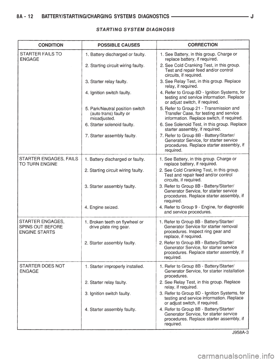
STARTING SYSTEM DIAGNOSIS
8A - 12 BATTERY/STARTING/CHARGING SYSTEMS DIAGNOSTICSJ
Page 298 of 2158
COLD CRANKING TEST
(1) Battery must be fully-charged and load tested
before proceeding. See Battery, in this group.
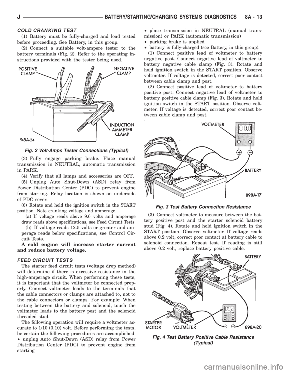
(2) Connect a suitable volt-ampere tester to the
battery terminals (Fig. 2). Refer to the operating in-
structions provided with the tester being used.
(3) Fully engage parking brake. Place manual
transmission in NEUTRAL, automatic transmission
in PARK.
(4) Verify that all lamps and accessories are OFF.
(5) Unplug Auto Shut-Down (ASD) relay from
Power Distribution Center (PDC) to prevent engine
from starting. Relay location is shown on underside
of PDC cover.
(6) Rotate and hold the ignition switch in the START
position. Note cranking voltage and amperage.
(a) If voltage reads above 9.6 volts and amperage
draw reads above specifications, see Feed Circuit Tests.
(b) If voltage reads 12.5 volts or greater and am-
perage reads below specifications, see Control Cir-
cuit Tests.
A cold engine will increase starter current
and reduce battery voltage.
FEED CIRCUIT TESTS
The starter feed circuit tests (voltage drop method)
will determine if there is excessive resistance in the
high-amperage circuit. When performing these tests,
it is important that the voltmeter be connected prop-
erly. Connect voltmeter leads to the terminals that
the cable connectors or clamps are attached to, not to
the cable connectors or clamps. For example: When
testing between the battery and solenoid, touch the
voltmeter leads to the battery post and the solenoid
threaded stud.
The following operation will require a voltmeter ac-
curate to 1/10 (0.10) volt. Before performing the tests,
be certain the following procedures are accomplished:
┬▓unplug Auto Shut-Down (ASD) relay from Power
Distribution Center (PDC) to prevent engine from
starting┬▓place transmission in NEUTRAL (manual trans-
mission) or PARK (automatic transmission)
┬▓parking brake is applied
┬▓
battery is fully-charged (see Battery, in this group).
(1) Connect positive lead of voltmeter to battery
negative post. Connect negative lead of voltmeter to
battery negative cable clamp (Fig. 3). Rotate and
hold ignition switch in the START position. Observe
voltmeter. If voltage is detected, correct poor contact
between cable clamp and post.
(2) Connect positive lead of voltmeter to battery
positive post. Connect negative lead of voltmeter to
battery positive cable clamp (Fig. 3). Rotate and hold
ignition switch in the START position. Observe volt-
meter. If voltage is detected, correct poor contact be-
tween cable clamp and post.
(3) Connect voltmeter to measure between the bat-
tery positive post and the starter solenoid battery
stud (Fig. 4). Rotate and hold ignition switch in the
START position. Observe voltmeter. If voltage reads
above 0.2 volt, correct poor contact at battery cable to
solenoid connection. Repeat test. If reading is still
above 0.2 volt, replace battery positive cable.
Fig. 2 Volt-Amps Tester Connections (Typical)
Fig. 3 Test Battery Connection Resistance
Fig. 4 Test Battery Positive Cable Resistance
(Typical)
JBATTERY/STARTING/CHARGING SYSTEMS DIAGNOSTICS 8A - 13
Page 299 of 2158
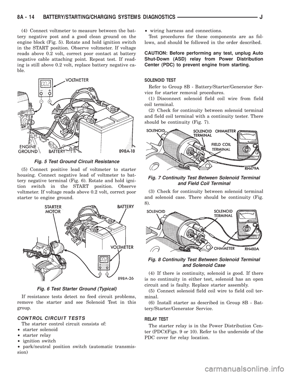
(4) Connect voltmeter to measure between the bat-
tery negative post and a good clean ground on the
engine block (Fig. 5). Rotate and hold ignition switch
in the START position. Observe voltmeter. If voltage
reads above 0.2 volt, correct poor contact at battery
negative cable attaching point. Repeat test. If read-
ing is still above 0.2 volt, replace battery negative ca-
ble.
(5) Connect positive lead of voltmeter to starter
housing. Connect negative lead of voltmeter to bat-
tery negative terminal (Fig. 6). Rotate and hold igni-
tion switch in the START position. Observe
voltmeter. If voltage reads above 0.2 volt, correct poor
starter to engine ground.
If resistance tests detect no feed circuit problems,
remove the starter and see Solenoid Test in this
group.
CONTROL CIRCUIT TESTS
The starter control circuit consists of:
┬▓starter solenoid
┬▓starter relay
┬▓ignition switch
┬▓park/neutral position switch (automatic transmis-
sion)┬▓wiring harness and connections.
Test procedures for these components are as fol-
lows, and should be followed in the order described.
CAUTION: Before performing any test, unplug Auto
Shut-Down (ASD) relay from Power Distribution
Center (PDC) to prevent engine from starting.
SOLENOID TEST
Refer to Group 8B - Battery/Starter/Generator Ser-
vice for starter removal procedures.
(1) Disconnect solenoid field coil wire from field
coil terminal.
(2) Check for continuity between solenoid terminal
and field coil terminal with a continuity tester. There
should be continuity (Fig. 7).
(3) Check for continuity between solenoid terminal
and solenoid case. There should be continuity (Fig.
8).
(4) If there is continuity, solenoid is good. If there
is no continuity in either test, solenoid has an open
circuit and is faulty. Replace starter assembly.
(5) Connect solenoid field coil wire to field coil ter-
minal.
(6) Install starter as described in Group 8B - Bat-
tery/Starter/Generator Service.
RELAY TEST
The starter relay is in the Power Distribution Cen-
ter (PDC)(Figs. 9 or 10). Refer to the underside of the
PDC cover for relay location.
Fig. 5 Test Ground Circuit Resistance
Fig. 6 Test Starter Ground (Typical)
Fig. 7 Continuity Test Between Solenoid Terminal
and Field Coil Terminal
Fig. 8 Continuity Test Between Solenoid Terminal
and Solenoid Case
8A - 14 BATTERY/STARTING/CHARGING SYSTEMS DIAGNOSTICSJ
Page 300 of 2158
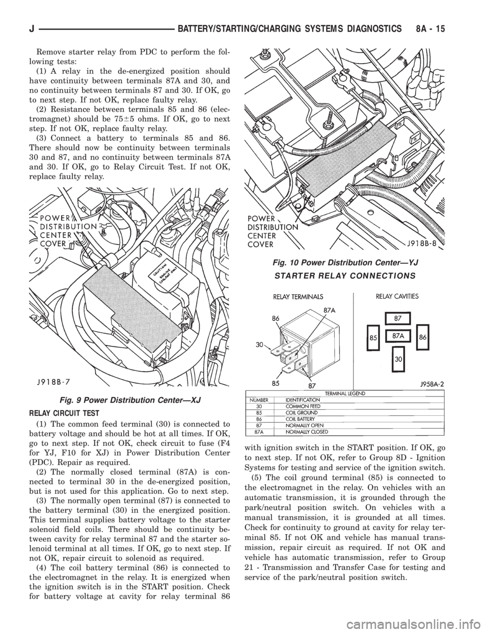
Remove starter relay from PDC to perform the fol-
lowing tests:
(1) A relay in the de-energized position should
have continuity between terminals 87A and 30, and
no continuity between terminals 87 and 30. If OK, go
to next step. If not OK, replace faulty relay.
(2) Resistance between terminals 85 and 86 (elec-
tromagnet) should be 7565 ohms. If OK, go to next
step. If not OK, replace faulty relay.
(3) Connect a battery to terminals 85 and 86.
There should now be continuity between terminals
30 and 87, and no continuity between terminals 87A
and 30. If OK, go to Relay Circuit Test. If not OK,
replace faulty relay.
RELAY CIRCUIT TEST
(1) The common feed terminal (30) is connected to
battery voltage and should be hot at all times. If OK,
go to next step. If not OK, check circuit to fuse (F4
for YJ, F10 for XJ) in Power Distribution Center
(PDC). Repair as required.
(2) The normally closed terminal (87A) is con-
nected to terminal 30 in the de-energized position,
but is not used for this application. Go to next step.
(3) The normally open terminal (87) is connected to
the battery terminal (30) in the energized position.
This terminal supplies battery voltage to the starter
solenoid field coils. There should be continuity be-
tween cavity for relay terminal 87 and the starter so-
lenoid terminal at all times. If OK, go to next step. If
not OK, repair circuit to solenoid as required.
(4) The coil battery terminal (86) is connected to
the electromagnet in the relay. It is energized when
the ignition switch is in the START position. Check
for battery voltage at cavity for relay terminal 86with ignition switch in the START position. If OK, go
to next step. If not OK, refer to Group 8D - Ignition
Systems for testing and service of the ignition switch.
(5) The coil ground terminal (85) is connected to
the electromagnet in the relay. On vehicles with an
automatic transmission, it is grounded through the
park/neutral position switch. On vehicles with a
manual transmission, it is grounded at all times.
Check for continuity to ground at cavity for relay ter-
minal 85. If not OK and vehicle has manual trans-
mission, repair circuit as required. If not OK and
vehicle has automatic transmission, refer to Group
21 - Transmission and Transfer Case for testing and
service of the park/neutral position switch.
Fig. 9 Power Distribution CenterÐXJ
Fig. 10 Power Distribution CenterÐYJ
STARTER RELAY CONNECTIONS
JBATTERY/STARTING/CHARGING SYSTEMS DIAGNOSTICS 8A - 15