JEEP YJ 1995 Service And Repair Manual
Manufacturer: JEEP, Model Year: 1995, Model line: YJ, Model: JEEP YJ 1995Pages: 2158, PDF Size: 81.9 MB
Page 331 of 2158
(8) If voltage is not present at supply wire, check
for voltage at pin-7 of powertrain control module
(PCM) 60-way connector. Leave the PCM connector
connected for this test.
(9) If voltage is still not present, perform vehicle
test using the DRB scan tool.
(10) If voltage is present at pin-7, but not at the
supply wire:
(a) Check continuity between the supply wire.
This is checked between the distributor connector
and pin-7 at the PCM. If continuity is not present,
repair the harness as necessary.
(b) Check for continuity between the camshaft
position sensor output wire and pin-44 at the PCM.
If continuity is not present, repair the harness as
necessary.
(c) Check for continuity between the ground cir-
cuit wire at the distributor connector and ground.
If continuity is not present, repair the harness as
necessary.
(11) While observing the voltmeter, crank the en-
gine with ignition switch. The voltmeter needle
should fluctuate between 0 and 5 volts while the en-
gine is cranking. This verifies that the camshaft po-
sition sensor in the distributor is operating properly
and a sync pulse signal is being generated.
If sync pulse signal is not present, replacement of
the camshaft position sensor is necessary.
For removal or installation of ignition system com-
ponents, refer to the Component Removal/Installa-
tion section of this group.
For system operation and component identification,
refer to the Component Identification/System Opera-
tion section of this group.
CRANKSHAFT POSITION SENSOR TEST
To perform a complete test of this sensor and its
circuitry, refer to the DRB scan tool. Also refer to the
appropriate Powertrain Diagnostics Procedures man-
ual. To test the sensor only, refer to the following:
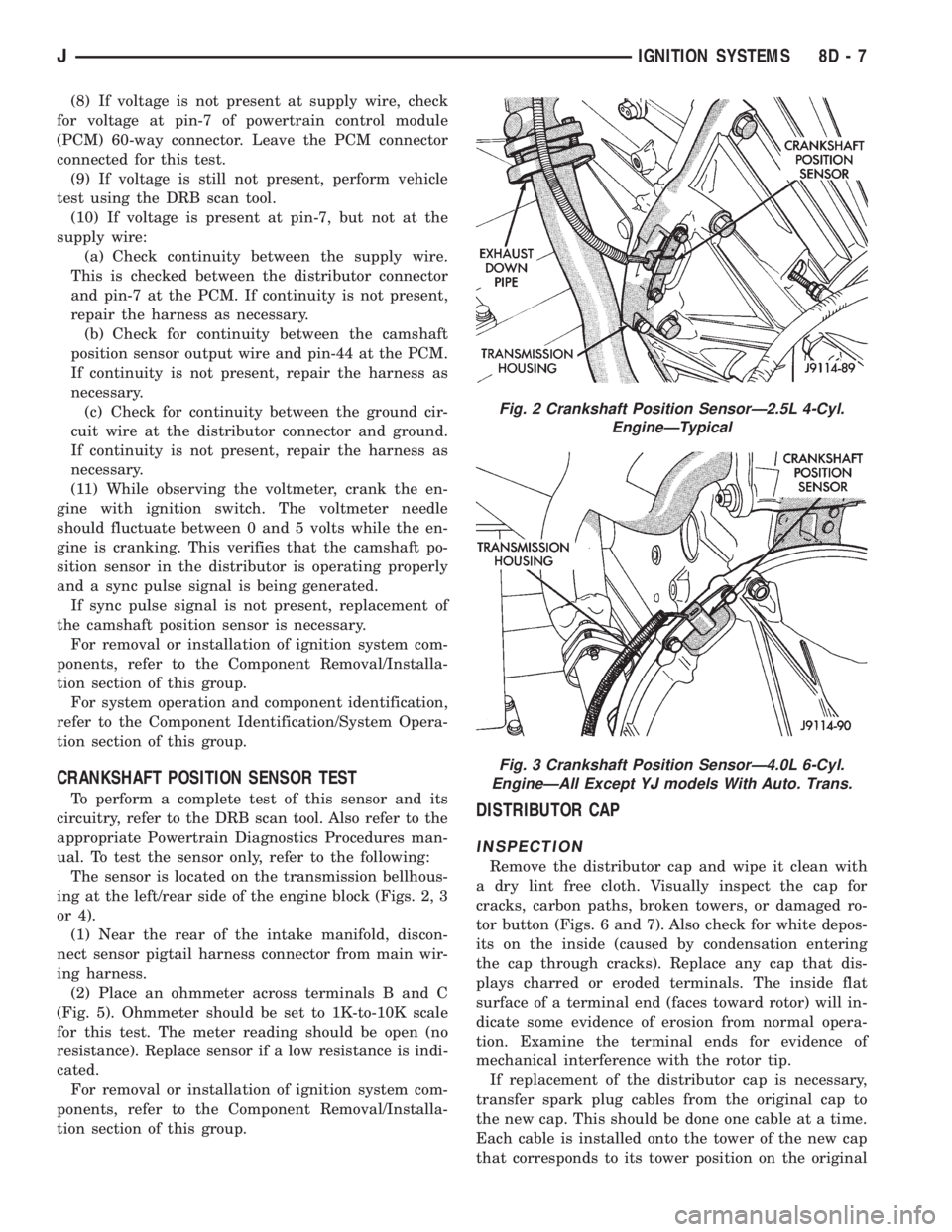
The sensor is located on the transmission bellhous-
ing at the left/rear side of the engine block (Figs. 2, 3
or 4).
(1) Near the rear of the intake manifold, discon-
nect sensor pigtail harness connector from main wir-
ing harness.
(2) Place an ohmmeter across terminals B and C
(Fig. 5). Ohmmeter should be set to 1K-to-10K scale
for this test. The meter reading should be open (no
resistance). Replace sensor if a low resistance is indi-
cated.
For removal or installation of ignition system com-
ponents, refer to the Component Removal/Installa-
tion section of this group.DISTRIBUTOR CAP
INSPECTION
Remove the distributor cap and wipe it clean with
a dry lint free cloth. Visually inspect the cap for
cracks, carbon paths, broken towers, or damaged ro-
tor button (Figs. 6 and 7). Also check for white depos-
its on the inside (caused by condensation entering
the cap through cracks). Replace any cap that dis-
plays charred or eroded terminals. The inside flat
surface of a terminal end (faces toward rotor) will in-
dicate some evidence of erosion from normal opera-
tion. Examine the terminal ends for evidence of
mechanical interference with the rotor tip.
If replacement of the distributor cap is necessary,
transfer spark plug cables from the original cap to
the new cap. This should be done one cable at a time.
Each cable is installed onto the tower of the new cap
that corresponds to its tower position on the original
Fig. 2 Crankshaft Position SensorÐ2.5L 4-Cyl.
EngineÐTypical
Fig. 3 Crankshaft Position SensorÐ4.0L 6-Cyl.
EngineÐAll Except YJ models With Auto. Trans.
JIGNITION SYSTEMS 8D - 7
Page 332 of 2158
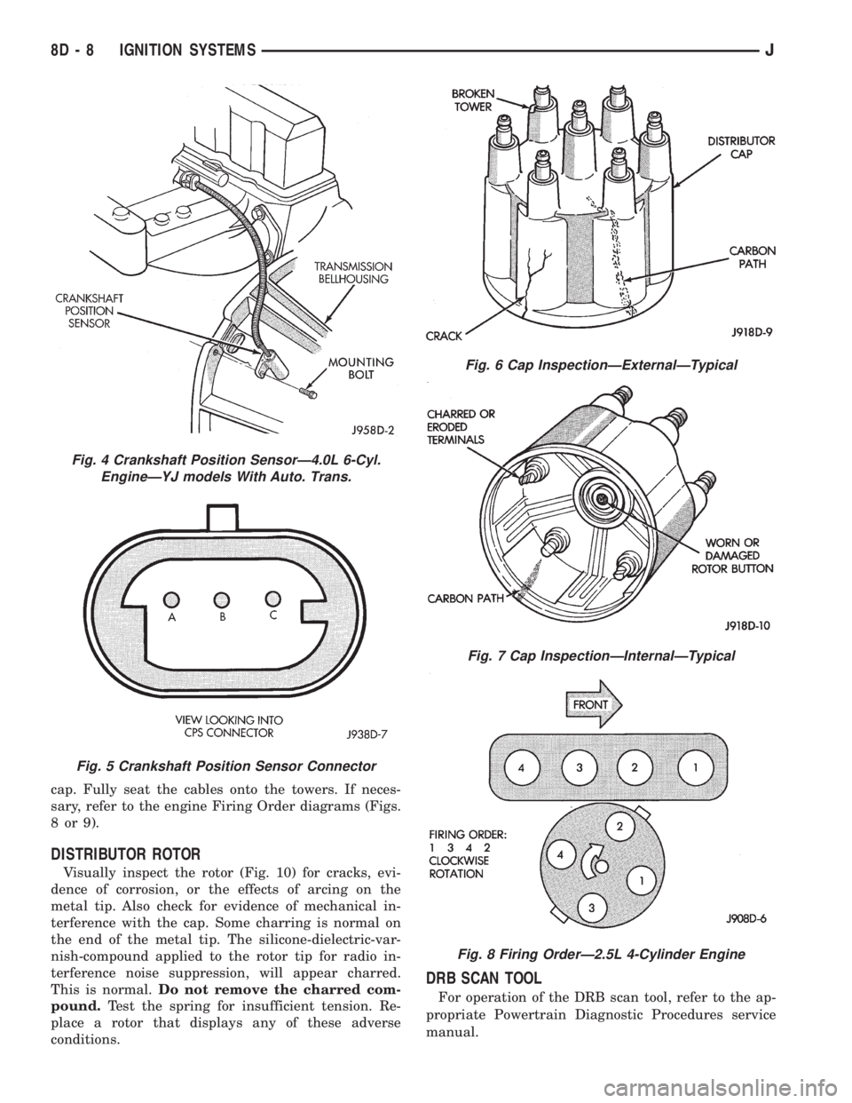
cap. Fully seat the cables onto the towers. If neces-
sary, refer to the engine Firing Order diagrams (Figs.
8or9).
DISTRIBUTOR ROTOR
Visually inspect the rotor (Fig. 10) for cracks, evi-
dence of corrosion, or the effects of arcing on the
metal tip. Also check for evidence of mechanical in-
terference with the cap. Some charring is normal on
the end of the metal tip. The silicone-dielectric-var-
nish-compound applied to the rotor tip for radio in-
terference noise suppression, will appear charred.
This is normal.Do not remove the charred com-
pound.Test the spring for insufficient tension. Re-
place a rotor that displays any of these adverse
conditions.
DRB SCAN TOOL
For operation of the DRB scan tool, refer to the ap-
propriate Powertrain Diagnostic Procedures service
manual.
Fig. 4 Crankshaft Position SensorÐ4.0L 6-Cyl.
EngineÐYJ models With Auto. Trans.
Fig. 5 Crankshaft Position Sensor Connector
Fig. 6 Cap InspectionÐExternalÐTypical
Fig. 7 Cap InspectionÐInternalÐTypical
Fig. 8 Firing OrderÐ2.5L 4-Cylinder Engine
8D - 8 IGNITION SYSTEMSJ
Page 333 of 2158
IGNITION COIL
To perform a complete test of the ignition coil and
its circuitry, refer to the DRB scan tool. Also refer tothe appropriate Powertrain Diagnostics Procedures
manual. To test the coil only, refer to the following:
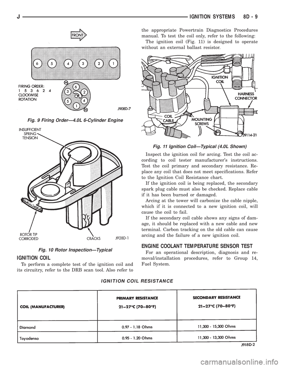
The ignition coil (Fig. 11) is designed to operate
without an external ballast resistor.
Inspect the ignition coil for arcing. Test the coil ac-
cording to coil tester manufacturer's instructions.
Test the coil primary and secondary resistance. Re-
place any coil that does not meet specifications. Refer
to the Ignition Coil Resistance chart.
If the ignition coil is being replaced, the secondary
spark plug cable must also be checked. Replace cable
if it has been burned or damaged.
Arcing at the tower will carbonize the cable nipple,
which if it is connected to a new ignition coil, will
cause the coil to fail.
If the secondary coil cable shows any signs of dam-
age, it should be replaced with a new cable and new
terminal. Carbon tracking on the old cable can cause
arcing and the failure of a new ignition coil.
ENGINE COOLANT TEMPERATURE SENSOR TEST
For an operational description, diagnosis and re-
moval/installation procedures, refer to Group 14,
Fuel System.
IGNITION COIL RESISTANCE
Fig. 9 Firing OrderÐ4.0L 6-Cylinder Engine
Fig. 10 Rotor InspectionÐTypical
Fig. 11 Ignition CoilÐTypical (4.0L Shown)
JIGNITION SYSTEMS 8D - 9
Page 334 of 2158
IGNITION SECONDARY CIRCUIT DIAGNOSIS
CHECKING FOR SPARK
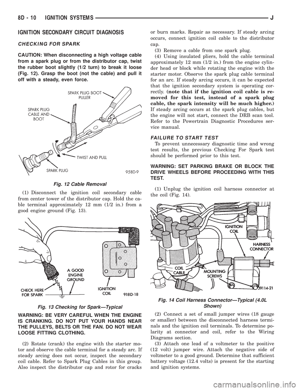
CAUTION: When disconnecting a high voltage cable
from a spark plug or from the distributor cap, twist
the rubber boot slightly (1/2 turn) to break it loose
(Fig. 12). Grasp the boot (not the cable) and pull it
off with a steady, even force.
(1) Disconnect the ignition coil secondary cable
from center tower of the distributor cap. Hold the ca-
ble terminal approximately 12 mm (1/2 in.) from a
good engine ground (Fig. 13).
WARNING: BE VERY CAREFUL WHEN THE ENGINE
IS CRANKING. DO NOT PUT YOUR HANDS NEAR
THE PULLEYS, BELTS OR THE FAN. DO NOT WEAR
LOOSE FITTING CLOTHING.
(2) Rotate (crank) the engine with the starter mo-
tor and observe the cable terminal for a steady arc. If
steady arcing does not occur, inspect the secondary
coil cable. Refer to Spark Plug Cables in this group.
Also inspect the distributor cap and rotor for cracksor burn marks. Repair as necessary. If steady arcing
occurs, connect ignition coil cable to the distributor
cap.
(3) Remove a cable from one spark plug.
(4) Using insulated pliers, hold the cable terminal
approximately 12 mm (1/2 in.) from the engine cylin-
der head or block while rotating the engine with the
starter motor. Observe the spark plug cable terminal
for an arc. If steady arcing occurs, it can be expected
that the ignition secondary system is operating cor-
rectly.(note that if the ignition coil cable is re-
moved for this test, instead of a spark plug
cable, the spark intensity will be much higher.)
If steady arcing occurs at the spark plug cables, but
the engine will not start, connect the DRB scan tool.
Refer to the Powertrain Diagnostic Procedures ser-
vice manual.
FAILURE TO START TEST
To prevent unnecessary diagnostic time and wrong
test results, the previous Checking For Spark test
should be performed prior to this test.
WARNING: SET PARKING BRAKE OR BLOCK THE
DRIVE WHEELS BEFORE PROCEEDING WITH THIS
TEST.
(1) Unplug the ignition coil harness connector at
the coil (Fig. 14).
(2) Connect a set of small jumper wires (18 gauge
or smaller) between the disconnected harness termi-
nals and the ignition coil terminals. To determine po-
larity at connector and coil, refer to the Wiring
Diagrams section.
(3) Attach one lead of a voltmeter to the positive
(12 volt) jumper wire. Attach the negative side of
voltmeter to a good ground. Determine that sufficient
battery voltage (12.4 volts) is present for the starting
and ignition systems.
Fig. 12 Cable Removal
Fig. 13 Checking for SparkÐTypical
Fig. 14 Coil Harness ConnectorÐTypical (4.0L
Shown)
8D - 10 IGNITION SYSTEMSJ
Page 335 of 2158
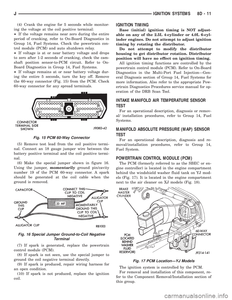
(4) Crank the engine for 5 seconds while monitor-
ing the voltage at the coil positive terminal:
²If the voltage remains near zero during the entire
period of cranking, refer to On-Board Diagnostics in
Group 14, Fuel Systems. Check the powertrain con-
trol module (PCM) and auto shutdown relay.
²If voltage is at or near battery voltage and drops
to zero after 1-2 seconds of cranking, check the cam-
shaft position sensor-to-PCM circuit. Refer to On-
Board Diagnostics in Group 14, Fuel Systems.
²If voltage remains at or near battery voltage dur-
ing the entire 5 seconds, turn the key off. Remove
the 60-way connector (Fig. 15) from the PCM. Check
60-way connector for any spread terminals.
(5) Remove test lead from the coil positive termi-
nal. Connect an 18 gauge jumper wire between the
battery positive terminal and the coil positive termi-
nal.
(6) Make the special jumper shown in figure 16.
Using the jumper,momentarilyground pin/cavity
number 19 of the PCM 60-way connector. A spark
should be generated at the coil cable when the
ground is removed.
(7) If spark is generated, replace the powertrain
control module (PCM).
(8) If spark is not seen, use the special jumper to
ground the coil negative terminal directly.
(9) If spark is produced, repair wiring harness for
an open condition.
(10) If spark is not produced, replace the ignition
coil.IGNITION TIMING
Base (initial) ignition timing is NOT adjust-
able on any of the 2.5L 4-cylinder or 4.0L 6-cyl-
inder engines. Do not attempt to adjust ignition
timing by rotating the distributor.
Do not attempt to modify the distributor
housing to get distributor rotation. Distributor
position will have no effect on ignition timing.
All ignition timing functions are controlled by the
powertrain control module (PCM). Refer to On-Board
Diagnostics in the Multi-Port Fuel InjectionÐGen-
eral Diagnosis section of Group 14, Fuel Systems for
more information. Also refer to the appropriate Pow-
ertrain Diagnostics Procedures service manual for op-
eration of the DRB Scan Tool.
INTAKE MANIFOLD AIR TEMPERATURE SENSOR
TEST
For an operational description, diagnosis or remov-
al/ installation procedures, refer to Group 14, Fuel
Systems.
MANIFOLD ABSOLUTE PRESSURE (MAP) SENSOR
TEST
For an operational description, diagnosis and re-
moval/installation procedures, refer to Group 14,
Fuel System.
POWERTRAIN CONTROL MODULE (PCM)
The PCM (formerly referred to as the SBEC or en-
gine controller) is located in the engine compartment
behind the windshield washer fluid tank on YJ mod-
els (Fig. 17). It is located in the engine compartment
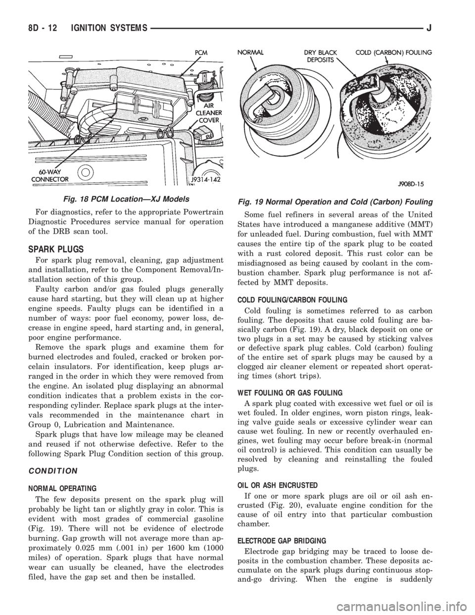
next to the air cleaner on XJ models (Fig. 18).
The ignition system is controlled by the PCM.
For removal and installation of this component, re-
fer to the Component Removal/Installation section of
this group.
Fig. 15 PCM 60-Way Connector
Fig. 16 Special Jumper Ground-to-Coil Negative
Terminal
Fig. 17 PCM LocationÐYJ Models
JIGNITION SYSTEMS 8D - 11
Page 336 of 2158
For diagnostics, refer to the appropriate Powertrain
Diagnostic Procedures service manual for operation
of the DRB scan tool.
SPARK PLUGS
For spark plug removal, cleaning, gap adjustment
and installation, refer to the Component Removal/In-
stallation section of this group.
Faulty carbon and/or gas fouled plugs generally
cause hard starting, but they will clean up at higher
engine speeds. Faulty plugs can be identified in a
number of ways: poor fuel economy, power loss, de-
crease in engine speed, hard starting and, in general,
poor engine performance.
Remove the spark plugs and examine them for
burned electrodes and fouled, cracked or broken por-
celain insulators. For identification, keep plugs ar-
ranged in the order in which they were removed from
the engine. An isolated plug displaying an abnormal
condition indicates that a problem exists in the cor-
responding cylinder. Replace spark plugs at the inter-
vals recommended in the maintenance chart in
Group 0, Lubrication and Maintenance.
Spark plugs that have low mileage may be cleaned
and reused if not otherwise defective. Refer to the
following Spark Plug Condition section of this group.
CONDITION
NORMAL OPERATING
The few deposits present on the spark plug will
probably be light tan or slightly gray in color. This is
evident with most grades of commercial gasoline
(Fig. 19). There will not be evidence of electrode
burning. Gap growth will not average more than ap-
proximately 0.025 mm (.001 in) per 1600 km (1000
miles) of operation. Spark plugs that have normal
wear can usually be cleaned, have the electrodes
filed, have the gap set and then be installed.Some fuel refiners in several areas of the United
States have introduced a manganese additive (MMT)
for unleaded fuel. During combustion, fuel with MMT
causes the entire tip of the spark plug to be coated
with a rust colored deposit. This rust color can be
misdiagnosed as being caused by coolant in the com-
bustion chamber. Spark plug performance is not af-
fected by MMT deposits.
COLD FOULING/CARBON FOULING
Cold fouling is sometimes referred to as carbon
fouling. The deposits that cause cold fouling are ba-
sically carbon (Fig. 19). A dry, black deposit on one or
two plugs in a set may be caused by sticking valves
or defective spark plug cables. Cold (carbon) fouling
of the entire set of spark plugs may be caused by a
clogged air cleaner element or repeated short operat-
ing times (short trips).
WET FOULING OR GAS FOULING
A spark plug coated with excessive wet fuel or oil is
wet fouled. In older engines, worn piston rings, leak-
ing valve guide seals or excessive cylinder wear can
cause wet fouling. In new or recently overhauled en-
gines, wet fouling may occur before break-in (normal
oil control) is achieved. This condition can usually be
resolved by cleaning and reinstalling the fouled
plugs.
OIL OR ASH ENCRUSTED
If one or more spark plugs are oil or oil ash en-
crusted (Fig. 20), evaluate engine condition for the
cause of oil entry into that particular combustion
chamber.
ELECTRODE GAP BRIDGING
Electrode gap bridging may be traced to loose de-
posits in the combustion chamber. These deposits ac-
cumulate on the spark plugs during continuous stop-
and-go driving. When the engine is suddenly
Fig. 18 PCM LocationÐXJ ModelsFig. 19 Normal Operation and Cold (Carbon) Fouling
8D - 12 IGNITION SYSTEMSJ
Page 337 of 2158
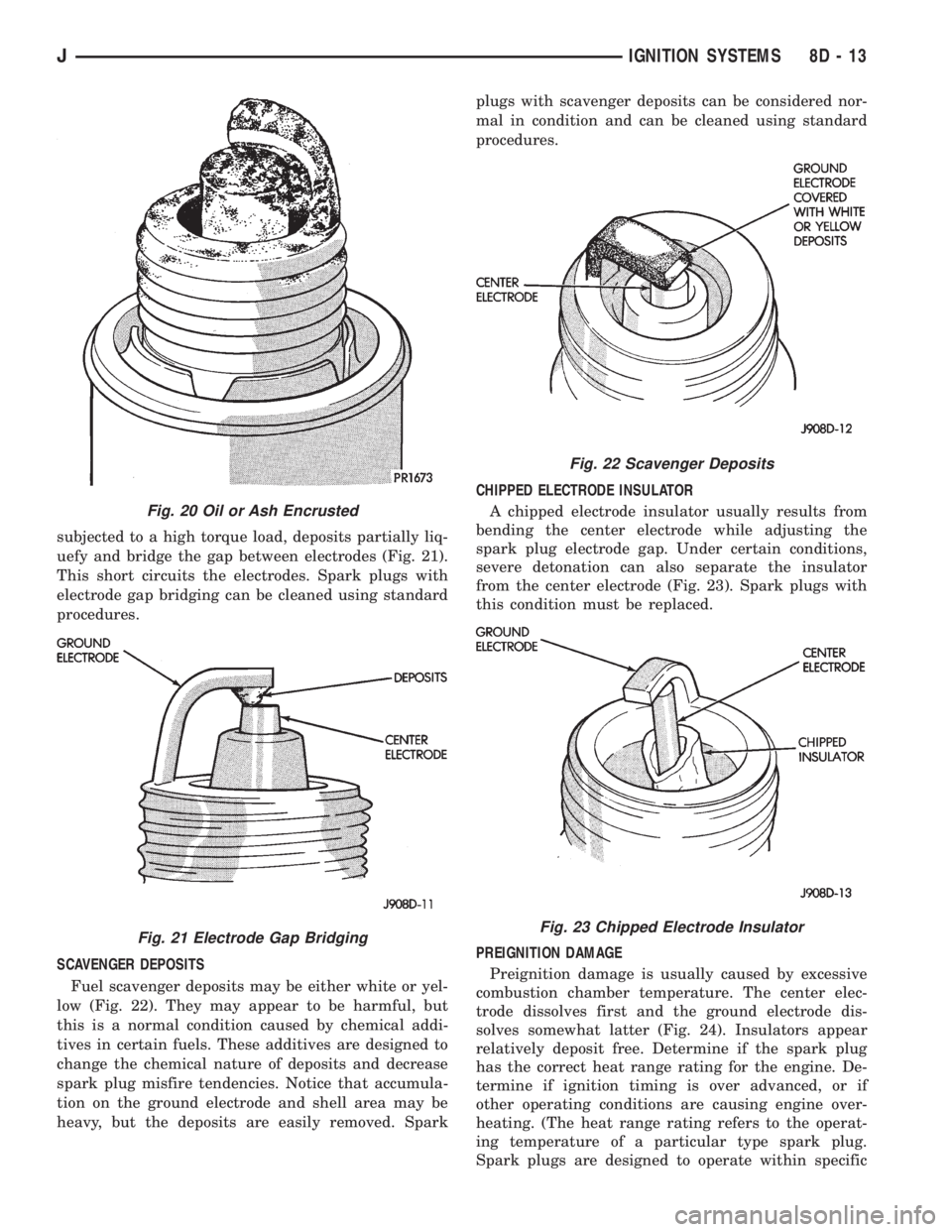
subjected to a high torque load, deposits partially liq-
uefy and bridge the gap between electrodes (Fig. 21).
This short circuits the electrodes. Spark plugs with
electrode gap bridging can be cleaned using standard
procedures.
SCAVENGER DEPOSITS
Fuel scavenger deposits may be either white or yel-
low (Fig. 22). They may appear to be harmful, but
this is a normal condition caused by chemical addi-
tives in certain fuels. These additives are designed to
change the chemical nature of deposits and decrease
spark plug misfire tendencies. Notice that accumula-
tion on the ground electrode and shell area may be
heavy, but the deposits are easily removed. Sparkplugs with scavenger deposits can be considered nor-
mal in condition and can be cleaned using standard
procedures.
CHIPPED ELECTRODE INSULATOR
A chipped electrode insulator usually results from
bending the center electrode while adjusting the
spark plug electrode gap. Under certain conditions,
severe detonation can also separate the insulator
from the center electrode (Fig. 23). Spark plugs with
this condition must be replaced.
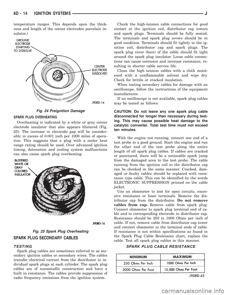
PREIGNITION DAMAGE
Preignition damage is usually caused by excessive
combustion chamber temperature. The center elec-
trode dissolves first and the ground electrode dis-
solves somewhat latter (Fig. 24). Insulators appear
relatively deposit free. Determine if the spark plug
has the correct heat range rating for the engine. De-
termine if ignition timing is over advanced, or if
other operating conditions are causing engine over-
heating. (The heat range rating refers to the operat-
ing temperature of a particular type spark plug.
Spark plugs are designed to operate within specific
Fig. 20 Oil or Ash Encrusted
Fig. 21 Electrode Gap Bridging
Fig. 22 Scavenger Deposits
Fig. 23 Chipped Electrode Insulator
JIGNITION SYSTEMS 8D - 13
Page 338 of 2158
temperature ranges. This depends upon the thick-
ness and length of the center electrodes porcelain in-
sulator.)
SPARK PLUG OVERHEATING
Overheating is indicated by a white or gray center
electrode insulator that also appears blistered (Fig.
25). The increase in electrode gap will be consider-
ably in excess of 0.001 inch per 1000 miles of opera-
tion. This suggests that a plug with a cooler heat
range rating should be used. Over advanced ignition
timing, detonation and cooling system malfunctions
can also cause spark plug overheating.
SPARK PLUG SECONDARY CABLES
TESTING
Spark plug cables are sometimes referred to as sec-
ondary ignition cables or secondary wires. The cables
transfer electrical current from the distributor to in-
dividual spark plugs at each cylinder. The spark plug
cables are of nonmetallic construction and have a
built in resistance. The cables provide suppression of
radio frequency emissions from the ignition system.Check the high-tension cable connections for good
contact at the ignition coil, distributor cap towers
and spark plugs. Terminals should be fully seated.
The terminals and spark plug covers should be in
good condition. Terminals should fit tightly to the ig-
nition coil, distributor cap and spark plugs. The
spark plug cover (boot) of the cable should fit tight
around the spark plug insulator. Loose cable connec-
tions can cause corrosion and increase resistance, re-
sulting in shorter cable service life.
Clean the high tension cables with a cloth moist-
ened with a nonflammable solvent and wipe dry.
Check for brittle or cracked insulation.
When testing secondary cables for damage with an
oscilloscope, follow the instructions of the equipment
manufacturer.
If an oscilloscope is not available, spark plug cables
may be tested as follows:
CAUTION: Do not leave any one spark plug cable
disconnected for longer than necessary during test-
ing. This may cause possible heat damage to the
catalytic converter. Total test time must not exceed
ten minutes.
With the engine not running, connect one end of a
test probe to a good ground. Start the engine and run
the other end of the test probe along the entire
length of all spark plug cables. If cables are cracked
or punctured, there will be a noticeable spark jump
from the damaged area to the test probe. The cable
running from the ignition coil to the distributor cap
can be checked in the same manner. Cracked, dam-
aged or faulty cables should be replaced with resis-
tance type cable. This can be identified by the words
ELECTRONIC SUPPRESSION printed on the cable
jacket.
Use an ohmmeter to test for open circuits, exces-
sive resistance or loose terminals. Remove the dis-
tributor cap from the distributor.Do not remove
cables from cap.Remove cable from spark plug.
Connect ohmmeter to spark plug terminal end of ca-
ble and to corresponding electrode in distributor cap.
Resistance should be 250 to 1000 Ohms per inch of
cable. If not, remove cable from distributor cap tower
and connect ohmmeter to the terminal ends of cable.
If resistance is not within specifications as found in
the Spark Plug Cable Resistance chart, replace the
cable. Test all spark plug cables in this manner.
Fig. 24 Preignition Damage
Fig. 25 Spark Plug Overheating
SPARK PLUG CABLE RESISTANCE
8D - 14 IGNITION SYSTEMSJ
Page 339 of 2158
To test ignition coil-to-distributor cap cable, do not
remove the cable from the cap. Connect ohmmeter to
rotor button (center contact) of distributor cap and
terminal at ignition coil end of cable. If resistance is
not within specifications as found in the Spark Plug
Cable Resistance chart, remove the cable from the
distributor cap. Connect the ohmmeter to the termi-
nal ends of the cable. If resistance is not within spec-
ifications as found in the Spark Plug Cable
Resistance chart, replace the cable. Inspect the igni-
tion coil tower for cracks, burns or corrosion.
For removal and installation of spark plug cables,
refer to Spark Plug Secondary Cables in the Compo-
nent Removal/Installation section.
THROTTLE POSITION SENSOR TEST
For an operational description, diagnosis and re-
moval/installation procedures, refer to Group 14,
Fuel System.
OXYGEN (O2S) SENSOR TESTS
For an operational description, diagnosis or remov-
al/ installation procedures, refer to Group 14, Fuel
Systems.
ON-BOARD DIAGNOSTICS
FOR CERTAIN IGNITION SYSTEM
COMPONENTS
The powertrain control module (PCM) performs an
On-Board Diagnostic (OBD) check for certain ignition
system components on all vehicles. This is done by
setting a diagnostic trouble code (DTC).
A DTC can be obtained in two different ways. One
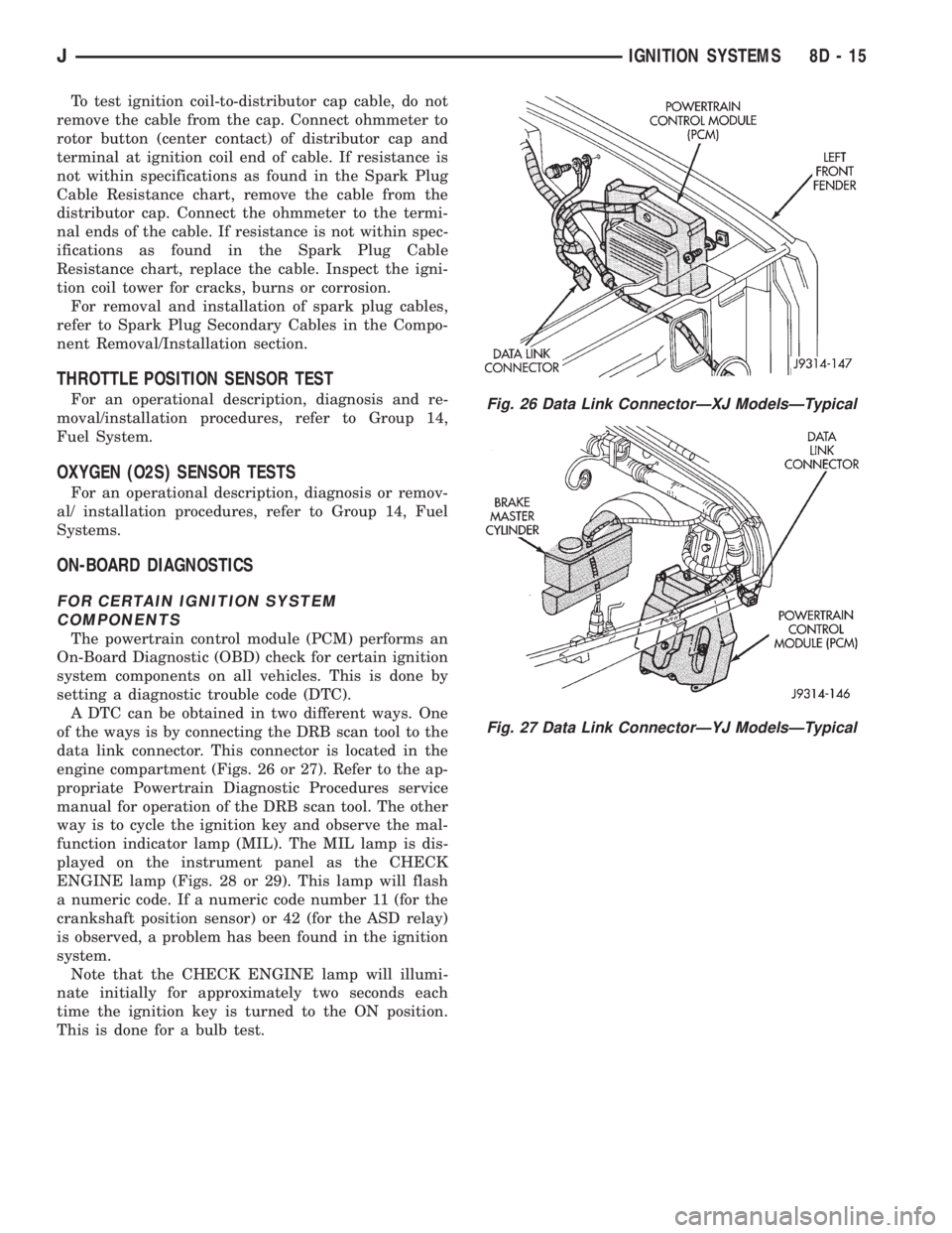
of the ways is by connecting the DRB scan tool to the
data link connector. This connector is located in the
engine compartment (Figs. 26 or 27). Refer to the ap-
propriate Powertrain Diagnostic Procedures service
manual for operation of the DRB scan tool. The other
way is to cycle the ignition key and observe the mal-
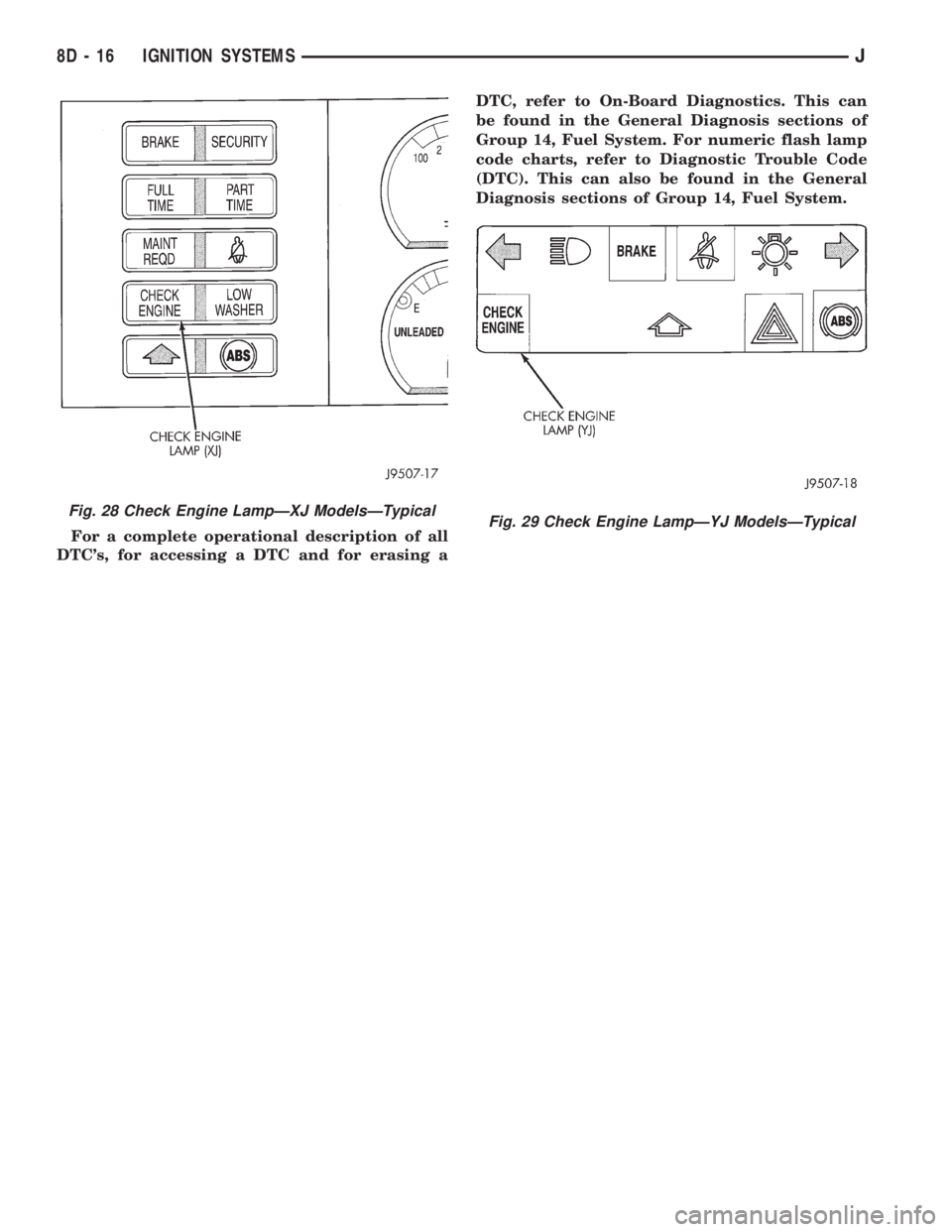
function indicator lamp (MIL). The MIL lamp is dis-
played on the instrument panel as the CHECK
ENGINE lamp (Figs. 28 or 29). This lamp will flash
a numeric code. If a numeric code number 11 (for the
crankshaft position sensor) or 42 (for the ASD relay)
is observed, a problem has been found in the ignition
system.
Note that the CHECK ENGINE lamp will illumi-
nate initially for approximately two seconds each
time the ignition key is turned to the ON position.
This is done for a bulb test.
Fig. 26 Data Link ConnectorÐXJ ModelsÐTypical
Fig. 27 Data Link ConnectorÐYJ ModelsÐTypical
JIGNITION SYSTEMS 8D - 15
Page 340 of 2158
For a complete operational description of all
DTC's, for accessing a DTC and for erasing aDTC, refer to On-Board Diagnostics. This can
be found in the General Diagnosis sections of
Group 14, Fuel System. For numeric flash lamp
code charts, refer to Diagnostic Trouble Code
(DTC). This can also be found in the General
Diagnosis sections of Group 14, Fuel System.
Fig. 28 Check Engine LampÐXJ ModelsÐTypicalFig. 29 Check Engine LampÐYJ ModelsÐTypical
8D - 16 IGNITION SYSTEMSJ