2.5 engine JEEP YJ 1995 Service And Owner's Guide
[x] Cancel search | Manufacturer: JEEP, Model Year: 1995, Model line: YJ, Model: JEEP YJ 1995Pages: 2158, PDF Size: 81.9 MB
Page 348 of 2158
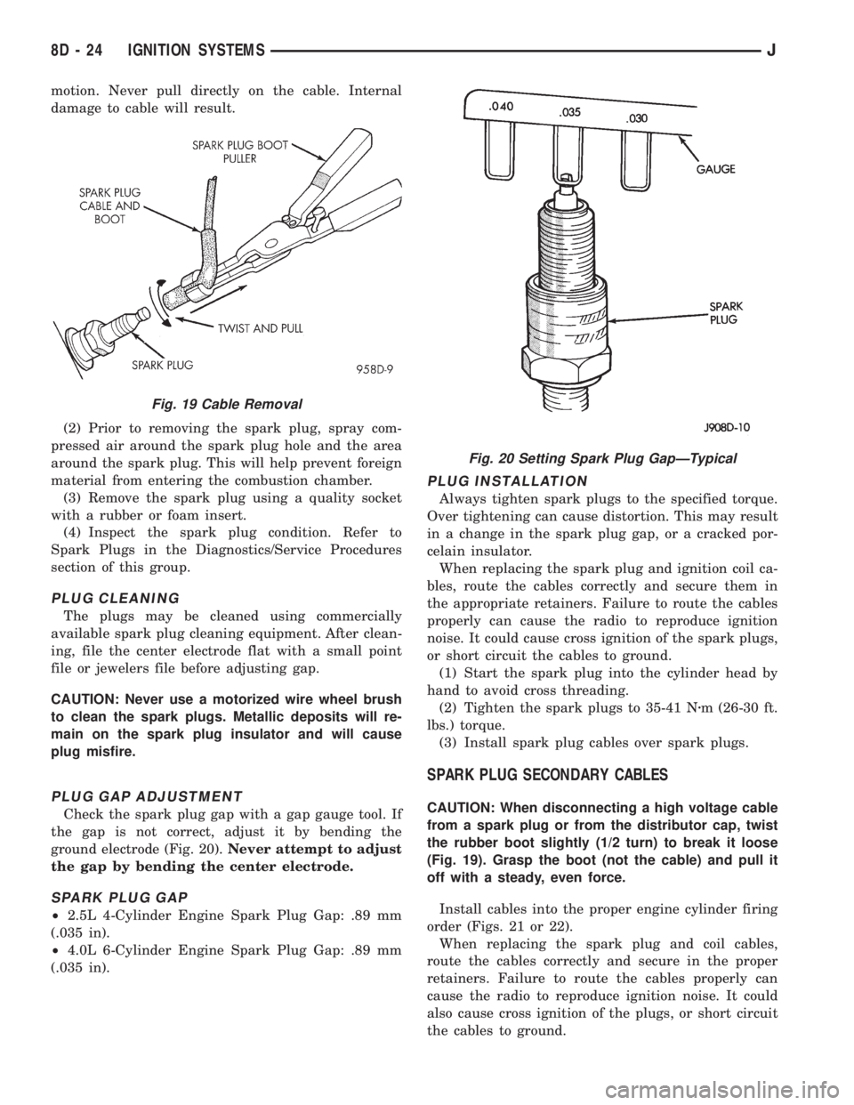
motion. Never pull directly on the cable. Internal
damage to cable will result.
(2) Prior to removing the spark plug, spray com-
pressed air around the spark plug hole and the area
around the spark plug. This will help prevent foreign
material from entering the combustion chamber.
(3) Remove the spark plug using a quality socket
with a rubber or foam insert.
(4) Inspect the spark plug condition. Refer to
Spark Plugs in the Diagnostics/Service Procedures
section of this group.
PLUG CLEANING
The plugs may be cleaned using commercially
available spark plug cleaning equipment. After clean-
ing, file the center electrode flat with a small point
file or jewelers file before adjusting gap.
CAUTION: Never use a motorized wire wheel brush
to clean the spark plugs. Metallic deposits will re-
main on the spark plug insulator and will cause
plug misfire.
PLUG GAP ADJUSTMENT
Check the spark plug gap with a gap gauge tool. If
the gap is not correct, adjust it by bending the
ground electrode (Fig. 20).Never attempt to adjust
the gap by bending the center electrode.
SPARK PLUG GAP
²2.5L 4-Cylinder Engine Spark Plug Gap: .89 mm
(.035 in).
²4.0L 6-Cylinder Engine Spark Plug Gap: .89 mm
(.035 in).
PLUG INSTALLATION
Always tighten spark plugs to the specified torque.
Over tightening can cause distortion. This may result
in a change in the spark plug gap, or a cracked por-
celain insulator.
When replacing the spark plug and ignition coil ca-
bles, route the cables correctly and secure them in
the appropriate retainers. Failure to route the cables
properly can cause the radio to reproduce ignition
noise. It could cause cross ignition of the spark plugs,
or short circuit the cables to ground.
(1) Start the spark plug into the cylinder head by
hand to avoid cross threading.
(2) Tighten the spark plugs to 35-41 Nzm (26-30 ft.
lbs.) torque.
(3) Install spark plug cables over spark plugs.
SPARK PLUG SECONDARY CABLES
CAUTION: When disconnecting a high voltage cable
from a spark plug or from the distributor cap, twist
the rubber boot slightly (1/2 turn) to break it loose
(Fig. 19). Grasp the boot (not the cable) and pull it
off with a steady, even force.
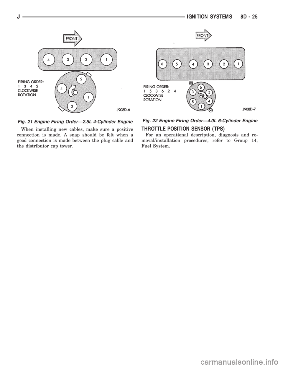
Install cables into the proper engine cylinder firing
order (Figs. 21 or 22).
When replacing the spark plug and coil cables,
route the cables correctly and secure in the proper
retainers. Failure to route the cables properly can
cause the radio to reproduce ignition noise. It could
also cause cross ignition of the plugs, or short circuit
the cables to ground.
Fig. 19 Cable Removal
Fig. 20 Setting Spark Plug GapÐTypical
8D - 24 IGNITION SYSTEMSJ
Page 349 of 2158
When installing new cables, make sure a positive
connection is made. A snap should be felt when a
good connection is made between the plug cable and
the distributor cap tower.THROTTLE POSITION SENSOR (TPS)
For an operational description, diagnosis and re-
moval/installation procedures, refer to Group 14,
Fuel System.
Fig. 22 Engine Firing OrderÐ4.0L 6-Cylinder EngineFig. 21 Engine Firing OrderÐ2.5L 4-Cylinder Engine
JIGNITION SYSTEMS 8D - 25
Page 356 of 2158
SPECIFICATIONS
GENERAL INFORMATION
The following specifications are published from the
latest information available at the time of publica-
tion.If anything differs between the specifica-
tions found on the Vehicle Emission Control
Information (VECI) label and the following
specifications, use specifications on VECI label.
The VECI label is located in the engine compart-
ment.
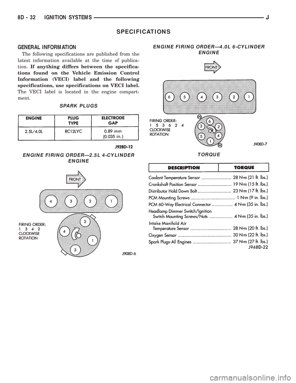
SPARK PLUGS
ENGINE FIRING ORDERÐ2.5L 4-CYLINDER
ENGINE
ENGINE FIRING ORDERÐ4.0L 6-CYLINDER
ENGINE
TORQUE
8D - 32 IGNITION SYSTEMSJ
Page 362 of 2158
(5) Probe cavity B1 of cluster connector A. Check
for continuity to a good ground. There should be no
continuity. If OK, go to next step. If not OK, repair
short circuit as required.
(6) Still probing cavity B1 of cluster connector A,
check for continuity to cavity B of sending unit body
half connector. There should be continuity. If OK, re-
place gauge. If not OK, repair open circuit as re-
quired.
OIL PRESSURE GAUGE
The diagnosis found here addresses an inoperative
gauge condition. If the problem being diagnosed is re-
lated to gauge accuracy, be certain to confirm that
problem is with gauge and not with engine oiling sys-
tem performance. Actual engine oil pressure should
be checked with a test gauge and compared to gauge
readings before you proceed with gauge diagnosis.
Refer to Group 9 - Engines for more information.
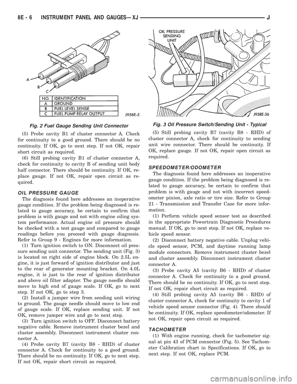
(1) Turn ignition switch to ON. Disconnect oil pres-
sure sending unit connector. The sending unit (Fig. 3)
is located on right side of engine block. On 2.5L en-
gine, it is just forward of ignition distributor and just
to the rear of generator mounting bracket. On 4.0L
engine, it is just to the rear of ignition distributor
and above oil filter adapter. The gauge needle should
move to high end of gauge scale. If OK, go to next
step. If not OK, go to step 3.
(2) Install a jumper wire from sending unit wiring
to ground. The gauge needle should move to low end
of gauge scale. If OK, replace sending unit. If not
OK, remove jumper wire and go to next step.
(3) Turn ignition switch to OFF. Disconnect battery
negative cable. Remove instrument cluster bezel and
cluster assembly. Disconnect instrument cluster con-
nector A.
(4) Probe cavity B7 (cavity B8 - RHD) of cluster
connector A. Check for continuity to a good ground.
There should be no continuity. If OK, go to next step.
If not OK, repair short circuit as required.(5) Still probing cavity B7 (cavity B8 - RHD) of
cluster connector A, check for continuity to sending
unit wire connector. There should be continuity. If
OK, replace gauge. If not OK, repair open circuit as
required.
SPEEDOMETER/ODOMETER
The diagnosis found here addresses an inoperative
gauge condition. If the problem being diagnosed is re-
lated to gauge accuracy, be certain to confirm that
problem is with gauge and not with incorrect speed-
ometer pinion, axle ratio or tire size. Refer to Group
21 - Transmission and Transfer Case for more infor-
mation.
(1) Perform vehicle speed sensor test as described
in the appropriate Powertrain Diagnostic Procedures
manual. If OK, go to next step. If not OK, replace ve-
hicle speed sensor.
(2) Disconnect battery negative cable. Unplug vehi-
cle speed sensor, PCM, and daytime running lamp
module connectors. Remove instrument cluster bezel
and cluster assembly. Disconnect instrument cluster
connector A.
(3) Probe cavity A5 (cavity B6 - RHD) of cluster
connector A. Check for continuity to a good ground.
There should be no continuity. If OK, go to next step.
If not OK, repair short circuit as required.
(4) Still probing cavity A5 (cavity B6 - RHD) of
cluster connector A, check for continuity to cavity 1 of
vehicle speed sensor connector (Fig. 4). There should
be continuity. If OK, replace speedometer/odometer. If
not OK, repair open circuit as required.
TACHOMETER
(1) With engine running, check for tachometer sig-
nal at pin 43 of PCM connector (Fig. 5). See Tachom-
eter Calibration chart in Specifications. If OK, go to
next step. If not OK, replace PCM.
Fig. 2 Fuel Gauge Sending Unit ConnectorFig. 3 Oil Pressure Switch/Sending Unit - Typical
8E - 6 INSTRUMENT PANEL AND GAUGESÐXJJ
Page 370 of 2158
(2) Disconnect battery negative cable. Remove in-
strument cluster bezel and cluster assembly. Unplug
cluster connector A. Connect battery negative cable.
Turn headlamps on and select high beam. Check for
battery voltage at cavity A4 of cluster connector A. If
OK, replace indicator bulb. If not OK, repair circuit
to headlamp dimmer (multi-function) switch as re-
quired.
LOW FUEL WARNING LAMP
(1) Check that fuel gauge is operating as designed.
See Fuel Gauge Calibration chart in Specifications. If
OK, go to next step. If not OK, see Fuel Gauge in
this section for diagnosis.
(2) With at least 10 gallons of fuel in fuel tank, un-
plug fuel tank sending unit connector. Turn ignition
switch to ON and wait 10 seconds. Lamp (LED)
should light. Reconnect fuel tank sending unit and
wait 20 seconds. Lamp (LED) should go off. If not
OK, replace low fuel warning lamp module.
LOW OIL PRESSURE WARNING LAMP
The diagnosis found here addresses an inoperative
lamp condition. If the problem being diagnosed is re-
lated to lamp accuracy, be certain to confirm that
problem is with lamp and not with engine oiling sys-
tem. Actual engine oil pressure should be checked
with a test gauge before you proceed with lamp diag-
nosis. Refer to Group 9 - Engines for more informa-
tion.
(1) Turn ignition switch to ON. Lamp should light.
Start engine. Lamp should go off. If not OK, turn en-
gine off and go to next step.
(2) Unplug connector at oil pressure switch (Fig.
3). The switch is located on right side of engine block.
On 2.5L engine, it is just forward of ignition distrib-
utor and just to the rear of generator mounting
bracket. On 4.0L engine, it is just to the rear of igni-
tion distributor and above oil filter adapter. Install a
jumper wire from connector to a good ground. Turn
ignition switch to ON. Lamp should light. Unplug
jumper wire. Lamp should go out. If OK, replace oil
pressure switch. If not OK, go to next step.
(3) Turn ignition switch to OFF. Disconnect battery
negative cable. Remove instrument cluster bezel and
cluster assembly. Install a jumper wire from cavity
B7 (cavity B8 - RHD) of cluster connector A to a good
ground. Connect battery negative cable and turn ig-
nition switch to ON. Lamp should light. If OK, go to
next step. If not OK, replace lamp bulb.
(4) Turn ignition switch to OFF. Disconnect battery
negative cable. Unplug instrument cluster connector
A. Check continuity between cavity B7 (cavity B8 -
RHD) of cluster connector A and a good ground.
There should be no continuity. If OK, go to next step.
If not OK, repair short circuit as required.
(5) Check continuity between cavity B7 (cavity B8
- RHD) of cluster connector A and oil pressure switchconnector. There should be continuity. If not OK, re-
pair open circuit as required.
LOW WASHER FLUID WARNING LAMP
(1) Unplug washer fluid level switch connector.
Turn ignition switch to ON. Check for battery voltage
at connector cavity A. If OK, turn ignition switch to
OFF and go to next step. If not OK, repair open cir-
cuit to fuse F6 in PDC.
(2) Install a jumper wire from cavity A to cavity B
of washer fluid level switch connector. Turn ignition
switch to ON. Lamp should light. Unplug jumper and
lamp should go OFF. If OK, replace washer fluid
level switch. If not OK, go to next step.
(3) Turn ignition switch to OFF. Disconnect battery
negative cable. Remove instrument cluster bezel and
cluster assembly. Unplug instrument cluster (tell-
tale) connector B. Check continuity between cavity 16
(cavity 1 - RHD) of cluster connector B and a good
ground. There should be continuity. If OK, plug clus-
ter connector B back into cluster and go to next step.
If not OK, repair open circuit to ground as required.
(4) Connect battery negative cable. Install a
jumper wire from a 12-volt battery feed to cavity 1
(cavity 16 - RHD) of cluster connector B. Lamp
should light. If OK, go to next step. If not OK, re-
place bulb.
(5) Disconnect battery negative cable. Unplug clus-
ter connector B. Check continuity between cavity 1
(cavity 16 - RHD) of cluster connector B and a good
ground. There should be no continuity. If OK, go to
next step. If not OK, repair short circuit to switch as
required.
(6) Check continuity between cavity 1 (cavity 16 -
RHD) of cluster connector B and cavity B of washer
fluid level switch connector. There should be continu-
ity. If not OK, repair open circuit to switch as re-
quired.
MALFUNCTION INDICATOR LAMP
The diagnosis found here addresses an inoperative
lamp condition. If the lamp comes on and stays on
with engine running, refer to Group 14 - Fuel System
for diagnosis. If no fuel or emission system problem
is found, the following procedure will help locate a
short or open in the lamp circuit.
(1) Disconnect battery negative cable. Unplug PCM
connector. Install a jumper wire from cavity 32 of
PCM connector (Fig. 5) to a good ground. Connect
battery negative cable. Turn ignition switch to ON.
Lamp should light. Remove jumper wire and lamp
should go OFF. If OK, refer to Powertrain Diagnostic
Procedures to check PCM. If not OK, go to next step.
(2) Turn ignition switch to OFF. Disconnect battery
negative cable. Remove instrument cluster bezel and
cluster assembly. Install a jumper wire from cavity 2
(cavity 15 - RHD) of cluster (tell-tale) connector B to
a good ground. Connect battery negative cable. Turn
8E - 14 INSTRUMENT PANEL AND GAUGESÐXJJ
Page 384 of 2158
continuity. If OK, go to next step. If not OK, repair
circuit to ground as required.
(4) Remove center instrument cluster bezel and
gauge package cluster assembly. Disconnect cluster
connector.
(5) Probe cavity 6 of cluster connector. Check for
continuity to a good ground. There should be no con-
tinuity. If OK, go to next step. If not OK, repair short
circuit as required.
(6) Still probing cavity 6 of cluster connector, check
for continuity to cavity 2 of sending unit wiring body
half connector. There should be continuity. If OK, re-
place gauge. If not OK, repair open circuit as re-
quired.
OIL PRESSURE GAUGE
The diagnosis found here addresses an inoperative
gauge condition. If the problem being diagnosed is re-
lated to gauge accuracy, be certain to confirm that
problem is with gauge and not with engine oiling sys-
tem performance. Actual engine oil pressure should
be checked with a test gauge and compared to gauge
readings before you proceed with gauge diagnosis.
Refer to Group 9 - Engines for more information.
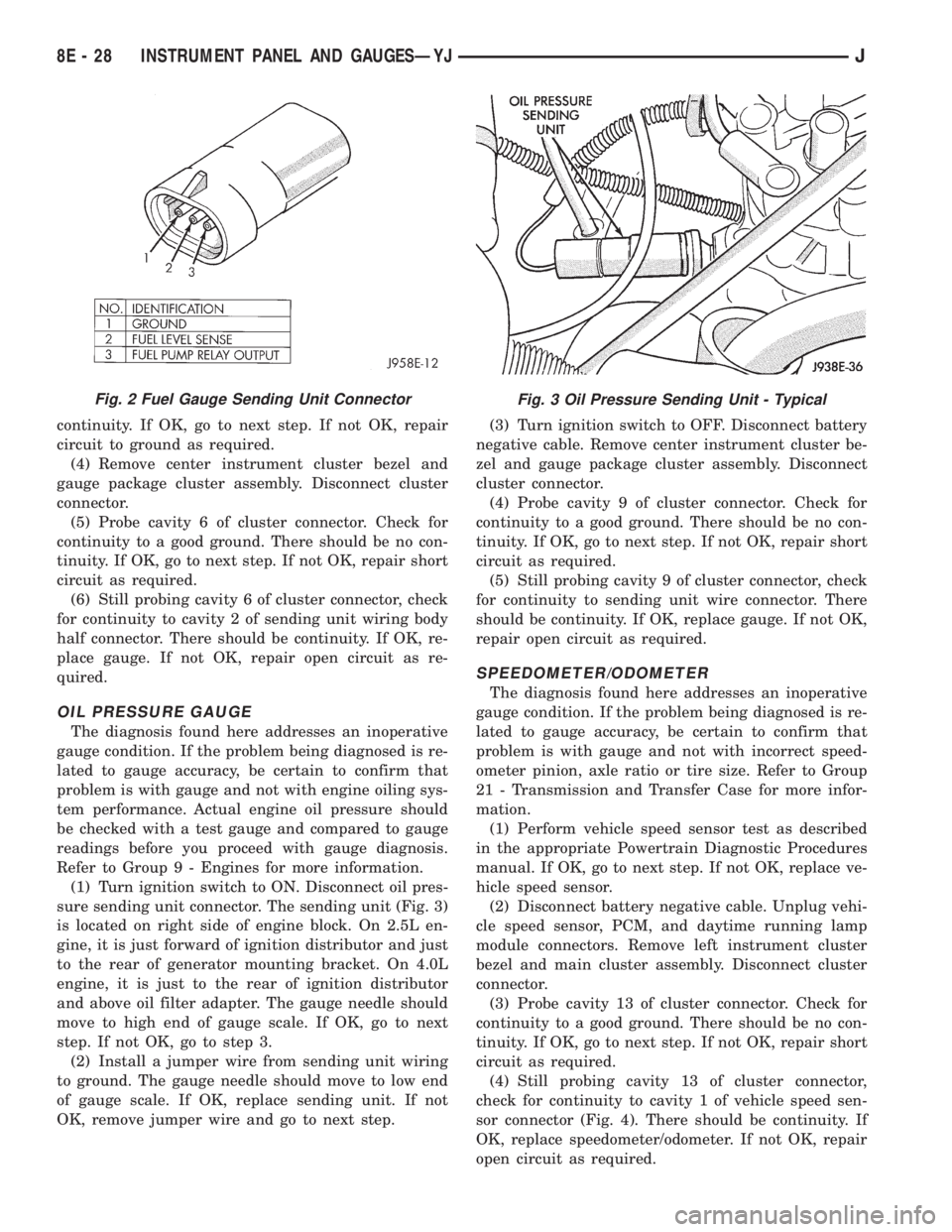
(1) Turn ignition switch to ON. Disconnect oil pres-
sure sending unit connector. The sending unit (Fig. 3)
is located on right side of engine block. On 2.5L en-
gine, it is just forward of ignition distributor and just
to the rear of generator mounting bracket. On 4.0L
engine, it is just to the rear of ignition distributor
and above oil filter adapter. The gauge needle should
move to high end of gauge scale. If OK, go to next
step. If not OK, go to step 3.
(2) Install a jumper wire from sending unit wiring
to ground. The gauge needle should move to low end
of gauge scale. If OK, replace sending unit. If not
OK, remove jumper wire and go to next step.(3) Turn ignition switch to OFF. Disconnect battery
negative cable. Remove center instrument cluster be-
zel and gauge package cluster assembly. Disconnect
cluster connector.
(4) Probe cavity 9 of cluster connector. Check for
continuity to a good ground. There should be no con-
tinuity. If OK, go to next step. If not OK, repair short
circuit as required.
(5) Still probing cavity 9 of cluster connector, check
for continuity to sending unit wire connector. There
should be continuity. If OK, replace gauge. If not OK,
repair open circuit as required.
SPEEDOMETER/ODOMETER
The diagnosis found here addresses an inoperative
gauge condition. If the problem being diagnosed is re-
lated to gauge accuracy, be certain to confirm that
problem is with gauge and not with incorrect speed-
ometer pinion, axle ratio or tire size. Refer to Group
21 - Transmission and Transfer Case for more infor-
mation.
(1) Perform vehicle speed sensor test as described
in the appropriate Powertrain Diagnostic Procedures
manual. If OK, go to next step. If not OK, replace ve-
hicle speed sensor.
(2) Disconnect battery negative cable. Unplug vehi-
cle speed sensor, PCM, and daytime running lamp
module connectors. Remove left instrument cluster
bezel and main cluster assembly. Disconnect cluster
connector.
(3) Probe cavity 13 of cluster connector. Check for
continuity to a good ground. There should be no con-
tinuity. If OK, go to next step. If not OK, repair short
circuit as required.
(4) Still probing cavity 13 of cluster connector,
check for continuity to cavity 1 of vehicle speed sen-
sor connector (Fig. 4). There should be continuity. If
OK, replace speedometer/odometer. If not OK, repair
open circuit as required.
Fig. 2 Fuel Gauge Sending Unit ConnectorFig. 3 Oil Pressure Sending Unit - Typical
8E - 28 INSTRUMENT PANEL AND GAUGESÐYJJ
Page 581 of 2158
CHARGING SYSTEM
CHARGING SYSTEM
The charging system is an integral part of the bat-
tery and starting systems. Because all these systems
work in conjunction, diagnose and test them together.
Circuit A11 connects to the generator output termi-
nal and splices to fuse 1 and fuse 8 in the Power Dis-
tribution Center (PDC). Circuit A0 connects the
battery to the PDC.
Circuit Z0 provides ground for the generator. Cir-
cuit Z0 attaches to the right rear of the engine.
When the ignition switch is in either the START or
RUN positions, it connects circuit A1 from fuse 6 in
the PDC to circuit A21. Circuit A21 splices to supply
current to the coil side of the automatic shut down
(ASD) relay. The powertrain control module (PCM)
provides ground for the relay on circuit K51. Circuit
K51 connects to cavity 51 of the PCM.
When the PCM grounds the ASD relay, contacts in-
side the relay close and connect circuit A18 from fuse
14 in the PDC to circuit A142. Circuit A142 splices to
the generator field terminal.
The PCM has an internal voltage regulator that
controls generator output. The PCM controls the gen-
erator field on circuit K20. Circuit K20 connects to
PCM cavity 20.
When the engine operates and there is current in
the generator field, the generator produces a B+ volt-
age. The generator supplies B+ voltage to the battery
through the A11 and A0 circuits.
HELPFUL INFORMATION
²If the vehicle is equipped with a 2.5L engine, cir-
cuit Z0 also connects to the battery.
²Circuit A14 from fuse 2 in the PDC supplies volt-
age to the fuse block for fuse 14.
²The ignition switch also connects circuit A1 with
circuits A41, A38, and A48.
²Circuit A21 also splices to power fuse 17 in the
fuse block.
²Circuit A21 also powers the coil side of the fuel
pump relay.
²The ASD relay supplies battery voltage for the fuel
injectors, ignition coil, and the heated oxygen sensor.
The fuel pump relay powers the fuel pump module.
²Circuit K51 also provides ground for the coil side
of the fuel pump relay.
DIAGRAM INDEX
Component Page
Battery (2.5L)...........................8W-20-2
Battery (4.0L)...........................8W-20-3
PDC Fuse 1 (2.5L).......................8W-20-2
PDC Fuse 1 (4.0L).......................8W-20-3
PDC Fuse 9 (2.5L).......................8W-20-2
PDC Fuse 9 (4.0L).......................8W-20-3
Generator (2.5L).........................8W-20-2
Generator (4.0L).........................8W-20-3
Powertrain Control Module (2.5L)..............8W-20-2
Powertrain Control Module (4.0L)..............8W-20-3
J8W-20 CHARGING SYSTEMÐXJ VEHICLES 8W - 20 - 1
Page 585 of 2158
STARTING SYSTEM
INDEX
page page
Diagram Index............................ 1Starting System........................... 1
STARTING SYSTEM
AUTOMATIC TRANSMISSIONS
Circuit A0 from the battery is double crimped at
the positive battery post. One branch of circuit A0
(battery positive cable) connects to the engine starter
motor. The other A0 branch supplies voltage to the
bus bar in the power distribution center (PDC).
Fuse 7 in the PDC supplies battery voltage to the
contact side of the engine starter motor relay on cir-
cuit A4. When the coil side of the engine starter mo-
tor relay energizes, the contacts close and connect
circuit A4 to circuit T40. Circuit T40 supplies battery
voltage to the starter motor solenoid.
The ignition switch supplies battery voltage to the
coil side of the starter motor relay on circuit A41
when the key is moved to the START position and
the PARK/NEUTRAL position switch is closed.
Ground for the coil side of the starter motor relay is
supplied by the case grounded PARK/NEUTRAL po-
sition switch. Circuit T41 connects the coil side of the
relay to the PARK/NEUTRAL position switch.
When the starter motor relay energizes and the
contacts close, circuit T40 supplies battery voltage to
the starter motor solenoid. Circuit A0 from the bat-
tery supplies voltage to the starter motor when the
solenoid energizes.
MANUAL TRANSMISSIONS
Circuit A0 from the battery is double crimped at
the positive battery post. One branch of circuit A0
(battery positive cable) connects to the battery
starter motor. The other A0 branch supplies voltage
to the buss bar in the power distribution center
(PDC).
Fuse 7 in the PDC supplies battery voltage to the
contact side of the engine starter motor relay on cir-
cuit A4. When the coil side of the engine starter mo-
tor relay energizes, the contacts close and connect
circuit A4 to circuit T40. Circuit T40 supplies battery
voltage to the starter motor solenoid.The ignition switch supplies battery voltage to the
coil side of the starter motor relay on circuit A41
when the key is moved to the START position. Cir-
cuit Z12 provides ground for the coil side of the relay.
When the starter motor relay energizes and the
contacts close, circuit T40 supplies battery voltage to
the starter motor solenoid. Circuit A0 from the bat-
tery supplies voltage to the starter motor when the
solenoid energizes.
HELPFUL INFORMATION
²The Park/Neutral switch closes when the trans-
mission is in either the PARK or NEUTRAL posi-
tions.
²Circuit T41 also connects to cavity 30 of the pow-
ertrain control module (PCM). This input tells the
PCM the operator is starting the vehicle.
²Circuit A4 is double crimped at the contact side of
the starter motor relay. The A4 branch leaving the
relay powers fuse 13 in the PDC.
DIAGRAM INDEX
Component Page
Battery (2.5L)...........................8W-21-2
Battery (4.0L)...........................8W-21-3
Engine Starter Motor (2.5L)..................8W-21-2
Engine Starter Motor (4.0L)..................8W-21-3
Engine Starter Motor Relay (2.5L)..............8W-21-2
Engine Starter Motor Relay (4.0L)..............8W-21-3
Ignition Switch (2.5L)......................8W-21-2
Ignition Switch (4.0L)......................8W-21-3
PDC Fuse 6 (2.5L).......................8W-21-2
PDC Fuse 6 (4.0L).......................8W-21-3
PDC Fuse 7 (2.5L).......................8W-21-2
PDC Fuse 7 (4.0L).......................8W-21-3
Powertrain Control Module (2.5L)..............8W-21-2
Powertrain Control Module (4.0L)..............8W-21-3
Park/Neutral Position Switch (2.5L).............8W-21-2
Park/Neutral Position Switch (4.0L).............8W-21-3
J8W-21 STARTING SYSTEMÐXJ VEHICLES 8W - 21 - 1
Page 589 of 2158
FUEL/IGNITION
INDEX
page page
Automatic Shut Down (ASD) Relay............. 1
Battery Feed.............................. 1
Brake Switch Input......................... 5
Camshaft Position Sensor.................... 3
CCDBus ................................ 5
Crankshaft Position Sensor................... 3
Data Link Connector........................ 5
Diagram Index Ð2.5L Engine.................. 6
Diagram Index Ð4.0L Engine.................. 6
Engine Coolant Temperature Sensor............ 3
Extended Idle Switch....................... 5
Fuel Injectors............................. 1
Fuel Pump Module......................... 2
Fuel Pump Relay.......................... 2
Heated Oxygen Sensor...................... 3Idle Air Control (IAC) Motor................... 2
Ignition Coil.............................. 2
Ignition Switch............................ 1
Intake Air Temperature Sensor................ 4
Malfunction Indicator Lamp (MIL)............... 5
Manifold Absolute Pressure Sensor............. 4
Park/Neutral Position Switch.................. 4
Power (Device) Ground...................... 5
Power Steering Pressure Switch............... 5
Tachometer Signal......................... 5
Throttle Position Sensor..................... 4
Torque Converter Clutch (TCC) Solenoid and
Relay................................. 4
Upshift Lamp............................. 5
Vehicle Speed Sensor....................... 2
IGNITION SWITCH
Circuit A1 from fuse 11 in the power distribution
center (PDC), supplies battery voltage to the ignition
switch. Depending upon position, the ignition switch
powers circuits A21, A38, A41, or A48.
START POSITION
In the START position, the ignition switch connects
circuit A1 to circuit A41. Circuit A41 connects to the
coil side of the starter motor relay.
Additionally in the START position, the case
grounded ignition switch provides ground for the
brake lamp switch and the warning lamps in the
instrument cluster.
START OR RUN POSITION
In the START or RUN position, the ignition switch
connects circuit A1 to circuit A21. Circuit A21 splices
to power fuse 17 in the fuse block and the coil side of
the Automatic Shut Down (ASD) relay and the fuel
pump relay.
RUN (ONLY) POSITION
When the ignition switch is in the RUN position, it
connects circuit A1 to circuit A38. Circuit A22 splices
to power fuses 1 and 7 in the fuse block.
²Fuse 1 powers the rear wiper system on circuit
V15.
²Fuse 7 feeds the Anti-Lock Brake System (ABS) on
circuit 236.
ACCESSORY OR RUN POSITIONS
In the ACCESSORY or RUN positions, the ignition
switch connects circuit A1 to circuit A48. Circuit A48
connects to a bus bar in the fuse block that feeds
fuses 2, 5, and 8.
AUTOMATIC SHUT DOWN (ASD) RELAY
When the ignition switch is in either the START or
RUN positions, it connects circuit A1 from fuse 6 in
the Power Distribution Center (PDC) to circuit A21.
Circuit A21 supplies battery voltage to the coil side of
the Automatic Shut Down (ASD) relay. The Power-
train Control Module (PCM) provides ground for the
relay on circuit K51. Circuit K51 connects to cavity 51
of the PCM.
When the PCM grounds the ASD relay, contacts
inside the relay close and connect circuit A18 from
fuse 14 in the PDC to circuit A142. Circuit A142
splices to the generator field terminal, fuel injectors,
and ignition coil. Circuit A142 also connects to cavity
57 of the PCM.
HELPFUL INFORMATION
²Along with supplying voltage to the coil side of the
ASD relay, circuit A21 also supplies voltage to the coil
side of the fuel pump relay.
BATTERY FEED
Circuit A14 from fuse 2 in the Power Distribution
Center (PDC) supplies battery voltage to cavity 3 of
the powertrain control module.
HELPFUL INFORMATION
Circuit A14 also supplies power to the contact sides
of the fuel pump relay and fuse F2 in the PDC. Fuse
F2 powers circuit A18 which supplies voltage to the
contact side of the automatic shut down relay.
FUEL INJECTORS
When the Automatic Shut Down (ASD) relay con-
tacts close, they connect circuits A14 and A142. Cir-
J8W-30 FUEL/IGNITIONÐXJ VEHICLES 8W - 30 - 1
Page 592 of 2158
The PCM provides a ground for the engine coolant
temperature sensor signal (circuit K2) through circuit
K4. Circuit K4 connects to cavity 4 of the PCM con-
nector.
HELPFUL INFORMATION
Circuit K4 splices to supply ground for the signals
from the following:
²Heated oxygen sensor
²Camshaft position sensor
²Crankshaft position sensor
²Intake air temperature sensor
²Throttle position sensor
²Manifold absolute pressure sensor
²Engine coolant temperature sensor
²Vehicle speed sensor
THROTTLE POSITION SENSOR
From the Powertrain Control Module (PCM), cir-
cuit K6 supplies 5 volts to the throttle position sen-
sor (TPS). Circuit K6 connects to cavity 6 of the
PCM.
Circuit K22 delivers the TPS signal to the PCM.
Circuit K22 connects to cavity 22 of the PCM.
The PCM provides a ground for the throttle posi-
tion sensor signal (circuit K22) through circuit K4.
Circuit K4 connects to cavity 4 of the PCM.
HELPFUL INFORMATION
Refer to Group 14 for throttle position sensor oper-
ation.
Circuit K6 splices to supply 5 volts to the manifold
absolute pressure sensor.
On vehicles equipped with the 4.0L engine and au-
tomatic transmission, circuit K22 splices to the
transmission control module.
Circuit K4 splices to supply ground for the signals
from the following:
²Heated oxygen sensor
²Camshaft position sensor
²Crankshaft position sensor
²Intake air temperature sensor
²Throttle position sensor
²Manifold absolute pressure sensor
²Engine coolant temperature sensor
²Vehicle speed sensor
MANIFOLD ABSOLUTE PRESSURE SENSOR
From the Powertrain Control Module (PCM), cir-
cuit K6 supplies 5 volts to the manifold absolute
pressure (MAP) sensor. Circuit K6 connects to cavity
6 of the PCM.
Circuit K1 delivers the MAP signal to the PCM.
Circuit K1 connects to cavity 1 of the PCM.
The PCM provides a ground for the MAP sensor
signal (circuit K1) through circuit K4. Circuit K4 con-
nects to cavity 4 of the PCM.
HELPFUL INFORMATION
Refer to Group 14 for MAP sensor operation.
Circuit K6 splices to supply 5 volts to the throttle
position sensor.
Circuit K4 splices to supply ground for the signals
from the following:
²Heated oxygen sensor
²Camshaft position sensor
²Crankshaft position sensor
²Intake air temperature sensor
²Throttle position sensor
²Manifold absolute pressure sensor
²Engine coolant temperature sensor
²Vehicle speed sensor
INTAKE AIR TEMPERATURE SENSOR
The intake air temperature sensor provides an in-
put to the Powertrain Control Module (PCM) on cir-
cuit K21. Circuit K21 connects to cavity 21 of the
PCM.
From circuit K21, the intake air temperature sen-
sor draws voltage from the PCM. The sensor is a
variable resistor. As intake air temperature changes,
the resistance in the sensor changes, causing a
change in current draw.
The PCM provides a ground for the intake air tem-
perature sensor signal (circuit K21) through circuit
K4. Circuit K4 connects to cavity 4 of the PCM.
HELPFUL INFORMATION
Circuit K4 splices to supply ground for the signals
from the following:
²Heated oxygen sensor
²Camshaft position sensor
²Crankshaft position sensor
²Intake air temperature sensor
²Throttle position sensor
²Manifold absolute pressure sensor
²Engine coolant temperature sensor
²Vehicle speed sensor
PARK/NEUTRAL POSITION SWITCH
When closed, the case-grounded park/neutral posi-
tion switch provides a ground path on circuit T41 for
the coil side of the starter motor relay. Circuit A41
from the ignition switch provides battery voltage to
the coil side of the relay.
Circuit T41 splices to cavity 30 of the PCM. The
park/neutral position switch provides an input to the
Powertrain Control Module (PCM).
TORQUE CONVERTER CLUTCH (TCC) SOLENOID
AND RELAY
The TCC solenoid is only used on 2.5L engines
with the three-speed automatic transmissions. The
Powertrain Control Module (PCM) operates the TCC
solenoid by energizing the TCC relay.
8W - 30 - 4 8W-30 FUEL/IGNITIONÐXJ VEHICLESJ