2.5 engine JEEP YJ 1995 Service And User Guide
[x] Cancel search | Manufacturer: JEEP, Model Year: 1995, Model line: YJ, Model: JEEP YJ 1995Pages: 2158, PDF Size: 81.9 MB
Page 260 of 2158
Low coolant level can cause thermostat pellet to be
suspended in air instead of coolant. This will cause
thermostat to open later, which in turn causes higher
coolant temperature. Air trapped in cooling system
also reduces amount of coolant circulating in heater
core resulting in low heat output.
DEAERATION
As the engine operates, any air trapped in cooling
system gathers under the radiator cap. The next time
the engine is operated, thermal expansion of coolant
will push any trapped air past radiator cap into the
coolant reserve/overflow tank. Here it escapes to the
atmosphere into the tank. When the engine cools
down the coolant, it will be drawn from the reserve/
overflow tank into the radiator to replace any re-
moved air.
DRAINING COOLING SYSTEM
ALL MODELSÐEXCEPT XJ WITH 4.0L
6-CYLINDER ENGINE
WARNING: DO NOT REMOVE THE CYLINDER
BLOCK DRAIN PLUGS OR LOOSEN THE RADIATOR
DRAINCOCK WITH SYSTEM HOT AND UNDER
PRESSURE. SERIOUS BURNS FROM COOLANT
CAN OCCUR.
DO NOT WASTE reusable coolant. If the solution
is clean, drain the coolant into a clean container for
reuse.
DO NOT remove the radiator cap when draining
the coolant from the reserve/overflow tank. Open the
radiator draincock and when the tank is empty, re-
move the radiator cap. The coolant does not have to
be removed from the tank unless the system is being
refilled with a fresh mixture.
(1) Drain the coolant from the radiator by loosen-
ing the draincock.
(2) Drain coolant from engine as follows:
(a) On 2.5L 4-cylinder engines (all models) by re-
moving drain plug at left rear side of block.
(b) On 4.0L 6-cylinder engines by removing the
drain plug or coolant temperature sensor on the
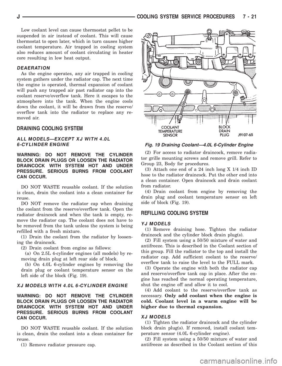
left side of the block (Fig. 19).
XJ MODELS WITH 4.0L 6-CYLINDER ENGINE
WARNING: DO NOT REMOVE THE CYLINDER
BLOCK DRAIN PLUGS OR LOOSEN THE RADIATOR
DRAINCOCK WITH SYSTEM HOT AND UNDER
PRESSURE. SERIOUS BURNS FROM COOLANT
CAN OCCUR.
DO NOT WASTE reusable coolant. If the solution
is clean, drain the coolant into a clean container for
reuse.
(1) Remove radiator pressure cap.(2) For access to radiator draincock, remove radia-
tor grille mounting screws and remove grill. Refer to
Group 23, Body for procedures.
(3) Attach one end of a 24 inch long X 1/4 inch ID
hose to the radiator draincock. Put the other end into
a clean container. Open draincock and drain coolant
from radiator.
(4) Drain coolant from engine by removing the
drain plug and coolant temperature sensor on left
side of block (Fig. 19).
REFILLING COOLING SYSTEM
YJ MODELS
(1) Remove draining hose. Tighten the radiator
draincock and the cylinder block drain plug(s).
(2) Fill system using a 50/50 mixture of water and
antifreeze. This is described in the Coolant section of
this group. Fill the radiator to the top and install the
radiator cap. Add sufficient coolant to the reserve/
overflow tank to raise the level to the FULL mark.
(3) Operate the engine with both the radiator cap
and reserve/overflow tank cap in place. After the en-
gine has reached the normal operating temperature,
shut the engine off and allow it to cool.
(4) Add coolant to the reserve/overflow tank as
necessary.Only add coolant when the engine is
cold. Coolant level in a warm engine will be
higher due to thermal expansion.
XJ MODELS
(1) Tighten the radiator draincock and the cylinder
block drain plug(s). If removed, install coolant tem-
perature sensor (4.0L 6-cylinder engine).
(2) Fill system using a 50/50 mixture of water and
antifreeze as described in the Coolant section of this
Fig. 19 Draining CoolantÐ4.0L 6-Cylinder Engine
JCOOLING SYSTEM SERVICE PROCEDURES 7 - 21
Page 266 of 2158
WARNING: CONSTANT TENSION HOSE CLAMPS
ARE USED ON MOST COOLING SYSTEM HOSES.
WHEN REMOVING OR INSTALLING, USE ONLY
TOOLS DESIGNED FOR SERVICING THIS TYPE OF
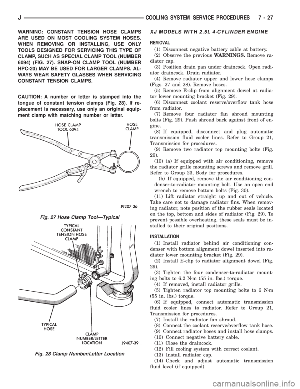
CLAMP, SUCH AS SPECIAL CLAMP TOOL (NUMBER
6094) (FIG. 27). SNAP-ON CLAMP TOOL (NUMBER
HPC-20) MAY BE USED FOR LARGER CLAMPS. AL-
WAYS WEAR SAFETY GLASSES WHEN SERVICING
CONSTANT TENSION CLAMPS.
CAUTION: A number or letter is stamped into the
tongue of constant tension clamps (Fig. 28). If re-
placement is necessary, use only an original equip-
ment clamp with matching number or letter.XJ MODELS WITH 2.5L 4-CYLINDER ENGINE
REMOVAL
(1) Disconnect negative battery cable at battery.
(2) Observe the previousWARNINGS.Remove ra-
diator cap.
(3) Position drain pan under draincock. Open radi-
ator draincock. Drain radiator.
(4) Remove radiator upper and lower hose clamps
(Figs. 27 and 28). Remove hoses.
(5) Remove E-clip from alignment dowel at radia-
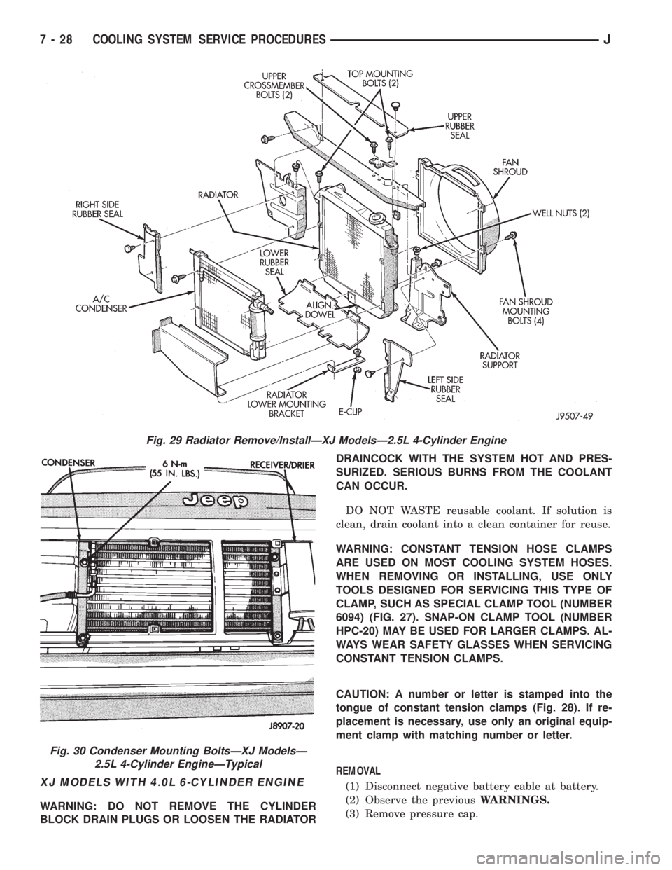
tor lower mounting bracket (Fig. 29).
(6) Disconnect coolant reserve/overflow tank hose
from radiator.
(7) Remove four radiator fan shroud mounting
bolts (Fig. 29). Push shroud back against front of en-
gine.
(8) If equipped, disconnect and plug automatic
transmission fluid cooler lines. Refer to Group 21,
Transmission for procedures.
(9) Remove two radiator top mounting bolts (Fig.
29).
(10) (a) If equipped with air conditioning, remove
the radiator grille mounting screws and remove grill.
Refer to Group 23, Body for procedures.
(b) If equipped, remove the air conditioning con-
denser-to-radiator mounting bolt. Use an open end
wrench to remove bottom bolts (Fig. 30).
(11) Lift radiator straight up and out of vehicle.
Take care not to damage radiator fins. When remov-
ing radiator, note position of the rubber seals located
on the top, bottom and sides of radiator (Fig. 29). To
prevent possible overheating, these seals must be in-
stalled to their original positions.
INSTALLATION
(1) Install radiator behind air conditioning con-
denser with bottom alignment dowel inserted into ra-
diator lower mounting bracket (Fig. 29).
(2) Install E-clip to radiator alignment dowel (Fig.
29).
(3) Tighten the four condenser-to-radiator mount-
ing bolts to 6.2 Nzm (55 in. lbs.) torque.
(4) If removed, install radiator grille.
(5) Tighten radiator top mounting bolts to 6 Nzm
(55 in. lbs.) torque.
(6) If equipped, connect automatic transmission
fluid cooler lines to radiator. Refer to Group 21,
Transmission for procedures.
(7) Install the radiator fan shroud.
(8) Connect the coolant reserve/overflow tank hose.
(9) Connect radiator hoses and install hose clamps.
(10) Connect negative battery cable.
(11) Close the draincock.
(12) Fill cooling system with correct coolant.
(13) Install radiator cap.
(14) Check and adjust automatic transmission
fluid level (if equipped).
Fig. 27 Hose Clamp ToolÐTypical
Fig. 28 Clamp Number/Letter Location
JCOOLING SYSTEM SERVICE PROCEDURES 7 - 27
Page 267 of 2158
XJ MODELS WITH 4.0L 6-CYLINDER ENGINE
WARNING: DO NOT REMOVE THE CYLINDER
BLOCK DRAIN PLUGS OR LOOSEN THE RADIATORDRAINCOCK WITH THE SYSTEM HOT AND PRES-
SURIZED. SERIOUS BURNS FROM THE COOLANT
CAN OCCUR.
DO NOT WASTE reusable coolant. If solution is
clean, drain coolant into a clean container for reuse.
WARNING: CONSTANT TENSION HOSE CLAMPS
ARE USED ON MOST COOLING SYSTEM HOSES.
WHEN REMOVING OR INSTALLING, USE ONLY
TOOLS DESIGNED FOR SERVICING THIS TYPE OF
CLAMP, SUCH AS SPECIAL CLAMP TOOL (NUMBER
6094) (FIG. 27). SNAP-ON CLAMP TOOL (NUMBER
HPC-20) MAY BE USED FOR LARGER CLAMPS. AL-
WAYS WEAR SAFETY GLASSES WHEN SERVICING
CONSTANT TENSION CLAMPS.
CAUTION: A number or letter is stamped into the
tongue of constant tension clamps (Fig. 28). If re-
placement is necessary, use only an original equip-
ment clamp with matching number or letter.
REMOVAL
(1) Disconnect negative battery cable at battery.
(2) Observe the previousWARNINGS.
(3) Remove pressure cap.
Fig. 29 Radiator Remove/InstallÐXJ ModelsÐ2.5L 4-Cylinder Engine
Fig. 30 Condenser Mounting BoltsÐXJ ModelsÐ
2.5L 4-Cylinder EngineÐTypical
7 - 28 COOLING SYSTEM SERVICE PROCEDURESJ
Page 276 of 2158
The auxiliary oil coolers on all models operate in
conjunction with the internal radiator mounted main
oil cooler. The transmission oil is routed through the
main cooler first, then the auxiliary cooler, before re-
turning to the transmission.REMOVAL/INSTALLATIONÐXJ MODELS
(1) Remove the grill mounting screws and remove
the grill. Refer to Group 23, Body for procedures.
(2) Place a drain pan below the transmission oil
cooler.
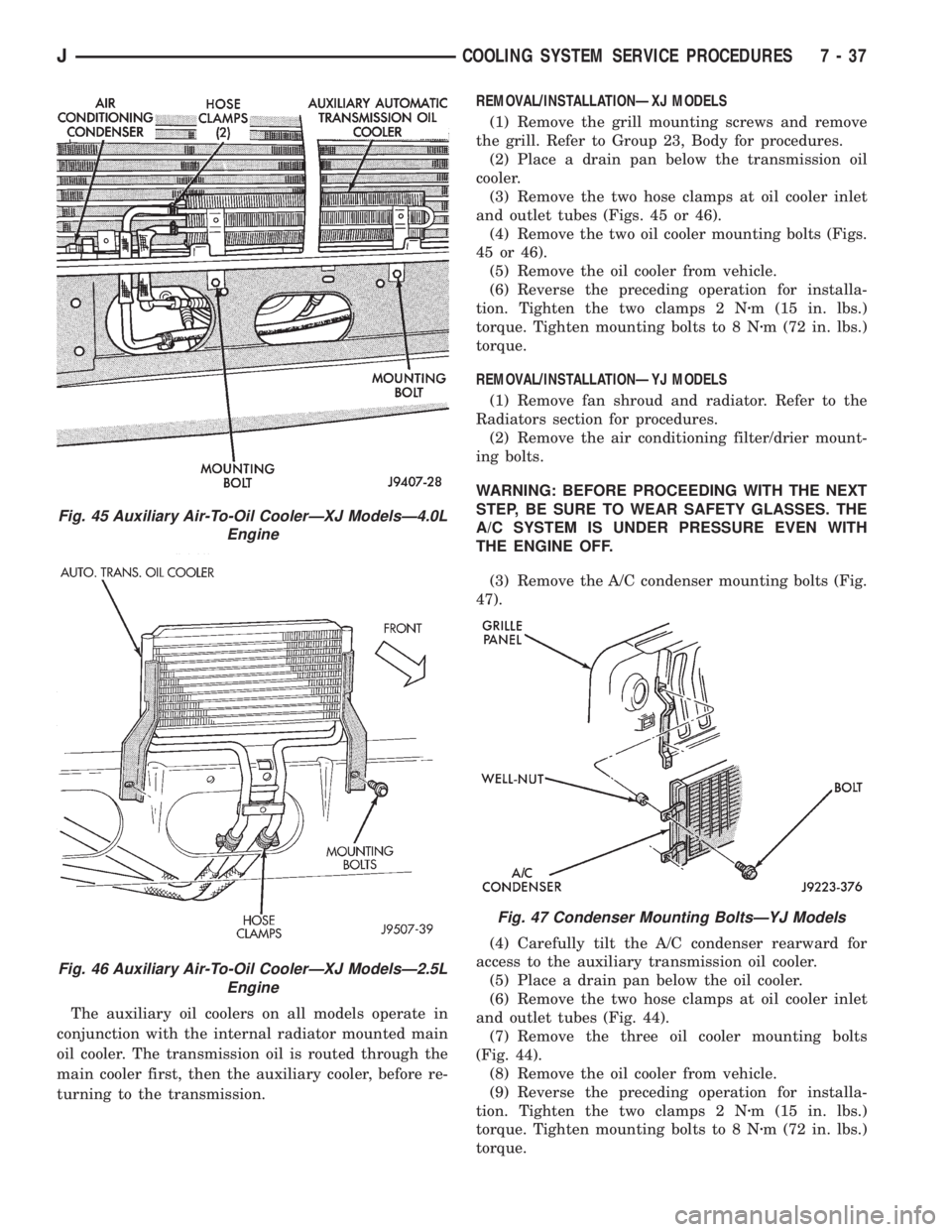
(3) Remove the two hose clamps at oil cooler inlet
and outlet tubes (Figs. 45 or 46).
(4) Remove the two oil cooler mounting bolts (Figs.
45 or 46).
(5) Remove the oil cooler from vehicle.
(6) Reverse the preceding operation for installa-
tion. Tighten the two clamps 2 Nzm (15 in. lbs.)
torque. Tighten mounting bolts to 8 Nzm (72 in. lbs.)
torque.
REMOVAL/INSTALLATIONÐYJ MODELS
(1) Remove fan shroud and radiator. Refer to the
Radiators section for procedures.
(2) Remove the air conditioning filter/drier mount-
ing bolts.
WARNING: BEFORE PROCEEDING WITH THE NEXT
STEP, BE SURE TO WEAR SAFETY GLASSES. THE
A/C SYSTEM IS UNDER PRESSURE EVEN WITH
THE ENGINE OFF.
(3) Remove the A/C condenser mounting bolts (Fig.
47).
(4) Carefully tilt the A/C condenser rearward for
access to the auxiliary transmission oil cooler.
(5) Place a drain pan below the oil cooler.
(6) Remove the two hose clamps at oil cooler inlet
and outlet tubes (Fig. 44).
(7) Remove the three oil cooler mounting bolts
(Fig. 44).
(8) Remove the oil cooler from vehicle.
(9) Reverse the preceding operation for installa-
tion. Tighten the two clamps 2 Nzm (15 in. lbs.)
torque. Tighten mounting bolts to 8 Nzm (72 in. lbs.)
torque.
Fig. 45 Auxiliary Air-To-Oil CoolerÐXJ ModelsÐ4.0L
Engine
Fig. 46 Auxiliary Air-To-Oil CoolerÐXJ ModelsÐ2.5L
Engine
Fig. 47 Condenser Mounting BoltsÐYJ Models
JCOOLING SYSTEM SERVICE PROCEDURES 7 - 37
Page 279 of 2158
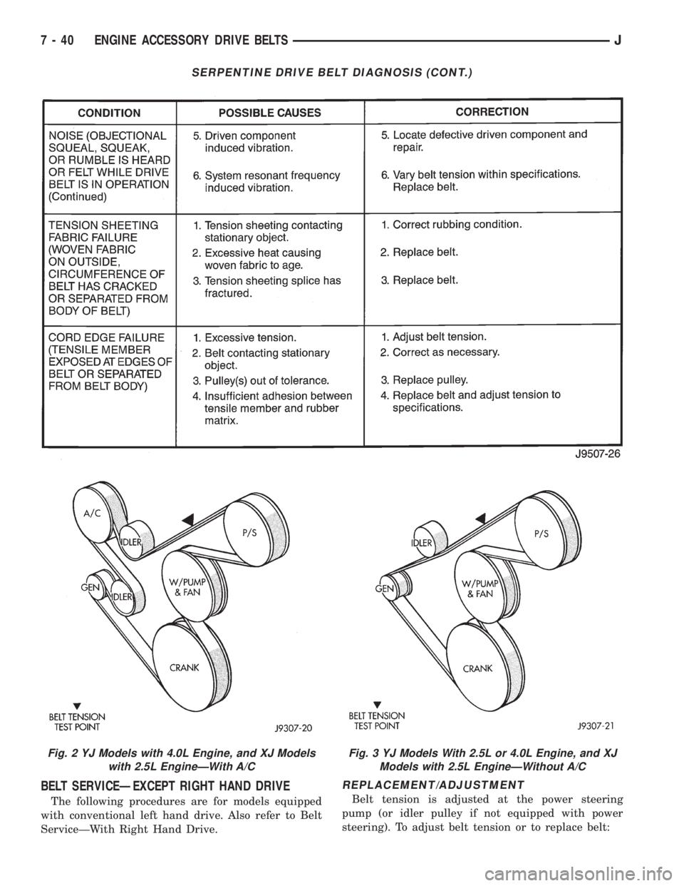
BELT SERVICEÐEXCEPT RIGHT HAND DRIVE
The following procedures are for models equipped
with conventional left hand drive. Also refer to Belt
ServiceÐWith Right Hand Drive.
REPLACEMENT/ADJUSTMENT
Belt tension is adjusted at the power steering
pump (or idler pulley if not equipped with power
steering). To adjust belt tension or to replace belt:
SERPENTINE DRIVE BELT DIAGNOSIS (CONT.)
Fig. 2 YJ Models with 4.0L Engine, and XJ Models
with 2.5L EngineÐWith A/CFig. 3 YJ Models With 2.5L or 4.0L Engine, and XJ
Models with 2.5L EngineÐWithout A/C
7 - 40 ENGINE ACCESSORY DRIVE BELTSJ
Page 283 of 2158
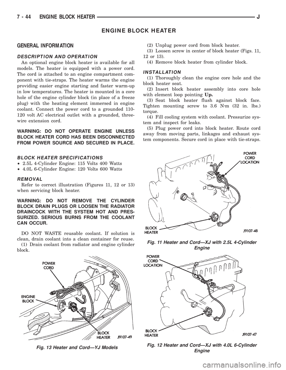
ENGINE BLOCK HEATER
GENERAL INFORMATION
DESCRIPTION AND OPERATION
An optional engine block heater is available for all
models. The heater is equipped with a power cord.
The cord is attached to an engine compartment com-
ponent with tie-straps. The heater warms the engine
providing easier engine starting and faster warm-up
in low temperatures. The heater is mounted in a core
hole of the engine cylinder block (in place of a freeze
plug) with the heating element immersed in engine
coolant. Connect the power cord to a grounded 110-
120 volt AC electrical outlet with a grounded, three-
wire extension cord.
WARNING: DO NOT OPERATE ENGINE UNLESS
BLOCK HEATER CORD HAS BEEN DISCONNECTED
FROM POWER SOURCE AND SECURED IN PLACE.
BLOCK HEATER SPECIFICATIONS
²2.5L 4-Cylinder Engine: 115 Volts 400 Watts
²4.0L 6-Cylinder Engine: 120 Volts 600 Watts
REMOVAL
Refer to correct illustration (Figures 11, 12 or 13)
when servicing block heater.
WARNING: DO NOT REMOVE THE CYLINDER
BLOCK DRAIN PLUGS OR LOOSEN THE RADIATOR
DRAINCOCK WITH THE SYSTEM HOT AND PRES-
SURIZED. SERIOUS BURNS FROM THE COOLANT
CAN OCCUR.
DO NOT WASTE reusable coolant. If solution is
clean, drain coolant into a clean container for reuse.
(1) Drain coolant from radiator and engine cylinder
block.(2) Unplug power cord from block heater.
(3) Loosen screw in center of block heater (Figs. 11,
12 or 13).
(4) Remove block heater from cylinder block.
INSTALLATION
(1) Thoroughly clean the engine core hole and the
block heater seat.
(2) Insert block heater assembly into core hole
with element loop pointingUp.
(3) Seat block heater flush against block face.
Tighten mounting screw to 3.6 Nzm (32 in. lbs.)
torque.
(4) Fill cooling system with coolant. Pressurize sys-
tem and inspect for leaks.
(5) Plug power cord into block heater. Route cord
away from moving parts, linkages and exhaust sys-
tem components. Secure cord in place with tie-straps.
Fig. 13 Heater and CordÐYJ Models
Fig. 11 Heater and CordÐXJ with 2.5L 4-Cylinder
Engine
Fig. 12 Heater and CordÐXJ with 4.0L 6-Cylinder
Engine
7 - 44 ENGINE BLOCK HEATERJ
Page 298 of 2158
COLD CRANKING TEST
(1) Battery must be fully-charged and load tested
before proceeding. See Battery, in this group.
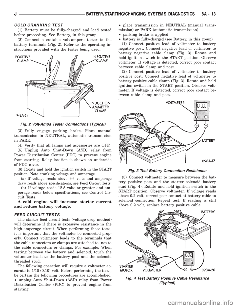
(2) Connect a suitable volt-ampere tester to the
battery terminals (Fig. 2). Refer to the operating in-
structions provided with the tester being used.
(3) Fully engage parking brake. Place manual
transmission in NEUTRAL, automatic transmission
in PARK.
(4) Verify that all lamps and accessories are OFF.
(5) Unplug Auto Shut-Down (ASD) relay from
Power Distribution Center (PDC) to prevent engine
from starting. Relay location is shown on underside
of PDC cover.
(6) Rotate and hold the ignition switch in the START
position. Note cranking voltage and amperage.
(a) If voltage reads above 9.6 volts and amperage
draw reads above specifications, see Feed Circuit Tests.
(b) If voltage reads 12.5 volts or greater and am-
perage reads below specifications, see Control Cir-
cuit Tests.
A cold engine will increase starter current
and reduce battery voltage.
FEED CIRCUIT TESTS
The starter feed circuit tests (voltage drop method)
will determine if there is excessive resistance in the
high-amperage circuit. When performing these tests,
it is important that the voltmeter be connected prop-
erly. Connect voltmeter leads to the terminals that
the cable connectors or clamps are attached to, not to
the cable connectors or clamps. For example: When
testing between the battery and solenoid, touch the
voltmeter leads to the battery post and the solenoid
threaded stud.
The following operation will require a voltmeter ac-
curate to 1/10 (0.10) volt. Before performing the tests,
be certain the following procedures are accomplished:
²unplug Auto Shut-Down (ASD) relay from Power
Distribution Center (PDC) to prevent engine from
starting²place transmission in NEUTRAL (manual trans-
mission) or PARK (automatic transmission)
²parking brake is applied
²
battery is fully-charged (see Battery, in this group).
(1) Connect positive lead of voltmeter to battery
negative post. Connect negative lead of voltmeter to
battery negative cable clamp (Fig. 3). Rotate and
hold ignition switch in the START position. Observe
voltmeter. If voltage is detected, correct poor contact
between cable clamp and post.
(2) Connect positive lead of voltmeter to battery
positive post. Connect negative lead of voltmeter to
battery positive cable clamp (Fig. 3). Rotate and hold
ignition switch in the START position. Observe volt-
meter. If voltage is detected, correct poor contact be-
tween cable clamp and post.
(3) Connect voltmeter to measure between the bat-
tery positive post and the starter solenoid battery
stud (Fig. 4). Rotate and hold ignition switch in the
START position. Observe voltmeter. If voltage reads
above 0.2 volt, correct poor contact at battery cable to
solenoid connection. Repeat test. If reading is still
above 0.2 volt, replace battery positive cable.
Fig. 2 Volt-Amps Tester Connections (Typical)
Fig. 3 Test Battery Connection Resistance
Fig. 4 Test Battery Positive Cable Resistance
(Typical)
JBATTERY/STARTING/CHARGING SYSTEMS DIAGNOSTICS 8A - 13
Page 301 of 2158
IGNITION SWITCH TEST
Refer to Group 8D - Ignition Systems for testing
and service of this component.
PARK/NEUTRAL POSITION SWITCH TEST
Refer to Group 21 - Transmission and Transfer
Case for testing and service of this component.
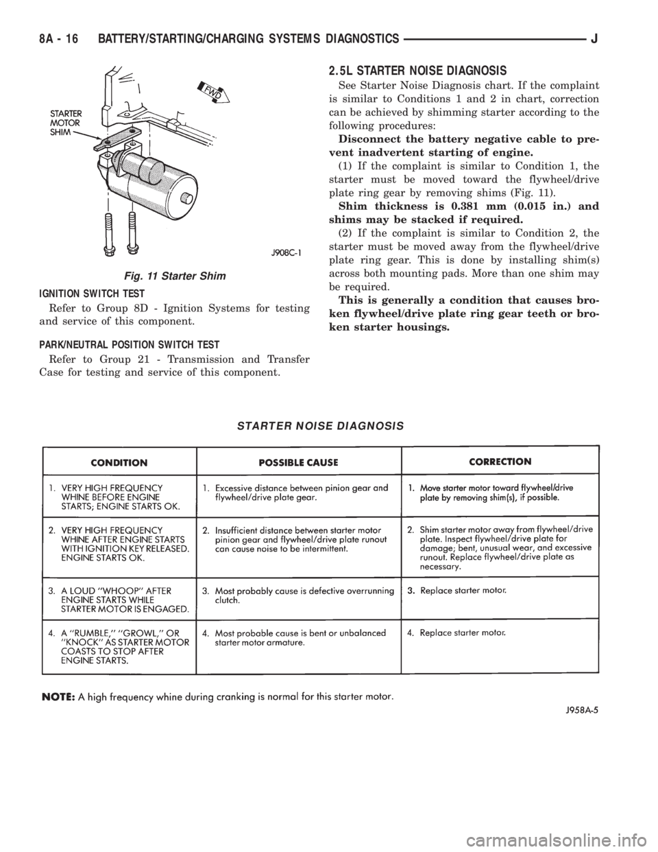
2.5L STARTER NOISE DIAGNOSIS
See Starter Noise Diagnosis chart. If the complaint
is similar to Conditions 1 and 2 in chart, correction
can be achieved by shimming starter according to the
following procedures:
Disconnect the battery negative cable to pre-
vent inadvertent starting of engine.
(1) If the complaint is similar to Condition 1, the
starter must be moved toward the flywheel/drive
plate ring gear by removing shims (Fig. 11).
Shim thickness is 0.381 mm (0.015 in.) and
shims may be stacked if required.
(2) If the complaint is similar to Condition 2, the
starter must be moved away from the flywheel/drive
plate ring gear. This is done by installing shim(s)
across both mounting pads. More than one shim may
be required.
This is generally a condition that causes bro-
ken flywheel/drive plate ring gear teeth or bro-
ken starter housings.
STARTER NOISE DIAGNOSIS
Fig. 11 Starter Shim
8A - 16 BATTERY/STARTING/CHARGING SYSTEMS DIAGNOSTICSJ
Page 312 of 2158
CAUTION: Be certain that battery cables are con-
nected to the correct battery terminals. Reverse po-
larity can damage electrical components.
(12) Place oiled felt washer on battery positive ter-
minal post.
(13) Install and tighten battery positive cable ter-
minal clamp. Then install and tighten negative cableterminal clamp. Both cable clamp bolts require
torque of 8.5 Nzm (75 in. lbs.).
(14) Apply a thin coating of petroleum jelly or
chassis grease to cable terminals and battery posts.
STARTER AND STARTER RELAY
GENERAL INFORMATION
This section covers starter and starter relay service
procedures only. For diagnostic procedures, refer to
Group 8A - Battery/Starting/Charging Systems Diag-
nostics. Service procedures for other starting system
components can be found as follows:
²battery - see Battery, in this group
²ignition switch - refer to Group 8D - Ignition Sys-
tems
²park/neutral position switch (automatic transmis-
sion) - refer to Group 21 - Transmission and Transfer
Case
²wiring harness and connectors - refer to Group 8W
- Wiring Diagrams.
STARTER
The starter motor incorporates several features to
create a reliable, efficient, compact and lightweight
unit. A planetary gear system (intermediate trans-
mission) is used between the electric motor and pin-
ion gear. This feature makes it possible to reduce the
dimensions of the starter. At the same time, it allows
higher armature rotational speed and delivers in-
creased torque through the pinion gear to the fly-
wheel or drive plate ring gear.
The use of a permanent magnet field also reduces
starter size and weight. This field consists of six
high-strength permanent magnets. The magnets are
aligned according to their polarity and are perma-
nently fixed in the starter field frame.
The starter motors for all engines are activated by
a solenoid mounted to the overrunning clutch hous-
ing. However, the starter motor/solenoid are serviced
only as a complete assembly. If either component
fails, the entire assembly must be replaced.
This unit is highly sensitive to hammering, shocks
and external pressure.
CAUTION: The starter motor MUST NOT BE
CLAMPED in a vise by the starter field frame. Doing
so may damage the magnets. It may be clamped by
the mounting flange ONLY.CAUTION: Do not connect starter motor incorrectly
when tests are being performed. The permanent
magnets may be damaged and rendered unservice-
able.
STARTER RELAY
The starter relay is an International Standards Or-
ganization (ISO) type relay, and is located in the
Power Distribution Center (PDC). Refer to underside
of PDC cover for relay location.
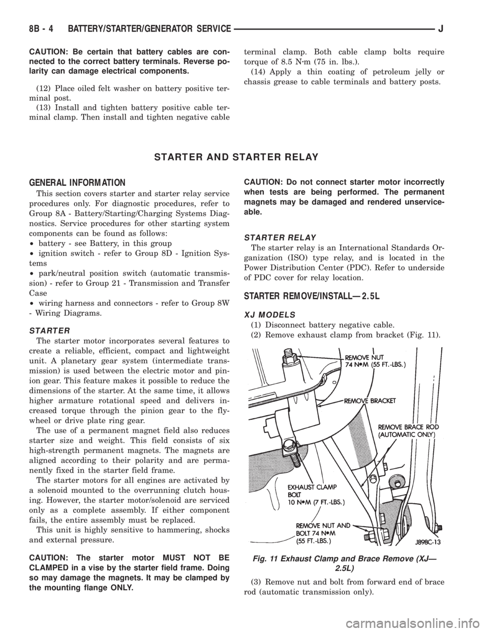
STARTER REMOVE/INSTALLÐ2.5L
XJ MODELS
(1) Disconnect battery negative cable.
(2) Remove exhaust clamp from bracket (Fig. 11).
(3) Remove nut and bolt from forward end of brace
rod (automatic transmission only).
Fig. 11 Exhaust Clamp and Brace Remove (XJÐ
2.5L)
8B - 4 BATTERY/STARTER/GENERATOR SERVICEJ
Page 314 of 2158
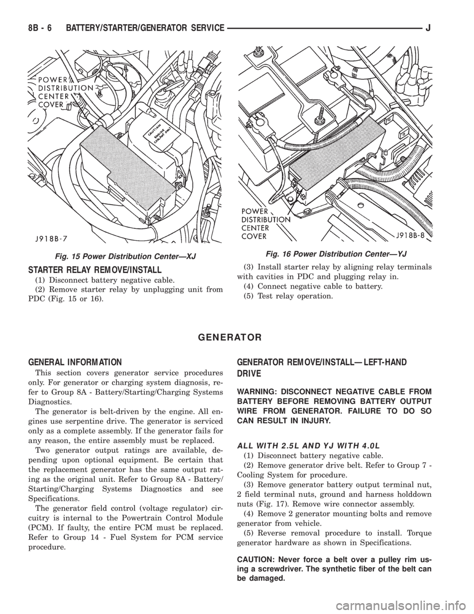
STARTER RELAY REMOVE/INSTALL
(1) Disconnect battery negative cable.
(2) Remove starter relay by unplugging unit from
PDC (Fig. 15 or 16).(3) Install starter relay by aligning relay terminals
with cavities in PDC and plugging relay in.
(4) Connect negative cable to battery.
(5) Test relay operation.
GENERATOR
GENERAL INFORMATION
This section covers generator service procedures
only. For generator or charging system diagnosis, re-
fer to Group 8A - Battery/Starting/Charging Systems
Diagnostics.
The generator is belt-driven by the engine. All en-
gines use serpentine drive. The generator is serviced
only as a complete assembly. If the generator fails for
any reason, the entire assembly must be replaced.
Two generator output ratings are available, de-
pending upon optional equipment. Be certain that
the replacement generator has the same output rat-
ing as the original unit. Refer to Group 8A - Battery/
Starting/Charging Systems Diagnostics and see
Specifications.
The generator field control (voltage regulator) cir-
cuitry is internal to the Powertrain Control Module
(PCM). If faulty, the entire PCM must be replaced.
Refer to Group 14 - Fuel System for PCM service
procedure.
GENERATOR REMOVE/INSTALLÐLEFT-HAND
DRIVE
WARNING: DISCONNECT NEGATIVE CABLE FROM
BATTERY BEFORE REMOVING BATTERY OUTPUT
WIRE FROM GENERATOR. FAILURE TO DO SO
CAN RESULT IN INJURY.
ALL WITH 2.5L AND YJ WITH 4.0L
(1) Disconnect battery negative cable.
(2) Remove generator drive belt. Refer to Group 7 -
Cooling System for procedure.
(3) Remove generator battery output terminal nut,
2 field terminal nuts, ground and harness holddown
nuts (Fig. 17). Remove wire connector assembly.
(4) Remove 2 generator mounting bolts and remove
generator from vehicle.
(5) Reverse removal procedure to install. Torque
generator hardware as shown in Specifications.
CAUTION: Never force a belt over a pulley rim us-
ing a screwdriver. The synthetic fiber of the belt can
be damaged.
Fig. 15 Power Distribution CenterÐXJFig. 16 Power Distribution CenterÐYJ
8B - 6 BATTERY/STARTER/GENERATOR SERVICEJ