2.5 engine JEEP YJ 1995 Service And Service Manual
[x] Cancel search | Manufacturer: JEEP, Model Year: 1995, Model line: YJ, Model: JEEP YJ 1995Pages: 2158, PDF Size: 81.9 MB
Page 594 of 2158
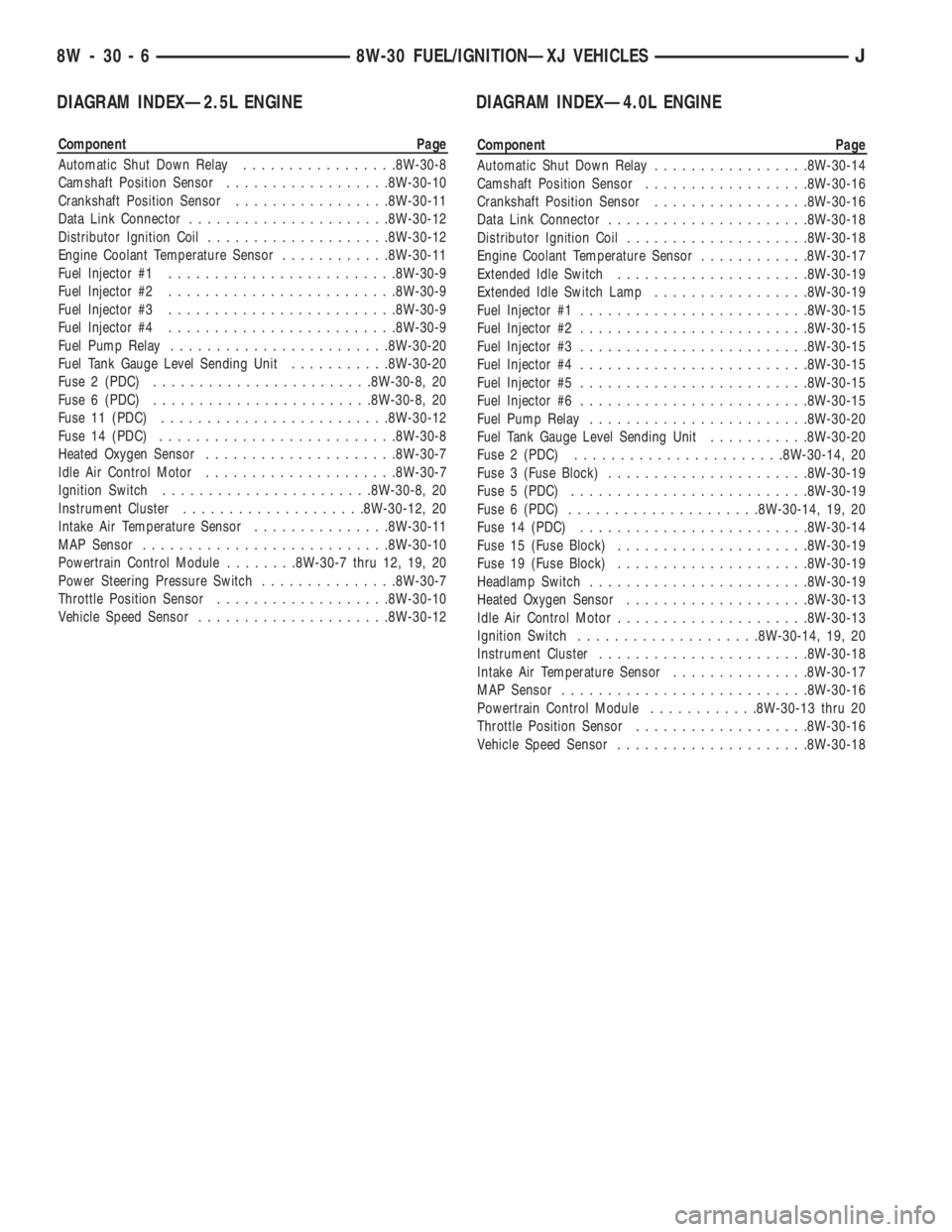
DIAGRAM INDEXÐ2.5L ENGINE
Component Page
Automatic Shut Down Relay.................8W-30-8
Camshaft Position Sensor..................8W-30-10
Crankshaft Position Sensor.................8W-30-11
Data Link Connector......................8W-30-12
Distributor Ignition Coil....................8W-30-12
Engine Coolant Temperature Sensor............8W-30-11
Fuel Injector #1.........................8W-30-9
Fuel Injector #2.........................8W-30-9
Fuel Injector #3.........................8W-30-9
Fuel Injector #4.........................8W-30-9
Fuel Pump Relay........................8W-30-20
Fuel Tank Gauge Level Sending Unit...........8W-30-20
Fuse 2 (PDC)........................8W-30-8, 20
Fuse 6 (PDC)........................8W-30-8, 20
Fuse 11 (PDC).........................8W-30-12
Fuse 14 (PDC)..........................8W-30-8
Heated Oxygen Sensor.....................8W-30-7
Idle Air Control Motor.....................8W-30-7
Ignition Switch.......................8W-30-8, 20
Instrument Cluster....................8W-30-12, 20
Intake Air Temperature Sensor...............8W-30-11
MAP Sensor...........................8W-30-10
Powertrain Control Module........8W-30-7 thru 12, 19, 20
Power Steering Pressure Switch...............8W-30-7
Throttle Position Sensor...................8W-30-10
Vehicle Speed Sensor.....................8W-30-12
DIAGRAM INDEXÐ4.0L ENGINE
Component Page
Automatic Shut Down Relay.................8W-30-14
Camshaft Position Sensor..................8W-30-16
Crankshaft Position Sensor.................8W-30-16
Data Link Connector......................8W-30-18
Distributor Ignition Coil....................8W-30-18
Engine Coolant Temperature Sensor............8W-30-17
Extended Idle Switch.....................8W-30-19
Extended Idle Switch Lamp.................8W-30-19
Fuel Injector #1.........................8W-30-15
Fuel Injector #2.........................8W-30-15
Fuel Injector #3.........................8W-30-15
Fuel Injector #4.........................8W-30-15
Fuel Injector #5.........................8W-30-15
Fuel Injector #6.........................8W-30-15
Fuel Pump Relay........................8W-30-20
Fuel Tank Gauge Level Sending Unit...........8W-30-20
Fuse 2 (PDC).......................8W-30-14, 20
Fuse 3 (Fuse Block)......................8W-30-19
Fuse 5 (PDC)..........................8W-30-19
Fuse 6 (PDC).....................8W-30-14, 19, 20
Fuse 14 (PDC).........................8W-30-14
Fuse 15 (Fuse Block).....................8W-30-19
Fuse 19 (Fuse Block).....................8W-30-19
Headlamp Switch........................8W-30-19
Heated Oxygen Sensor....................8W-30-13
Idle Air Control Motor.....................8W-30-13
Ignition Switch....................8W-30-14, 19, 20
Instrument Cluster.......................8W-30-18
Intake Air Temperature Sensor...............8W-30-17
MAP Sensor...........................8W-30-16
Powertrain Control Module............8W-30-13 thru 20
Throttle Position Sensor...................8W-30-16
Vehicle Speed Sensor.....................8W-30-18
8W - 30 - 6 8W-30 FUEL/IGNITIONÐXJ VEHICLESJ
Page 609 of 2158
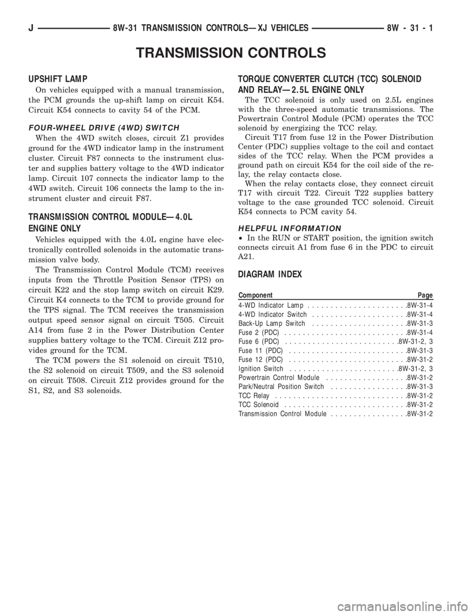
TRANSMISSION CONTROLS
UPSHIFT LAMP
On vehicles equipped with a manual transmission,
the PCM grounds the up-shift lamp on circuit K54.
Circuit K54 connects to cavity 54 of the PCM.
FOUR-WHEEL DRIVE (4WD) SWITCH
When the 4WD switch closes, circuit Z1 provides
ground for the 4WD indicator lamp in the instrument
cluster. Circuit F87 connects to the instrument clus-
ter and supplies battery voltage to the 4WD indicator
lamp. Circuit 107 connects the indicator lamp to the
4WD switch. Circuit 106 connects the lamp to the in-
strument cluster and circuit F87.
TRANSMISSION CONTROL MODULEÐ4.0L
ENGINE ONLY
Vehicles equipped with the 4.0L engine have elec-
tronically controlled solenoids in the automatic trans-
mission valve body.
The Transmission Control Module (TCM) receives
inputs from the Throttle Position Sensor (TPS) on
circuit K22 and the stop lamp switch on circuit K29.
Circuit K4 connects to the TCM to provide ground for
the TPS signal. The TCM receives the transmission
output speed sensor signal on circuit T505. Circuit
A14 from fuse 2 in the Power Distribution Center
supplies battery voltage to the TCM. Circuit Z12 pro-
vides ground for the TCM.
The TCM powers the S1 solenoid on circuit T510,
the S2 solenoid on circuit T509, and the S3 solenoid
on circuit T508. Circuit Z12 provides ground for the
S1, S2, and S3 solenoids.
TORQUE CONVERTER CLUTCH (TCC) SOLENOID
AND RELAYÐ2.5L ENGINE ONLY
The TCC solenoid is only used on 2.5L engines
with the three-speed automatic transmissions. The
Powertrain Control Module (PCM) operates the TCC
solenoid by energizing the TCC relay.
Circuit T17 from fuse 12 in the Power Distribution
Center (PDC) supplies voltage to the coil and contact
sides of the TCC relay. When the PCM provides a
ground path on circuit K54 for the coil side of the re-
lay, the relay contacts close.
When the relay contacts close, they connect circuit
T17 with circuit T22. Circuit T22 supplies battery
voltage to the case grounded TCC solenoid. Circuit
K54 connects to PCM cavity 54.
HELPFUL INFORMATION
²In the RUN or START position, the ignition switch
connects circuit A1 from fuse 6 in the PDC to circuit
A21.
DIAGRAM INDEX
Component Page
4-WD Indicator Lamp......................8W-31-4
4-WD Indicator Switch.....................8W-31-4
Back-Up Lamp Switch.....................8W-31-3
Fuse 2 (PDC)...........................8W-31-4
Fuse 6 (PDC).........................8W-31-2, 3
Fuse 11 (PDC)..........................8W-31-3
Fuse 12 (PDC)..........................8W-31-2
Ignition Switch........................8W-31-2, 3
Powertrain Control Module..................8W-31-2
Park/Neutral Position Switch.................8W-31-3
TCC Relay.............................8W-31-2
TCC Solenoid...........................8W-31-2
Transmission Control Module.................8W-31-2
J8W-31 TRANSMISSION CONTROLSÐXJ VEHICLES 8W - 31 - 1
Page 788 of 2158
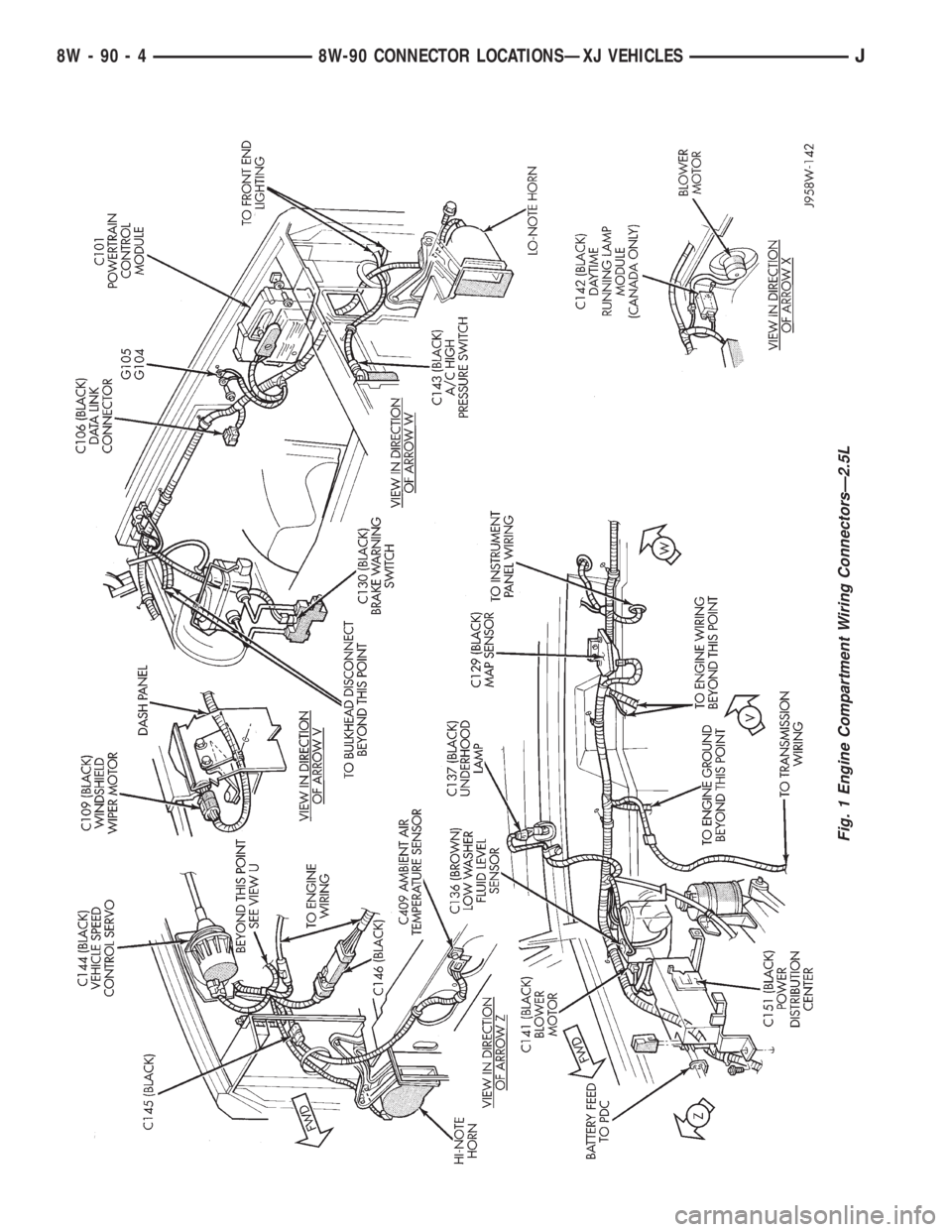
Fig. 1 Engine Compartment Wiring ConnectorsÐ2.5L
8W - 90 - 4 8W-90 CONNECTOR LOCATIONSÐXJ VEHICLESJ
Page 793 of 2158
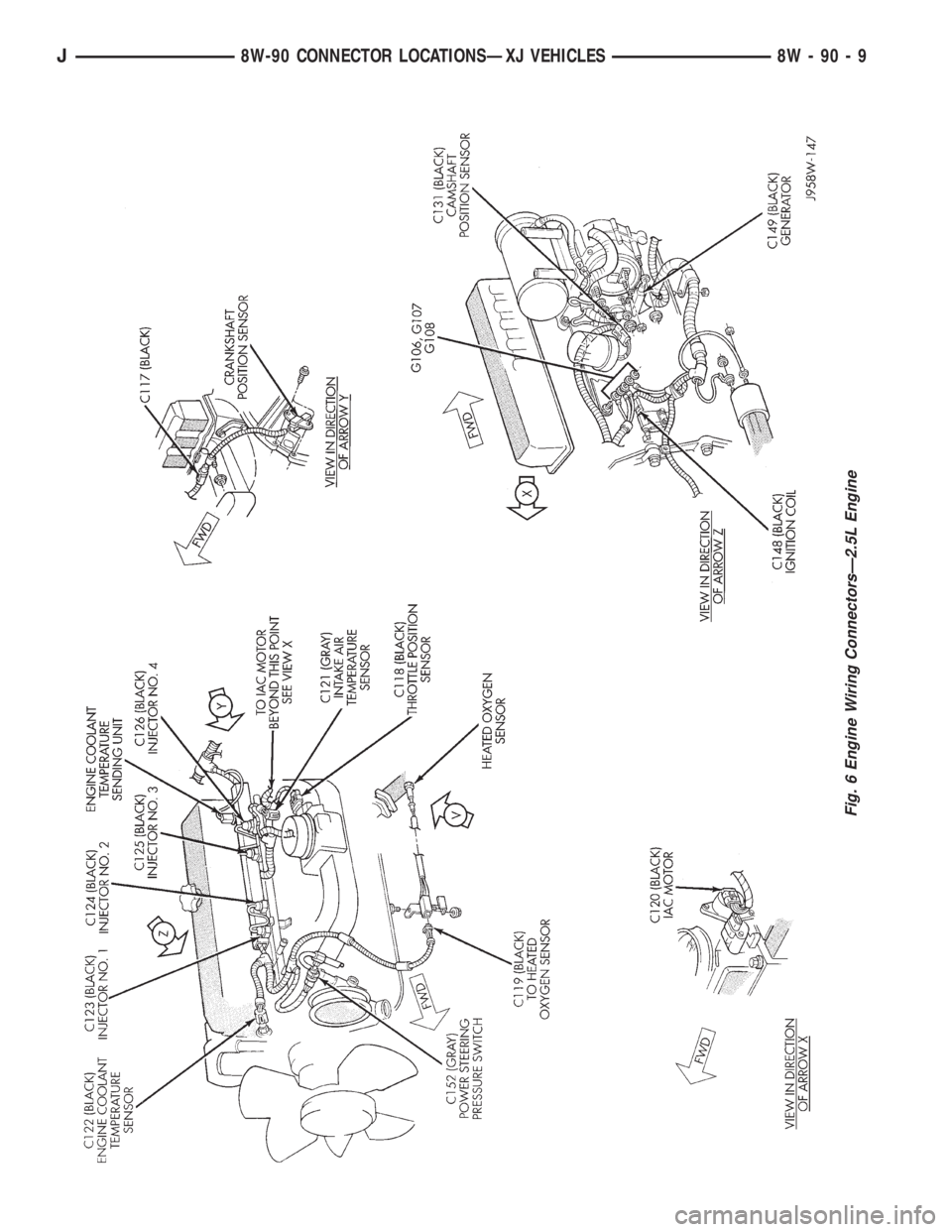
Fig. 6 Engine Wiring ConnectorsÐ2.5L Engine
J8W-90 CONNECTOR LOCATIONSÐXJ VEHICLES 8W - 90 - 9
Page 813 of 2158
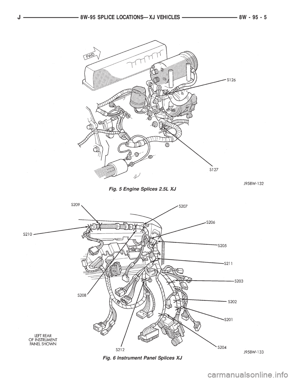
Fig. 5 Engine Splices 2.5L XJ
Fig. 6 Instrument Panel Splices XJ
J8W-95 SPLICE LOCATIONSÐXJ VEHICLES 8W - 95 - 5
Page 1126 of 2158
switch to ground on circuit Z1. The switch closes dur-
ing periods of high power steering pump load and
low engine speed; such as parking maneuvers. Cir-
cuit K10 connects to cavity 10 of the PCM.
TACHOMETER SIGNAL
The Powertrain Control Module (PCM) supplies the
signal for the tachometer on circuit G21. Circuit G21
connects to cavity 43 of the PCM.
MALFUNCTION INDICATOR LAMP (MIL)
The Powertrain Control Module (PCM) provides
ground for the instrument cluster malfunction indica-
tor lamp on circuit G3. The MIL displays the mes-
sage CHECK ENGINE when illuminated. Circuit G5
provides voltage for the lamp.
DATA LINK CONNECTOR
Circuit G50 supplies battery voltage to the data
link connector. Circuit G50 originates at fuse 5 in the
fuse block. Circuit G50 is double crimped at the data
link connector and connects to cavity 9 of the Power-
train Control Module (PCM).
Circuit A21 from the ignition switch powers fuse 5
when the switch is in the START or RUN positions.
In the START or RUN position the ignition switch
connects circuit A1 from fuse 4 in the Power Distri-
bution Center (PDC) with circuit A21.
Circuit D20 connects to cavity 45 of the PCM. Cir-
cuit D20 is the SCI receive circuit for the PCM.
Circuit D21 connects to cavity 25 of the PCM. Cir-
cuit D21 is the SCI transmit circuit for the PCM.
Circuit Z11 provides ground for the data link con-
nector. Circuit Z11 splices to circuit Z1 which termi-
nates at the right rear of the engine. Circuit Z11 also
connects to cavity 5 of the PCM.
HELPFUL INFORMATION
²Circuit Z1 also supplies a ground for the PCM
high current drivers.
²If the system loses ground for the Z1 and Z11 cir-
cuits at the right rear of the engine, the vehicle will
not operate. Check the connection at the ganged-
ground circuit eyelet.
BRAKE SWITCH INPUT
Circuit V40 provides the brake switch input to the
Powertrain Control Module (PCM). Circuit V40 con-
nects to cavity 29 of the PCM.
POWER (DEVICE) GROUND
Circuit Z11 connects to cavities 11 and 12 of the
Powertrain Control Module (PCM). The Z1 circuit
provides ground for PCM internal drivers that oper-
ate high current devices like the injectors and igni-
tion coil.
Internal to the PCM, the power (device) ground cir-
cuit connects to the PCM sensor return circuit (from
circuit K4).
HELPFUL INFORMATION
²The grounding point for circuit Z1 is the right rear
of the engine.
²If the system loses ground for the Z1 circuits at
the rear of the engine, the vehicle will not operate.
Check the connection at the ganged-ground circuit
eyelet.
DIAGRAM INDEX
Component Page
Automatic Shut Down Relay...............8W-30-6, 14
Camshaft Position Sensor................8W-30-10, 16
Crankshaft Position Sensor...............8W-30-10, 16
Data Link Connector...................8W-30-11, 17
Daytime Running Lamps (DRL) Module.......8W-30-11, 17
Engine Coolant Temperature Sensor..........8W-30-9, 18
Fuel Pump Relay........................8W-30-20
Fuel Tank Level Unit......................8W-30-21
Fuse 1 (PDC)........................8W-30-6, 14
Fuse 4 (PDC)........................8W-30-6, 14
Fuse 5 (Fuse Block).................8W-30-6, 14, 20
Heated Oxygen Sensor..................8W-30-7, 15
Idle Air Control Motor..................8W-30-12, 18
Ignition Switch.....................8W-30-6, 14, 20
Ignition Coil........................8W-30-12, 18
Injectors (4.0L).........................8W-30-13
Injectors (2.5L)..........................8W-30-8
Instrument Cluster....................8W-30-11, 17
Intake Air Temperature Sensor.............8W-30-9, 18
MAP Sensor.........................8W-30-9, 18
Power Steering Pressure Switch..............8W-30-12
Powertrain Control Module.............8W-30-6 thru 21
Throttle Position Sensor.................8W-30-9, 18
Vehicle Speed Sensor..................8W-30-11, 17
J8W-30 FUEL/IGNITIONÐYJ VEHICLES 8W - 30 - 5
Page 1169 of 2158
AIR CONDITIONING AND HEATER
GENERAL INFORMATION
On vehicles built with the 2.5L engine, the electri-
cal system has provisions for dealer installed air con-
ditioning. The provisions consist of two connectors
which include circuitry for:
²Circuit C1 - Ignition feed
²Circuit C21 - Blower motor switch
²Circuit C91 - A/C request signal
²Circuit C20 - A/C select signal
²Circuit C13 - Ground for coil side of A/C compres-
sor clutch relay
²Circuit G5 - Battery voltage for coil side of A/C
compressor clutch relay
A/C COMPRESSOR
When the ignition switch is in the RUN position it
connects circuit A1 from fuse 4 in the Power Distri-
bution Center (PDC) to circuit A22. Circuit A22 sup-
plies battery voltage to fuse 12 in the fuse block.
Fuse 12 powers circuit C1.
Circuit C1 supplies battery voltage to the A/C
blower switch. Circuit C21 connects the A/C blower
switch to the A/C low pressure switch.
When the operator selects A/C operation, the A/C
blower switch provides the A/C request signal to cav-
ity 27 of the Powertrain Control Module (PCM) on
circuit C91. At the same time, the blower switch sup-
plies voltage through the A/C thermostat to circuit
C21.
Circuit C21 supplies voltage to the A/C low pres-
sure switch. When the A/C low pressure switch
closes, circuit C20 provides battery voltage to the
contact side of the A/C compressor clutch relay and
provides the A/C select signal to the PCM. Circuit
C20 is double crimped at the contact side of the re-
lay. The C20 circuit branch from the relay supplies
the A/C select input to cavity 28 of the PCM.
After receiving the A/C request signal, the PCM en-
ergizes the A/C compressor clutch relay by providing
ground for the coil side of the relay on circuit C13.
Circuit C13 connects to cavity 34 of the PCM.
Circuit G5 from fuse 9 in the fuse block supplies
voltage to the coil side of the relay. In the START or
RUN positions the ignition switch connects circuit A1
from fuse 4 in the PDC with circuit A21. Circuit A21
connects to the fuse block bus bar that powers circuit
C5 through fuse 9.
When the PCM energizes the A/C compressor
clutch relay, the relay switches from its normally
grounded position to connect circuit C20 to circuit
C3. Circuit C3 supplies voltage to the case grounded
A/C compressor clutch.
HELPFUL INFORMATION
²Circuit G5 is double crimped at the coil side of the
A/C compressor clutch relay. The G5 branch from the
relay continues to the back-up lamp switch.
²Circuit Z1 provides ground for the A/C compressor
clutch relay when the relay is in its normally
grounded position.
A/C-HEATER BLOWER MOTOR
When the ignition switch is in the RUN position it
connects circuit A1 from fuse 4 in the Power Distri-
bution Center (PDC) to circuit A22. Circuit A22 sup-
plies battery voltage to fuse 12 in the fuse block.
Fuse 12 powers circuit C1.
Circuit C1 supplies battery voltage to the A/C
blower switch. In the LOW position, the A/C blower
switch supplies voltage to the low speed brush of the
blower motor. In the MEDIUM position, the switch
supplies voltage to the medium speed bush of the
blower motor. In the HIGH position, the switch sup-
plies voltage to the high speed brush of the blower
motor.
The blower motor has a field jumper. The ground
circuit for the blower motor connects to the cigar
lighter. Circuit Z1 provides ground for the blower mo-
tor and the cigar lighter.
HELPFUL INFORMATION
²Check fuse 4 in the PDC.
²Check fuse 12 in the fuse block.
DIAGRAM INDEX
Component Page
A/C Compressor Clutch.....................8W-42-4
A/C Compressor Clutch Relay................8W-42-4
A/C Thermostat..........................8W-42-5
Blower Motor...........................8W-42-5
Blower Motor Switch......................8W-42-5
Fuse 4 (PDC).........................8W-42-4, 6
Fuse 7 (Fuse Block).......................8W-42-6
Fuse 9 (Fuse Block).....................8W-42-4, 6
Fuse 12 (Fuse Block)....................8W-42-4, 6
Ignition Switch........................8W-42-4, 6
Powertrain Control Module.................8W-42-4, 6
8W - 42 - 2 8W-42 AIR CONDITIONING/HEATERÐYJ VEHICLESJ
Page 1232 of 2158
CONNECTOR PIN OUTS
GENERAL INFORMATION
The pages referenced in this section show the con-
nector, the circuits in the connector, and the pin thatcircuit occupies. Individual connector numbers are
referenced on diagram pages throughout Group 8W.
CONNECTOR LOCATIONS
Component Page
C101................................8W-80-3
C102................................8W-80-3
C103................................8W-80-3
C104................................8W-80-3
C105................................8W-80-3
C106................................8W-80-4
C107................................8W-80-4
C108................................8W-80-4
C109................................8W-80-4
C110................................8W-80-5
C111................................8W-80-6
C112................................8W-80-6
C113................................8W-80-6
C114...............................8W-80-7, 8
C115................................8W-80-9
C116................................8W-80-9
C117................................8W-80-9
C118................................8W-80-9
C119................................8W-80-9
C120................................8W-80-10
C121................................8W-80-10
C122................................8W-80-10
C123................................8W-80-10
C124................................8W-80-10
C125................................8W-80-11
C126................................8W-80-11
C127................................8W-80-11
C128................................8W-80-11
C129................................8W-80-11
C130................................8W-80-12
C131................................8W-80-12
C132................................8W-80-12
C133................................8W-80-12
C134................................8W-80-12
C135................................8W-80-13
C136................................8W-80-13
C137................................8W-80-13
C138................................8W-80-13
C139 (2.5L Engine)......................8W-80-14
C139 (4.0L Engine)......................8W-80-15
C140................................8W-80-16
C141................................8W-80-16
C142................................8W-80-16
C143................................8W-80-16
C144................................8W-80-16
C145................................8W-80-17
C146................................8W-80-17Component Page
C147................................8W-80-17
C148................................8W-80-17
C149................................8W-80-17
C150................................8W-80-18
C151................................8W-80-18
C152................................8W-80-18
C153................................8W-80-18
C154................................8W-80-19
C155................................8W-80-19
C156................................8W-80-19
C201................................8W-80-20
C202................................8W-80-20
C203................................8W-80-20
C204................................8W-80-20
C205................................8W-80-21
C206................................8W-80-21
C207................................8W-80-21
C208................................8W-80-21
C209................................8W-80-22
C210................................8W-80-22
C211................................8W-80-22
C212................................8W-80-22
C213................................8W-80-23
C214................................8W-80-23
C215................................8W-80-23
C216................................8W-80-23
C217................................8W-80-23
C218................................8W-80-24
C219................................8W-80-24
C220................................8W-80-24
C221................................8W-80-24
C222................................8W-80-24
C223................................8W-80-25
C224................................8W-80-25
C225................................8W-80-25
C226................................8W-80-25
C227................................8W-80-26
C228................................8W-80-26
C229................................8W-80-26
C230................................8W-80-26
C231................................8W-80-26
C232................................8W-80-27
C233................................8W-80-27
C301................................8W-80-27
C302................................8W-80-27
C303................................8W-80-28
C304................................8W-80-28
J8W-80 CONNECTOR PIN OUTSÐYJ VEHICLES 8W - 80 - 1
Page 1262 of 2158
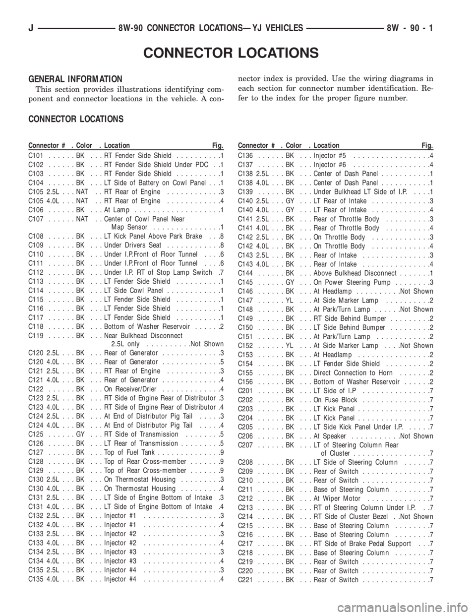
CONNECTOR LOCATIONS
GENERAL INFORMATION
This section provides illustrations identifying com-
ponent and connector locations in the vehicle. A con-nector index is provided. Use the wiring diagrams in
each section for connector number identification. Re-
fer to the index for the proper figure number.
CONNECTOR LOCATIONS
Connector # . Color . Location Fig.
C101......BK ...RTFender Side Shield..........1
C102......BK ...RTFender Side Shield Under PDC . .1
C103......BK ...RTFender Side Shield..........1
C104......BK ...LTSide of Battery on Cowl Panel . . .1
C105 2.5L . . . NAT . . RT Rear of Engine............3
C105 4.0L . . . NAT . . RT Rear of Engine............4
C106......BK ...AtLamp...................1
C107......NAT ..Center of Cowl Panel Near
Map Sensor...............1
C108......BK ...LTKick Panel Above Park Brake . . .8
C109......BK ...Under Drivers Seat............8
C110......BK ...Under I.P.Front of Floor Tunnel....6
C111......BK ...Under I.P.Front of Floor Tunnel....6
C112......BK ...Under I.P. RT of Stop Lamp Switch .7
C113......BK ...LTFender Side Shield..........1
C114......BK ...LTSide Cowl Panel............1
C115......BK ...LTFender Side Shield..........1
C116......BK ...LTFender Side Shield..........1
C117......BK ...LTFender Side Shield..........1
C118......BK ...Bottom of Washer Reservoir......2
C119......BK ...Near Bulkhead Disconnect
2.5L only..........Not Shown
C120 2.5L . . . BK . . . Rear of Generator.............3
C120 4.0L . . . BK . . . Rear of Generator.............5
C121 2.5L . . . BK . . . RT Rear of Engine............3
C121 4.0L . . . BK . . . Rear of Generator.............4
C122......BK ...OnReceiver/Drier.............4
C123 2.5L . . . BK . . . RT Side of Engine Rear of Distributor .3
C123 4.0L . . . BK . . . RT Side of Engine Rear of Distributor .4
C124 2.5L . . . BK . . . At End of Distributor Pig Tail.....3
C124 4.0L . . . BK . . . At End of Distributor Pig Tail.....4
C125......GY ...RTSide of Transmission........5
C126......BK ...LTRear of Transmission.........5
C127......BK ...TopofFuel Tank..............9
C128......BK ...TopofRear Cross-member.......9
C129......BK ...TopofRear Cross-member.......9
C130 2.5L . . . BK . . . On Thermostat Housing.........3
C130 4.0L . . . BK . . . On Thermostat Housing.........4
C131 2.5L . . . BK . . . LT Side of Engine Bottom of Intake .3
C131 4.0L . . . BK . . . LT Side of Engine Bottom of Intake .4
C132 2.5L . . . BK . . . Injector #1.................3
C132 4.0L . . . BK . . . Injector #1.................4
C133 2.5L . . . BK . . . Injector #2.................3
C133 4.0L . . . BK . . . Injector #2.................4
C134 2.5L . . . BK . . . Injector #3.................3
C134 4.0L . . . BK . . . Injector #3.................4
C135 2.5L . . . BK . . . Injector #4.................3
C135 4.0L . . . BK . . . Injector #4.................4Connector # . Color . Location Fig.
C136......BK ...Injector #5.................4
C137......BK ...Injector #6.................4
C138 2.5L . . . BK . . . Center of Dash Panel...........1
C138 4.0L . . . BK . . . Center of Dash Panel...........1
C139......BK ...Under Bulkhead LT Side of I.P.....1
C140 2.5L . . . GY . . . LT Rear of Intake.............3
C140 4.0L . . . GY . . . LT Rear of Intake.............4
C141 2.5L . . . BK . . . Rear of Throttle Body..........3
C141 4.0L . . . BK . . . Rear of Throttle Body..........4
C142 2.5L . . . BK . . . On Throttle Body.............3
C142 4.0L . . . BK . . . On Throttle Body.............4
C143 2.5L . . . BK . . . Rear of Intake...............3
C143 4.0L . . . BK . . . Rear of Intake...............4
C144......BK ...Above Bulkhead Disconnect.......1
C145......GY ...OnPower Steering Pump........3
C146......BK ...AtHeadlamp..........Not Shown
C147......YL ...AtSide Marker Lamp..........2
C148......BK ...AtPark/Turn Lamp......Not Shown
C149......BK ...RTSide Behind Bumper.........2
C150......BK ...LTSide Behind Bumper.........2
C151......BK ...AtPark/Turn Lamp............2
C152......YL ...AtSide Marker Lamp. . . .Not Shown
C153......BK ...AtHeadlamp................2
C154......BK ...LTFender Side Shield..........2
C155......BK ...Direct Connection to Horn.......2
C156......BK ...Bottom of Washer Reservoir......2
C201......BK ...LTSide of I.P...............7
C202......BK ...OnFuse Block...............7
C203......BK ...LTKick Panel................7
C204......BK ...LTKick Panel................7
C205......BK ...LTSide Kick Panel Under I.P......7
C206......BK ...AtSpeaker...........Not Shown
C207......BK ...LTofSteering Column Rear
of Cluster.................7
C208......BK ...LTSide of Steering Column......7
C209......BK ...Rear of Switch...............7
C210......BK ...Rear of Switch...............7
C211......BK ...Base of Steering Column........7
C212......BK ...AtWiper Motor..............7
C213......BK ...RTofSteering Column Under I.P. . .7
C214......BK ...RTSide of Cluster Bezel . .Not Shown
C215......BK ...Base of Steering Column........7
C216......BK ...Base of Steering Column........7
C217......BK ...RTSide of Brake Pedal Support . . .7
C218......BK ...Base of Steering Column........7
C219......BK ...Rear of Switch...............7
C220......BK ...Rear of Switch...............7
C221......BK ...Rear of Switch...............7
J8W-90 CONNECTOR LOCATIONSÐYJ VEHICLES 8W - 90 - 1
Page 1263 of 2158
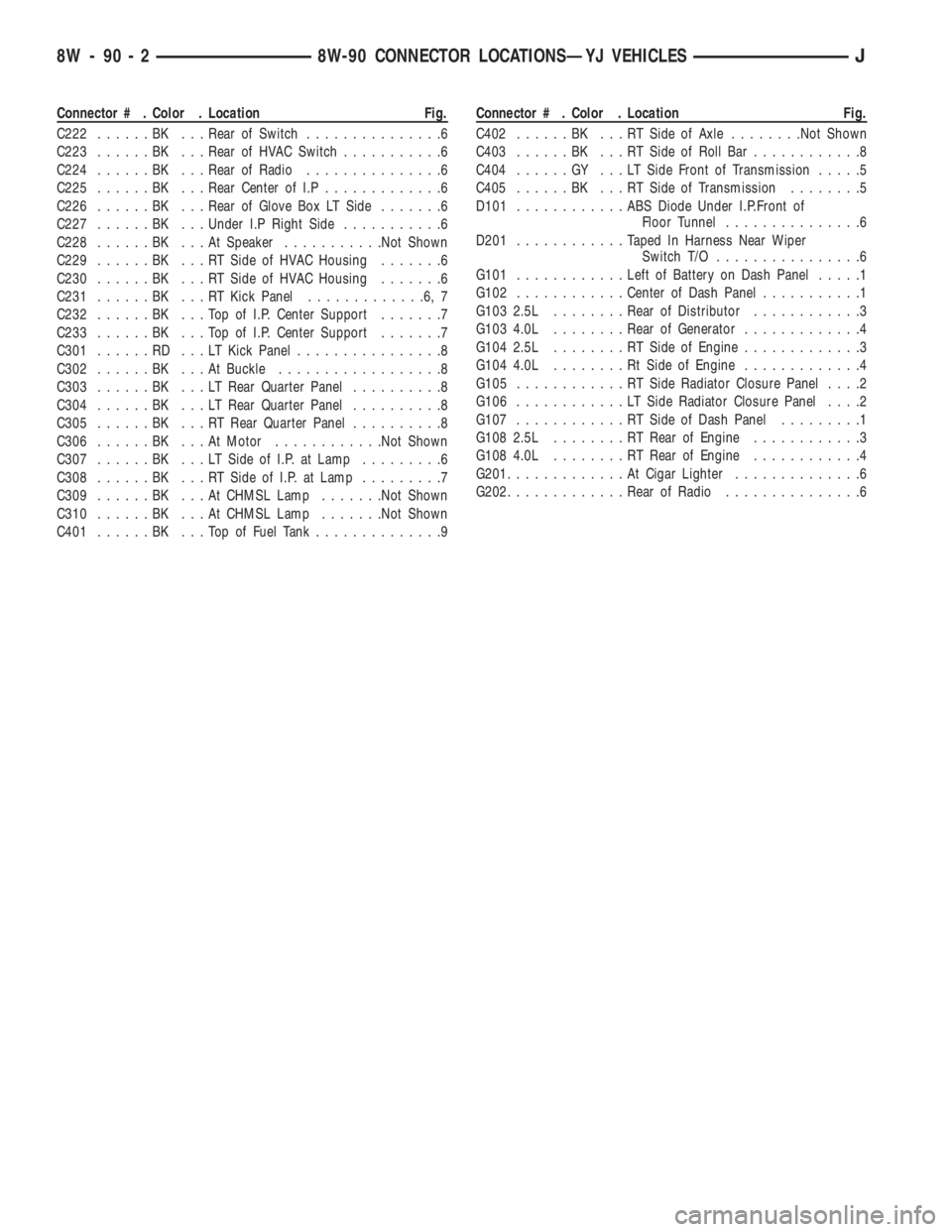
Connector # . Color . Location Fig.
C222......BK ...Rear of Switch...............6
C223......BK ...Rear of HVAC Switch...........6
C224......BK ...Rear of Radio...............6
C225......BK ...Rear Center of I.P.............6
C226......BK ...Rear of Glove Box LT Side.......6
C227......BK ...Under I.P Right Side...........6
C228......BK ...AtSpeaker...........Not Shown
C229......BK ...RTSide of HVAC Housing.......6
C230......BK ...RTSide of HVAC Housing.......6
C231......BK ...RTKick Panel.............6,7
C232......BK ...TopofI.P.Center Support.......7
C233......BK ...TopofI.P.Center Support.......7
C301......RD ...LTKick Panel................8
C302......BK ...AtBuckle..................8
C303......BK ...LTRear Quarter Panel..........8
C304......BK ...LTRear Quarter Panel..........8
C305......BK ...RTRear Quarter Panel..........8
C306......BK ...AtMotor............Not Shown
C307......BK ...LTSide of I.P. at Lamp.........6
C308......BK ...RTSide of I.P. at Lamp.........7
C309......BK ...AtCHMSL Lamp.......Not Shown
C310......BK ...AtCHMSL Lamp.......Not Shown
C401......BK ...TopofFuel Tank..............9Connector # . Color . Location Fig.
C402......BK ...RTSide of Axle........Not Shown
C403......BK ...RTSide of Roll Bar............8
C404......GY ...LTSide Front of Transmission.....5
C405......BK ...RTSide of Transmission........5
D101............ABSDiode Under I.P.Front of
Floor Tunnel...............6
D201............Taped In Harness Near Wiper
Switch T/O................6
G101............Left of Battery on Dash Panel.....1
G102............Center of Dash Panel...........1
G103 2.5L . .......Rear of Distributor............3
G103 4.0L . .......Rear of Generator.............4
G104 2.5L . .......RTSide of Engine.............3
G104 4.0L . .......RtSide of Engine.............4
G105............RTSide Radiator Closure Panel....2
G106............LTSide Radiator Closure Panel....2
G107............RTSide of Dash Panel.........1
G108 2.5L . .......RTRear of Engine............3
G108 4.0L . .......RTRear of Engine............4
G201.............AtCigar Lighter..............6
G202.............Rear of Radio...............6
8W - 90 - 2 8W-90 CONNECTOR LOCATIONSÐYJ VEHICLESJ