2.5 engine JEEP YJ 1995 Service And Workshop Manual
[x] Cancel search | Manufacturer: JEEP, Model Year: 1995, Model line: YJ, Model: JEEP YJ 1995Pages: 2158, PDF Size: 81.9 MB
Page 1266 of 2158
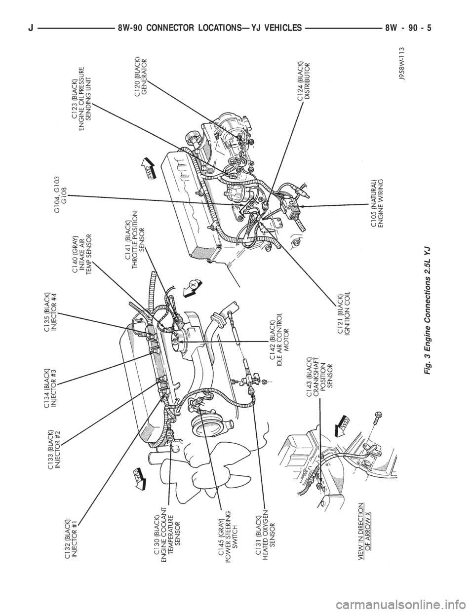
Fig. 3 Engine Connections 2.5L YJ
J8W-90 CONNECTOR LOCATIONSÐYJ VEHICLES 8W - 90 - 5
Page 1273 of 2158
SPLICE LOCATIONS
GENERAL INFORMATION
This section provides illustrations identifying the
general location of the splices in this vehicle. A splice
index is provided. Use the wiring diagrams in each
section for splice number identification. Refer to the
index for the proper splice number.
SPLICE LOCATIONS
Splice
NumberLocations Fig.
S101 Near PDC T/O.....................1
S102 Near T/O for Engine Wiring.............1
S103 RT Dash Panel Near T/o for Ground.......1
S104 Near T/O for MAP Sensor..............1
S105 Near T/O for MAP Sensor..............1
S106 Left Side of MAP Sensor..............1
S107 In ABS Wiring T/O Near Grommet........1
S108 In ABS Wiring T/O Near Grommet........1
S109 Above Brake Booster.................1
S110 Rear of Generator...................3
S111 2.5L RT Side of Valve Cover...............4
S111 4.0L RT Side of Valve Cover...............3
S112 Near T/O for PRNDL Switch............5
S113 Between Inj #2 and Inj #3.............3
S114 Near T/O for Throttle Body Wiring........3
S115 Above Bulkhead Connector.............1
S116 Above Bulkhead Connector.............1
S117 Near Data Link T/O..................1
S118 Near Data Link T/O..................1
S119 Near Data Link T/O..................1
S120 4.0L RT Side of Valve Cover...............3
S121 2.5L RT Side of Valve Cover...............4
S122 Near T/O for RT PK/TURN Lamp.........2
S123 Near T/O for RT Fog Lamp.............2
S124 Near T/O for LT Fog Lamp.............2
S125 Near T/O for LT PK/TURN Lamp.........2Splice
NumberLocations Fig.
S126 Near T/O for Headlamp...............2
S127 Near T/O for Headlamp...............2
S128 Near T/O for Headlamp...............2
S129 Near Horn T/O.....................2
S201 Near T/O for Dimmer Switch............7
S202 Near T/O for Dimmer Switch............7
S203 Near T/O for Dimmer Switch............7
S204 Near T/O for Dimmer Switch............7
S205 Near T/O for Wiper Switch.............7
S206 Near T/O for Wiper Switch.............7
S207 Near Panel Illumination T/O.............7
S208 Near Panel Illumination T/O.............7
S209 Near Panel Illumination T/O.............7
S210 Near Panel Illumination T/O.............7
S211 Near T/O for Ignition Switch............7
S212 Near T/O for Ignition Switch............7
S213 Near T/O for Radio..................6
S301 Near T/O for Park Brake Switch..........8
S302 Near T/O for Park Brake Switch..........8
S303 Near Grommet LT Rear Quarter Panel......8
S304 Near LT Rear Tail Lamp T/O............8
S305 RT Rear Quarter Panel Near Tail Lamp.....8
S306 Near T/O for Dome Lamp.......Not Shown
S307 In CHMSL Jumper Harness......Not Shown
S308 In CHMSL Jumper Harness......Not Shown
J8W-95 SPLICE LOCATIONSÐYJ VEHICLES 8W - 95 - 1
Page 1277 of 2158
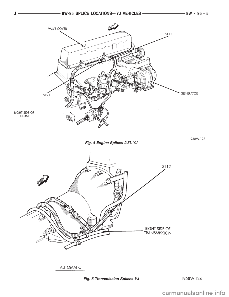
Fig. 4 Engine Splices 2.5L YJ
Fig. 5 Transmission Splices YJ
J8W-95 SPLICE LOCATIONSÐYJ VEHICLES 8W - 95 - 5
Page 1280 of 2158
ENGINES
CONTENTS
page page
LUBRICATION SYSTEM................... 37
LUBRICATION SYSTEM................... 79
2.5L ENGINE SERVICE PROCEDURES....... 134.0L ENGINE SERVICE PROCEDURES....... 55
ENGINE DIAGNOSIS...................... 5
STANDARD SERVICE PROCEDURES......... 1
STANDARD SERVICE PROCEDURES
INDEX
page page
Engine Performance........................ 2
Form-In-Place Gaskets...................... 1
Honing Cylinder Bores...................... 2
Hydrostatic Lock........................... 4Measuring with Plastigage.................... 3
Repair Damaged or Worn Threads............. 4
Service Engine Assembly (Short Block).......... 4
FORM-IN-PLACE GASKETS
There are several places where form-in-place gas-
kets are used on the engine.DO NOT use form-in-
place gasket material unless specified.Care
must be taken when applying form-in-place gaskets.
Bead size, continuity and location are of great impor-
tance. Too thin a bead can result in leakage while too
much can result in spill-over. A continuous bead of
the proper width is essential to obtain a leak-free
joint.
Two types of form-in-place gasket materials are
used in the engine area (Mopar Silicone Rubber Ad-
hesive Sealant and Mopar Gasket Maker). Each have
different properties and cannot be used interchange-
ably.
MOPAR SILICONE RUBBER ADHESIVE
SEALANT
Mopar Silicone Rubber Adhesive Sealant, normally
black in color, is available in 3 ounce tubes. Moisture
in the air causes the sealant material to cure. This
material is normally used on flexible metal flanges.
It has a shelf life of a year and will not properly cure
if over aged. Always inspect the package for the ex-
piration date before use.
MOPAR GASKET MAKER
Mopar Gasket Maker, normally red in color, is
available in 6 cc tubes. This anaerobic type gasket
material cures in the absence of air when squeezedbetween smooth machined metallic surfaces. It will
not cure if left in the uncovered tube. DO NOT use
on flexible metal flanges.
SURFACE PREPARATION
Parts assembled with form-in-place gaskets may be
disassembled without unusual effort. In some in-
stances, it may be necessary to lightly tap the part
with a mallet or other suitable tool to break the seal
between the mating surfaces. A flat gasket scraper
may also be lightly tapped into the joint but care
must be taken not to damage the mating surfaces.
Scrape or wire brush all gasket surfaces to remove
all loose material. Inspect stamped parts to ensure
gasket rails are flat. Flatten rails with a hammer on
a flat plate, if required. Gasket surfaces must be free
of oil and dirt. Make sure the old gasket material is
removed from blind attaching holes.
GASKET APPLICATION
Assembling parts using a form-in-place gasket re-
quires care.
Mopar Silicone Rubber Adhesive Sealant should be
applied in a continuous bead approximately 3 mm
(0.12 inch) in diameter. All mounting holes must be
circled. For corner sealing,a3or6mm(1/8 or 1/4
inch) drop is placed in the center of the gasket con-
tact area. Uncured sealant may be removed with a
shop towel. Components should be torqued in place
while the sealant is still wet to the touch (within 10
JENGINES 9 - 1
Page 1282 of 2158
CAUTION: DO NOT use engine or transmission oil,
mineral spirits or kerosene.
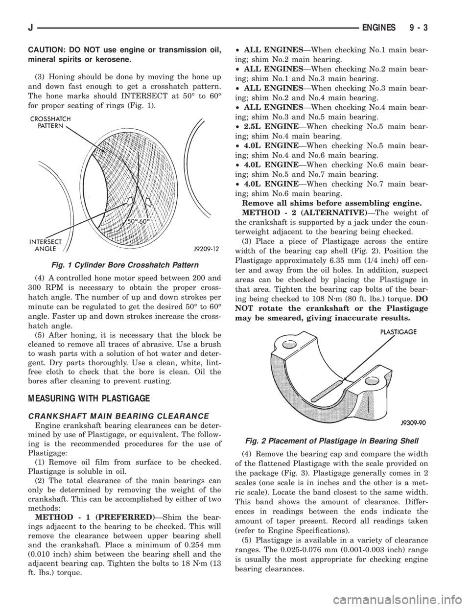
(3) Honing should be done by moving the hone up
and down fast enough to get a crosshatch pattern.
The hone marks should INTERSECT at 50É to 60É
for proper seating of rings (Fig. 1).
(4) A controlled hone motor speed between 200 and
300 RPM is necessary to obtain the proper cross-
hatch angle. The number of up and down strokes per
minute can be regulated to get the desired 50É to 60É
angle. Faster up and down strokes increase the cross-
hatch angle.
(5) After honing, it is necessary that the block be
cleaned to remove all traces of abrasive. Use a brush
to wash parts with a solution of hot water and deter-
gent. Dry parts thoroughly. Use a clean, white, lint-
free cloth to check that the bore is clean. Oil the
bores after cleaning to prevent rusting.
MEASURING WITH PLASTIGAGE
CRANKSHAFT MAIN BEARING CLEARANCE
Engine crankshaft bearing clearances can be deter-
mined by use of Plastigage, or equivalent. The follow-
ing is the recommended procedures for the use of
Plastigage:
(1) Remove oil film from surface to be checked.
Plastigage is soluble in oil.
(2) The total clearance of the main bearings can
only be determined by removing the weight of the
crankshaft. This can be accomplished by either of two
methods:
METHOD - 1 (PREFERRED)ÐShim the bear-
ings adjacent to the bearing to be checked. This will
remove the clearance between upper bearing shell
and the crankshaft. Place a minimum of 0.254 mm
(0.010 inch) shim between the bearing shell and the
adjacent bearing cap. Tighten the bolts to 18 Nzm (13
ft. lbs.) torque.²ALL ENGINESÐWhen checking No.1 main bear-
ing; shim No.2 main bearing.
²ALL ENGINESÐWhen checking No.2 main bear-
ing; shim No.1 and No.3 main bearing.
²ALL ENGINESÐWhen checking No.3 main bear-
ing; shim No.2 and No.4 main bearing.
²ALL ENGINESÐWhen checking No.4 main bear-
ing; shim No.3 and No.5 main bearing.
²2.5L ENGINEÐWhen checking No.5 main bear-
ing; shim No.4 main bearing.
²4.0L ENGINEÐWhen checking No.5 main bear-
ing; shim No.4 and No.6 main bearing.
²4.0L ENGINEÐWhen checking No.6 main bear-
ing; shim No.5 and No.7 main bearing.
²4.0L ENGINEÐWhen checking No.7 main bear-
ing; shim No.6 main bearing.
Remove all shims before assembling engine.
METHOD - 2 (ALTERNATIVE)ÐThe weight of
the crankshaft is supported by a jack under the coun-
terweight adjacent to the bearing being checked.
(3) Place a piece of Plastigage across the entire
width of the bearing cap shell (Fig. 2). Position the
Plastigage approximately 6.35 mm (1/4 inch) off cen-
ter and away from the oil holes. In addition, suspect
areas can be checked by placing the Plastigage in
that area. Tighten the bearing cap bolts of the bear-
ing being checked to 108 Nzm (80 ft. lbs.) torque.DO
NOT rotate the crankshaft or the Plastigage
may be smeared, giving inaccurate results.
(4) Remove the bearing cap and compare the width
of the flattened Plastigage with the scale provided on
the package (Fig. 3). Plastigage generally comes in 2
scales (one scale is in inches and the other is a met-
ric scale). Locate the band closest to the same width.
This band shows the amount of clearance. Differ-
ences in readings between the ends indicate the
amount of taper present. Record all readings taken
(refer to Engine Specifications).
(5) Plastigage is available in a variety of clearance
ranges. The 0.025-0.076 mm (0.001-0.003 inch) range
is usually the most appropriate for checking engine
bearing clearances.
Fig. 1 Cylinder Bore Crosshatch Pattern
Fig. 2 Placement of Plastigage in Bearing Shell
JENGINES 9 - 3
Page 1285 of 2158
CYLINDER COMBUSTION PRESSURE LEAKAGE
TEST
The combustion pressure leakage test provides an
accurate means for determining engine condition.
Combustion pressure leakage testing will detect:
²Exhaust and intake valve leaks (improper seat-
ing).
²Leaks between adjacent cylinders or into water
jacket.
²Any causes for combustion/compression pressure
loss.
WARNING: DO NOT REMOVE THE RADIATOR CAP
WITH THE SYSTEM HOT AND UNDER PRESSURE
BECAUSE SERIOUS BURNS FROM COOLANT CAN
OCCUR.
Check the coolant level and fill as required. DO
NOT install the radiator cap.
Start and operate the engine until it attains nor-
mal operating temperature, then turn the engine
OFF.
Remove the spark plugs.
Remove the oil filler cap.
Remove the air cleaner.
Calibrate the tester according to the manufactur-
er's instructions. The shop air source for testing
should maintain 483 kPa (70 psi) minimum, 1 379
kPa (200 psi) maximum and 552 kPa (80 psi) recom-
mended.
Perform the test procedures on each cylinder ac-
cording to the tester manufacturer's instructions.
While testing, listen for pressurized air escaping
through the throttle body, tailpipe and oil filler cap
opening. Check for bubbles in the radiator coolant.
All gauge pressure indications should be equal,
with no more than 25% leakage.
FOR EXAMPLE:At 552 kPa (80 psi) input pres-
sure, a minimum of 414 kPa (60 psi) should be main-
tained in the cylinder.
Refer to the Cylinder Combustion Pressure Leak-
age Test Diagnosis chart.
INSPECTION (ENGINE OIL LEAKS IN GENERAL)
Begin with a through visual inspection of the en-
gine, particularly at the area of the suspected leak. If
an oil leak source is not readily identifiable, the fol-
lowing steps should be followed:
(1) Do not clean or degrease the engine at this
time because some solvents may cause rubber to
swell, temporarily stopping the leak.
(2) Add an oil soluble dye (use as recommended by
manufacturer). Start the engine and let idle for ap-
proximately 15 minutes. Check the oil dipstick to
make sure the dye is thoroughly mixed as indicated
with a bright yellow color under a black light.(3) Using a black light, inspect the entire engine
for fluorescent dye, particularly at the suspected area
of oil leak. If the oil leak is found and identified, re-
pair per service manual instructions.
(4) If dye is not observed, drive the vehicle at var-
ious speeds for approximately 24km (15 miles), and
repeat step (3).
If the oil leak source is not positively identi-
fied at this time, proceed with the air leak detec-
tion test method as follows:
(1) Disconnect the breather cap to air cleaner hose
at the breather cap end. Cap or plug breather cap
nipple.
(2) Remove the PCV valve from the cylinder head
cover. Cap or plug the PCV valve grommet.
(3) Attach an air hose with pressure gauge and
regulator to the dipstick tube.
CAUTION: Do not subject the engine assembly to
more than 20.6 kpa (3 PSI) of test pressure.
(4) Gradually apply air pressure from 1 psi to 2.5
psi maximum while applying soapy water at the sus-
pected source. Adjust the regulator to the suitable
test pressure that provide the best bubbles which
will pinpoint the leak source. If the oil leak is de-
tected and identified, repair per service manual pro-
cedures.
(5) If the leakage occurs at the rear oil seal area,
refer to the section, Inspection for Rear Seal Area
Leak.
(6) If no leaks are detected, turn off the air supply
and remove the air hose and all plugs and caps. In-
stall the PCV valve and breather cap hose. Proceed
to step 7.
(7) Clean the oil off the suspect oil leak area using
a suitable solvent. Drive the vehicle at various
speeds approximately 24 km (15 miles). Inspect the
engine for signs of an oil leak by using a black light.
INSPECTION FOR REAR SEAL AREA LEAKS
Since it is sometimes difficult to determine the
source of an oil leak in the rear seal area of the en-
gine, a more involved inspection is necessary. The fol-
lowing steps should be followed to help pinpoint the
source of the leak.
If the leakage occurs at the crankshaft rear oil seal
area:
(1) Disconnect the battery.
(2) Raise the vehicle.
(3) Remove torque converter or clutch housing
cover and inspect rear of block for evidence of oil.
Use a black light to check for the oil leak:
(a) Circular spray pattern generally indicates
seal leakage or crankshaft damage.
(b) Where leakage tends to run straight down,
possible causes are a porous block, distributor seal,
camshaft bore cup plugs oil galley pipe plugs, oil
9 - 6 ENGINESJ
Page 1292 of 2158
2.5L ENGINE SERVICE PROCEDURES
INDEX
page page
Camshaft............................... 32
Camshaft Pin Replacement.................. 34
Engine AssemblyÐXJ Vehicles............... 18
Engine AssemblyÐYJ Vehicles............... 20
Engine Cylinder Head...................... 25
Engine Cylinder Head Cover................. 22
Engine Damper........................... 17
Engine MountÐRear....................... 16
Engine MountsÐFront..................... 14
General Information....................... 13
Hydraulic Tappets......................... 24OilPan ................................. 36
Rocker Arms and Push Rods................ 23
Timing Case Cover........................ 31
Timing Case Cover Oil Seal Replacement....... 30
Timing Chain and Sprockets................. 31
Valve Component ReplaceÐCylinder Head Not
Removed.............................. 23
Valve Springs and Oil Seals................. 23
Valve Timing............................. 30
Valves and Valve Springs................... 27
Vibration Damper......................... 30
GENERAL INFORMATION
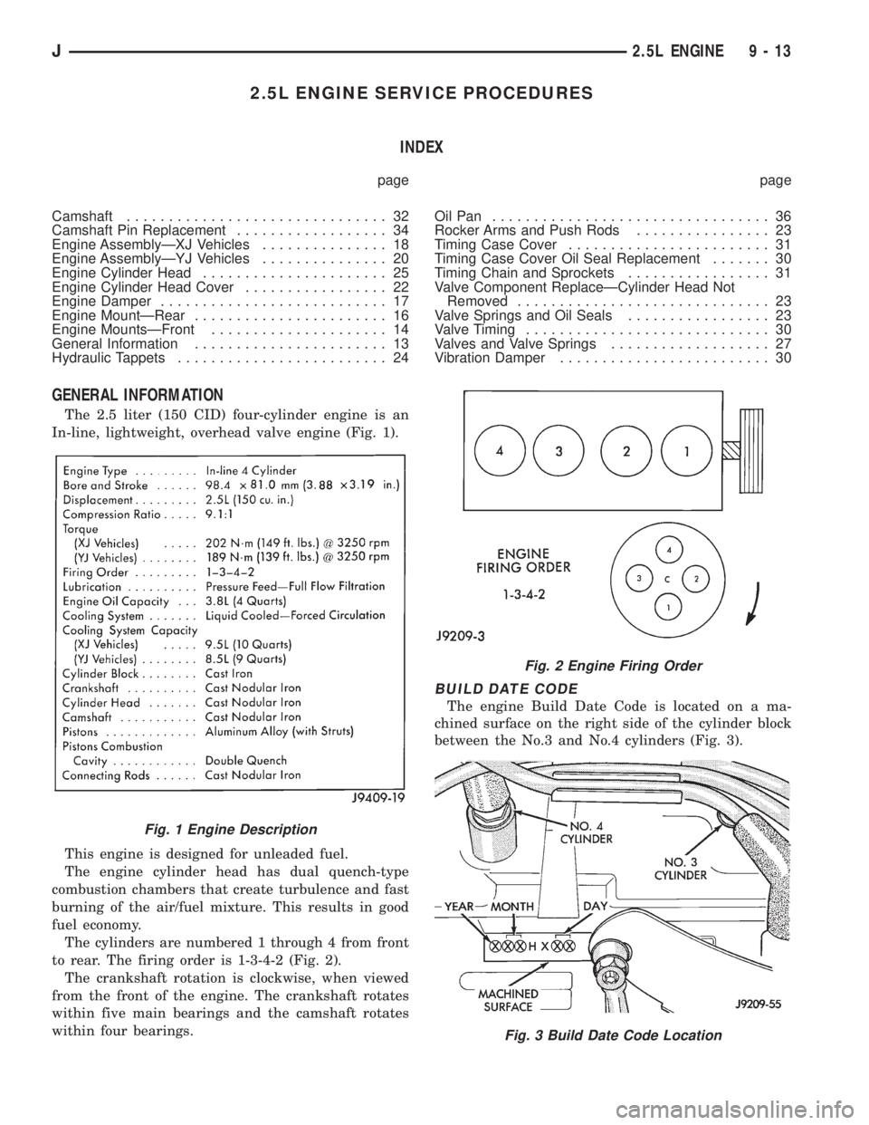
The 2.5 liter (150 CID) four-cylinder engine is an
In-line, lightweight, overhead valve engine (Fig. 1).
This engine is designed for unleaded fuel.
The engine cylinder head has dual quench-type
combustion chambers that create turbulence and fast
burning of the air/fuel mixture. This results in good
fuel economy.
The cylinders are numbered 1 through 4 from front
to rear. The firing order is 1-3-4-2 (Fig. 2).
The crankshaft rotation is clockwise, when viewed
from the front of the engine. The crankshaft rotates
within five main bearings and the camshaft rotates
within four bearings.
BUILD DATE CODE
The engine Build Date Code is located on a ma-
chined surface on the right side of the cylinder block
between the No.3 and No.4 cylinders (Fig. 3).
Fig. 1 Engine Description
Fig. 2 Engine Firing Order
Fig. 3 Build Date Code Location
J2.5L ENGINE 9 - 13
Page 1293 of 2158

The digits of the code identify:
(1) 1st DigitÐThe year (4 = 1994).
(2) 2nd & 3rd DigitsÐThe month (01 - 12).
(3) 4th & 5th DigitsÐThe engine type/fuel system/
compression ratio (HX = A 2.5 liter (150 CID) 9.1:1
compression ratio engine with a multi-point fuel in-
jection system).
(4) 6th & 7th DigitsÐThe day of engine build (01 -
31).
FOR EXAMPLE:Code * 401HX23 * identifies a
2.5 liter (150 CID) engine with a multi-point fuel in-
jection system, 9.1:1 compression ratio and built on
January 23, 1994.
OVERSIZE AND UNDERSIZE COMPONENT
CODES
Some engines may be built with oversize or under-
size components such as:
²Oversize cylinder bores.
²Oversize camshaft bearing bores.
²Undersize crankshaft main bearing journals.
²Undersize connecting rod journals.
These engines are identified by a letter code (Fig.
4) stamped on the oil filter boss near the distributor
(Fig. 5).
ENGINE MOUNTSÐFRONT
The front mounts support the engine at each side.
These supports are made of resilient rubber.
REMOVALÐXJ VEHICLES
(1) Disconnect negative cable from battery.
(2) Raise the vehicle.
(3) Support the engine.
(4) Remove through bolt nut (Fig. 6). DO NOT re-
move the through bolt.
(5) Remove the retaining bolts and nuts from the
support cushions (Fig. 6).
(6) Remove the through bolt.
(7) Remove the support cushions.
INSTALLATIONÐXJ VEHICLES
(1) If the engine support bracket was removed, po-
sition the LEFT bracket (Fig. 6) and the RIGHT
bracket with generator brace (Fig. 7) onto the cylin-
der block. Install the bolts and stud nuts.
(a) RIGHT SIDE (Fig. 7)ÐTighten the bolts to 61
Nzm (45 ft. lbs.) torque. Tighten the stud nuts to 46
Nzm (34 ft. lbs.) torque.
(b) LEFT SIDE (Fig. 6)ÐTighten the bolts to 61
Nzm (45 ft. lbs.) torque.
(2) If the support cushion brackets were removed,
position the brackets onto the lower front sill (Figs. 6
and 8). Install the bolts and stud nuts. Tighten the
bolts to 54 Nzm (40 ft. lbs.) torque and the stud nuts
to 41 Nzm (30 ft. lbs.) torque.
(3) Place the support cushions onto the support
cushion brackets (Fig. 6). Tighten the right support
cushion nuts to 65 Nzm (48 ft. lbs.) torque. Tighten
the left support cushion bolt and nut to 41 Nzm (30
ft. lbs.) torque.
Fig. 4 Oversize and Undersize Component Codes
Fig. 5 Oversize and Undersize Component Code
Location
9 - 14 2.5L ENGINEJ
Page 1294 of 2158
(4) Install the through bolt and the retaining nut
(Fig. 6). Tighten the through bolt nut to 65 Nzm (48
ft. lbs.) torque.
(5) Remove the engine support.
(6) Lower the vehicle.
(7) Connect negative cable to battery.
REMOVALÐYJ VEHICLES
(1) Disconnect negative cable from battery.
(2) Raise the vehicle.(3) Support the engine.
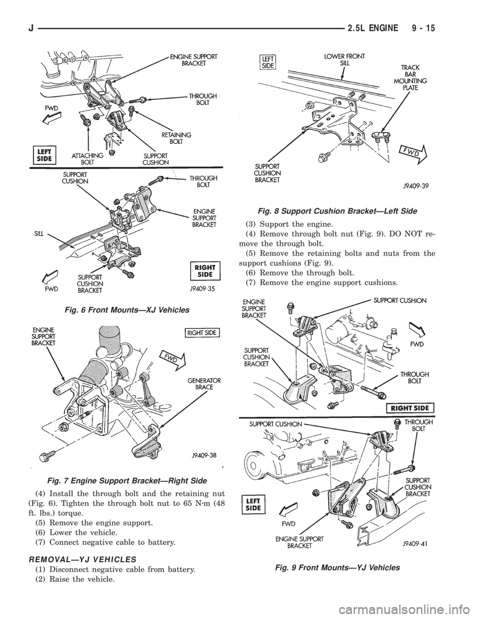
(4) Remove through bolt nut (Fig. 9). DO NOT re-
move the through bolt.
(5) Remove the retaining bolts and nuts from the
support cushions (Fig. 9).
(6) Remove the through bolt.
(7) Remove the engine support cushions.
Fig. 6 Front MountsÐXJ Vehicles
Fig. 7 Engine Support BracketÐRight Side
Fig. 8 Support Cushion BracketÐLeft Side
Fig. 9 Front MountsÐYJ Vehicles
J2.5L ENGINE 9 - 15
Page 1295 of 2158
INSTALLATIONÐYJ VEHICLES
(1) If the engine support bracket was removed, po-
sition the bracket onto the block and install the at-
taching bolts (Fig. 9). Tighten the bolts to 62 Nzm (46
ft. lbs.) torque.
(2) Place the support cushion on the support cush-
ion bracket (Fig. 9). Install the support cushion re-
taining bolts and nuts. Tighten the bolts and nuts to
52 Nzm (38 ft. lbs.) torque.
(3) Install the through bolt and the retaining nut
(Fig. 9). Tighten the through bolt nut to 69 Nzm (51
ft. lbs.) torque.
(4) Remove the engine support.
(5) Lower the vehicle.
(6) Connect negative cable to battery.
ENGINE MOUNTÐREAR
A resilient rubber cushion supports the transmis-
sion at the rear between the transmission extension
housing and the rear support crossmember or skid
plate.
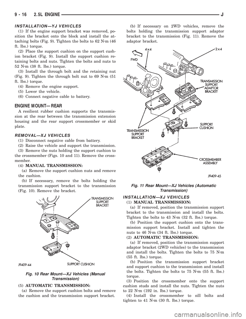
REMOVALÐXJ VEHICLES
(1) Disconnect negative cable from battery.
(2) Raise the vehicle and support the transmission.
(3) Remove the nuts holding the support cushion to
the crossmember (Figs. 10 and 11). Remove the cross-
member.
(4)MANUAL TRANSMISSION:
(a) Remove the support cushion nuts and remove
the cushion.
(b) If necessary, remove the bolts holding the
transmission support bracket to the transmission
(Fig. 10). Remove the bracket.
(5)AUTOMATIC TRANSMISSION:
(a) Remove the support cushion bolts and remove
the cushion and the transmission support bracket.(b) If necessary on 2WD vehicles, remove the
bolts holding the transmission support adaptor
bracket to the transmission (Fig. 11). Remove the
adaptor bracket.
INSTALLATIONÐXJ VEHICLES
(1)MANUAL TRANSMISSION:
(a) If removed, position the transmission support
bracket to the transmission and install the bolts.
Tighten the bolts to 43 Nzm (32 ft. lbs.) torque.
(b) Position the support cushion onto the trans-
mission support bracket. Install and tighten the
nuts to 46 Nzm (34 ft. lbs.) torque.
(2)AUTOMATIC TRANSMISSION:
(a) If removed, position the transmission support
adaptor bracket (2WD vehicles) to the transmission
and install the bolts. Tighten the bolts to 75 Nzm
(55 ft. lbs.) torque.
(b) Position the transmission support bracket
and support cushion to the transmission and install
the bolts. Tighten the bolts to 75 Nzm (55 ft. lbs.)
torque.
(3) Position the crossmember onto the support
cushion studs and install the nuts. Tighten the nuts
to 22 Nzm (192 in. lbs.) torque.
(4) Install the crossmember to sill bolts and
tighten to 41 Nzm (30 ft. lbs.) torque.
Fig. 10 Rear MountÐXJ Vehicles (Manual
Transmission)
Fig. 11 Rear MountÐXJ Vehicles (Automatic
Transmission)
9 - 16 2.5L ENGINEJ