JEEP YJ 1995 Service And Repair Manual
Manufacturer: JEEP, Model Year: 1995, Model line: YJ, Model: JEEP YJ 1995Pages: 2158, PDF Size: 81.9 MB
Page 441 of 2158
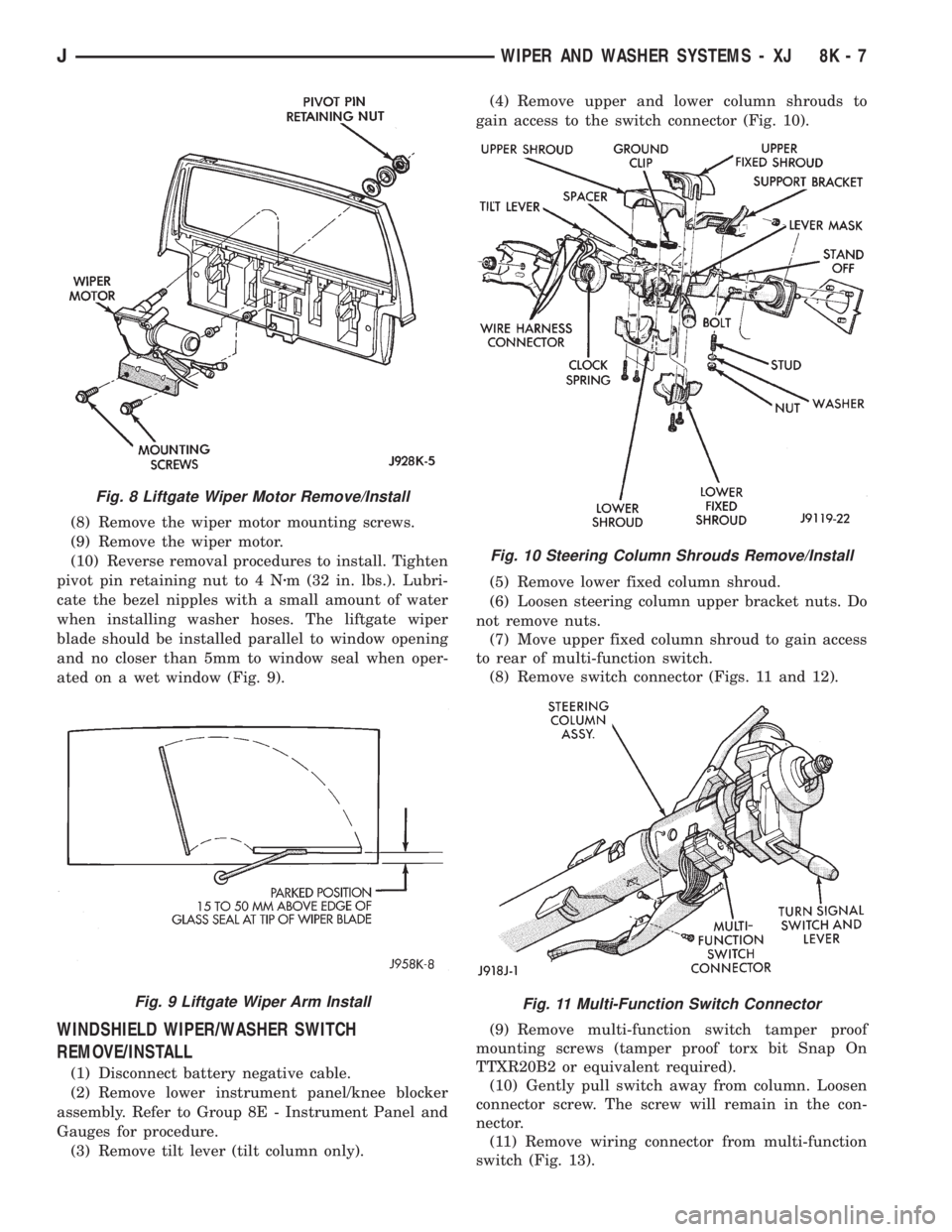
(8) Remove the wiper motor mounting screws.
(9) Remove the wiper motor.
(10) Reverse removal procedures to install. Tighten
pivot pin retaining nut to 4 Nzm (32 in. lbs.). Lubri-
cate the bezel nipples with a small amount of water
when installing washer hoses. The liftgate wiper
blade should be installed parallel to window opening
and no closer than 5mm to window seal when oper-
ated on a wet window (Fig. 9).
WINDSHIELD WIPER/WASHER SWITCH
REMOVE/INSTALL
(1) Disconnect battery negative cable.
(2) Remove lower instrument panel/knee blocker
assembly. Refer to Group 8E - Instrument Panel and
Gauges for procedure.
(3) Remove tilt lever (tilt column only).(4) Remove upper and lower column shrouds to
gain access to the switch connector (Fig. 10).
(5) Remove lower fixed column shroud.
(6) Loosen steering column upper bracket nuts. Do
not remove nuts.
(7) Move upper fixed column shroud to gain access
to rear of multi-function switch.
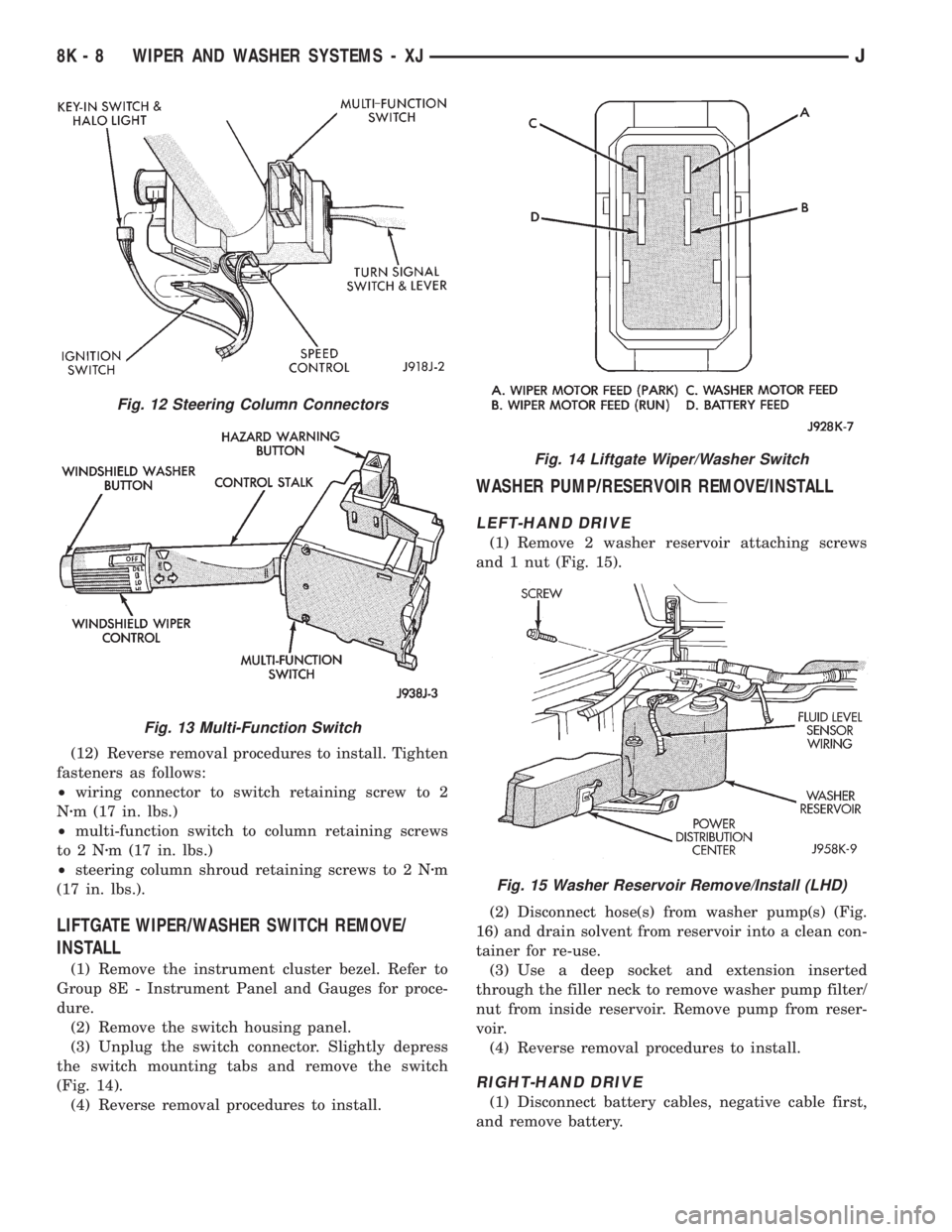
(8) Remove switch connector (Figs. 11 and 12).
(9) Remove multi-function switch tamper proof
mounting screws (tamper proof torx bit Snap On
TTXR20B2 or equivalent required).
(10) Gently pull switch away from column. Loosen
connector screw. The screw will remain in the con-
nector.
(11) Remove wiring connector from multi-function
switch (Fig. 13).
Fig. 8 Liftgate Wiper Motor Remove/Install
Fig. 9 Liftgate Wiper Arm Install
Fig. 10 Steering Column Shrouds Remove/Install
Fig. 11 Multi-Function Switch Connector
JWIPER AND WASHER SYSTEMS - XJ 8K - 7
Page 442 of 2158
(12) Reverse removal procedures to install. Tighten
fasteners as follows:
²wiring connector to switch retaining screw to 2
Nzm (17 in. lbs.)
²multi-function switch to column retaining screws
to2Nzm (17 in. lbs.)
²steering column shroud retaining screws to 2 Nzm
(17 in. lbs.).
LIFTGATE WIPER/WASHER SWITCH REMOVE/
INSTALL
(1) Remove the instrument cluster bezel. Refer to
Group 8E - Instrument Panel and Gauges for proce-
dure.
(2) Remove the switch housing panel.
(3) Unplug the switch connector. Slightly depress
the switch mounting tabs and remove the switch
(Fig. 14).
(4) Reverse removal procedures to install.
WASHER PUMP/RESERVOIR REMOVE/INSTALL
LEFT-HAND DRIVE
(1) Remove 2 washer reservoir attaching screws
and 1 nut (Fig. 15).
(2) Disconnect hose(s) from washer pump(s) (Fig.
16) and drain solvent from reservoir into a clean con-
tainer for re-use.
(3) Use a deep socket and extension inserted
through the filler neck to remove washer pump filter/
nut from inside reservoir. Remove pump from reser-
voir.
(4) Reverse removal procedures to install.
RIGHT-HAND DRIVE
(1) Disconnect battery cables, negative cable first,
and remove battery.
Fig. 12 Steering Column Connectors
Fig. 13 Multi-Function Switch
Fig. 14 Liftgate Wiper/Washer Switch
Fig. 15 Washer Reservoir Remove/Install (LHD)
8K - 8 WIPER AND WASHER SYSTEMS - XJJ
Page 443 of 2158
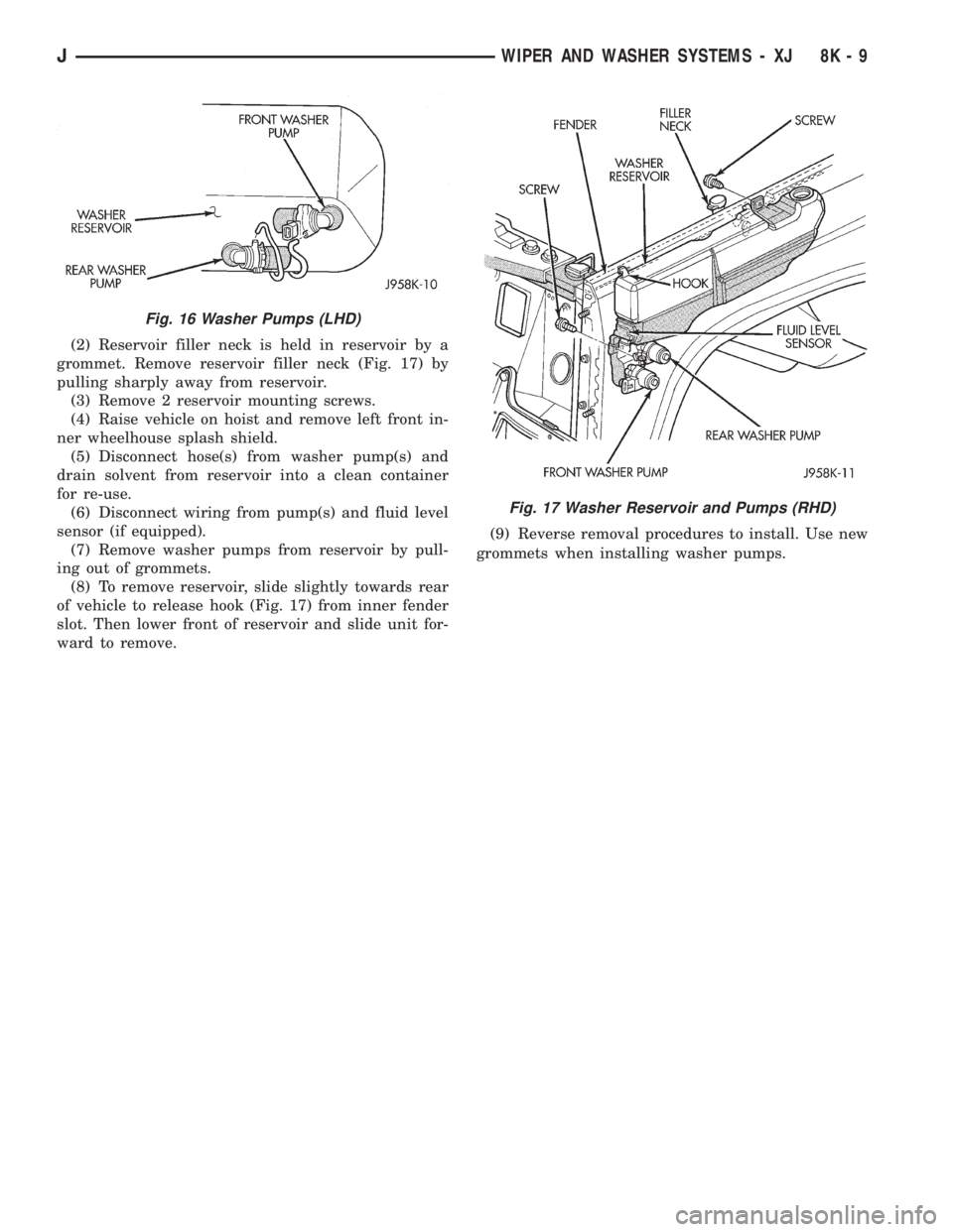
(2) Reservoir filler neck is held in reservoir by a
grommet. Remove reservoir filler neck (Fig. 17) by
pulling sharply away from reservoir.
(3) Remove 2 reservoir mounting screws.
(4) Raise vehicle on hoist and remove left front in-
ner wheelhouse splash shield.
(5) Disconnect hose(s) from washer pump(s) and
drain solvent from reservoir into a clean container
for re-use.
(6) Disconnect wiring from pump(s) and fluid level
sensor (if equipped).
(7) Remove washer pumps from reservoir by pull-
ing out of grommets.
(8) To remove reservoir, slide slightly towards rear
of vehicle to release hook (Fig. 17) from inner fender
slot. Then lower front of reservoir and slide unit for-
ward to remove.(9) Reverse removal procedures to install. Use new
grommets when installing washer pumps.
Fig. 16 Washer Pumps (LHD)
Fig. 17 Washer Reservoir and Pumps (RHD)
JWIPER AND WASHER SYSTEMS - XJ 8K - 9
Page 444 of 2158
GENERAL INFORMATION - YJ
Following are general descriptions of the major
components in the YJ (Wrangler) wiper and washer
systems. Refer to Group 8W - Wiring Diagrams for
complete circuit descriptions and diagrams.
WINDSHIELD WIPER SYSTEM
A two-speed wiper system is standard equipment
on all YJ models. An optional intermittent wipe sys-
tem is available. The standard system allows the
driver to select from two wiper speeds. The optional
intermittent wipe system allows the driver to select
from two wiper speeds or an intermittent wipe fea-
ture that allows a delay between wipes of 2 to 15 sec-
onds. Refer to the owner's manual for more
information on wiper system controls and operation.
The wipers will operate only when the ignition
switch is in the ACCESSORY or ON position. A cir-
cuit breaker in the fuseblock module protects the cir-
cuitry of the wiper system.
WINDSHIELD WASHER SYSTEM
A electrically-operated windshield washer system is
standard equipment on all YJ models. The washers
will operate only when the ignition switch is in the
ACCESSORY or ON position. A circuit breaker in the
fuseblock module protects the circuitry of the washer
system. Refer to the owner's manual for more infor-
mation on washer system controls and operation.
LIFTGATE WIPER/WASHER SYSTEM
A liftgate wiper/washer system is an available op-
tion on YJ models equipped with the optional hard-
top. The liftgate wiper is a fixed cycle wipe system. A
single switch on the instrument panel controls both
the liftgate wiper and washer functions. These sys-
tems will operate only when the ignition switch is in
the ON position. Fuse 1 in the fuseblock module pro-
tects the circuitry of both the liftgate wiper and
washer. Refer to the owner's manual for more infor-
mation on liftgate wiper/washer system controls and
operation.
WIPER ARMS, BLADES, AND ELEMENTS
All YJ models have two 12-inch windshield wiper
blades with replaceable rubber elements (squeegees).
Models with the liftgate wiper option use a single 16-
inch wiper blade with a replaceable rubber element
(squeegee).
Caution should be exercised to protect the rubber
squeegees from any petroleum-based cleaners or con-
taminants, which will rapidly deteriorate the squee-
gee rubber. If squeegees are damaged, worn or
contaminated they must be replaced.
Wiper squeegees exposed to the weather for a long
time tend to lose their wiping effectiveness. Periodiccleaning of the squeegees is suggested to remove de-
posits of salt and road film. The wiper blades, arms
and windshield or liftgate glass should be cleaned
with a sponge or cloth and a mild detergent or non-
abrasive cleaner. If the squeegees continue to streak
or smear, they should be replaced.
The blades are mounted to spring-loaded wiper
arms. Spring tension of the wiper arms controls the
pressure applied to the blades on the glass. The
windshield wiper arms are attached by an integral
latch to the two wiper pivots on the windshield frame
at the base of the windshield. The liftgate wiper arm
is attached by an integral latch directly to the lift-
gate wiper motor output shaft on the liftgate glass.
The wiper arms and blades can not be adjusted or re-
paired. If faulty, they must be replaced.
WIPER LINKAGE AND PIVOTS
The wiper pivots are fastened to the windshield
frame with nuts. The pivots and linkage are serviced
through access holes in the interior side of the lower
windshield frame. The two pivots and their connect-
ing link are serviced as a unit. The drive link, which
connects the motor crank arm to the left pivot, is ser-
viced separately.
WINDSHIELD WIPER MOTOR
The two-speed permanent magnet wiper motor has
an integral transmission and park switch. The motor
is mounted to a cover plate on the interior side of the
lower windshield frame. The wiper motor output
shaft passes through a gasket and the cover plate
into the space between the inner and outer lower
windshield frame, where the crank arm attached to
the output shaft drives the wiper drive link.
Wiper speed is controlled by current flow to the ap-
propriate set of brushes. The wiper motor completes
its wipe cycle when the switch is turned OFF, and
parks the blades in the lowest portion of the wipe
pattern. The wiper motor assembly can not be re-
paired. If faulty, the entire motor assembly must be
replaced. The cover plate, gasket and drive link to
crank arm retaining ring are available for service.
LIFTGATE WIPER MOTOR
The liftgate wiper motor operates in three modes:
²constant wipe that operates when the liftgate
wiper/washer switch is placed in the Wipe position
²constant wipe that operates when the liftgate
washers are operated
²a park mode that runs the motor until the wiper
blade reaches the park position after the liftgate
wiper switch or ignition switch is turned OFF.
8K - 10 WIPER AND WASHER SYSTEMS - YJJ
Page 445 of 2158
The liftgate wiper motor can not be repaired. If
faulty, the entire assembly must be replaced.
WINDSHIELD WIPER/WASHER SWITCH
Controls for the windshield wiper and washer sys-
tems are contained in the turn signal switch lever.
The turn signal switch lever is mounted on the left
side of the steering column between the steering
wheel and the instrument panel. The wiper/washer
switch can not be repaired. If any function of the
switch is faulty, the entire switch must be replaced.
LIFTGATE WIPER/WASHER SWITCH
The single two-function switch on the instrument
panel right of the steering column controls the lift-
gate wiper and washer functions. The rocker-type
switch features a detent in the WIPE position, but
only momentary contact in the WASH position. Both
the liftgate wiper and liftgate washer motors will op-
erate continuously for as long as the switch is held in
the WASH position. The switch can not be repaired;
if faulty, it must be replaced.
INTERMITTENT WIPE MODULE
In addition to low and high speed, the optional in-
termittent wipe system has a delay mode. The delay
mode has a range of 2 to 15 seconds. The length of
the delay is selected with a variable resistor in the
wiper switch and is accomplished by electronic cir-
cuitry within the intermittent wipe module. If the
washer knob is depressed while the wiper switch is
in the OFF position, the intermittent wipe module
will operate the wiper motor for approximately 2
wipes and automatically turn the motor off.
The intermittent wipe module is mounted to a
bracket behind the lower instrument panel, near the
steering column with a hook and loop fastener patch.
The module can not be repaired.
WINDSHIELD WASHER NOZZLES
The two fluidic washer nozzles are screwed into
openings in the cowl panel below the windshield and
are not adjustable. Washer fluid is fed to the nozzles
through hoses underneath the cowl panel. The noz-
zles can not be repaired and, if faulty, should be re-
placed.
LIFTGATE WASHER NOZZLE
The single liftgate washer nozzle is installed
through the liftgate glass and secured with a nut on
the inside of the glass. Washer fluid is fed to the noz-
zle from the washer reservoir in the engine compart-
ment. A liftgate washer hose system is routed
through the body of the vehicle with the body wiring
harness from the reservoir to the liftgate. The nozzle
can not be repaired and, if faulty, should be replaced.
WASHER RESERVOIR
The washer solvent reservoir is mounted with a
bracket to the left front inner fender shield near the
cowl panel. The same reservoir is used for both the
standard front and optional liftgate washer systems.
The reservoir and filler cap are available for service.
WASHER PUMPS
The washer pump and motor are press-fit into a
rubber grommet near the bottom of the washer res-
ervoir. Vehicles with the optional liftgate wiper/
washer system have two pumps installed in the
single reservoir. A permanently lubricated and sealed
motor is coupled to a rotor-type pump. Washer fluid
is gravity fed from the reservoir to the pump. The
pump then pressurizes the fluid and forces it through
the plumbing to the nozzles when the motor is ener-
gized. The pump and motor can not be repaired. If
faulty, the entire assembly must be replaced.
JWIPER AND WASHER SYSTEMS - YJ 8K - 11
Page 446 of 2158
DIAGNOSIS - YJ
WINDSHIELD WIPER SYSTEM
(1) Remove circuit breaker from fuseblock module
and turn ignition switch to ACCESSORY or ON.
(a) Measure voltage at battery side of circuit
breaker cavity. Meter should read battery voltage.
If not OK, repair wiring from ignition switch.
(b) Measure resistance across circuit breaker ter-
minals. Meter should read zero ohms. If not OK,
replace failed circuit breaker.
(2) Unplug wiper motor side of wiring harness con-
nector (gray) from wiper switch side of wiring har-
ness connector (black), or from intermittent wipe
module (if equipped) at base of steering column. Turn
ignition switch to ACCESSORY or ON.
(a) Measure voltage at unplugged wiper motor
side of wiring harness connector (gray) terminal D.
Meter should read battery voltage. If not OK, re-
pair wiring from circuit breaker.
(b) Turn ignition switch to OFF and measure re-
sistance from unplugged wiper motor side of wiring
harness connector (gray) terminal G to ground.
Meter should read zero ohms. If not OK, repair
wiring to ground.
(3) Leave ignition switch in OFF, and back probe
wiring harness connector at wiper motor. Measure re-
sistance from terminal E of wiper motor side of con-
nector to ground. Meter should read zero ohms. If not
OK, repair wiring to ground.
(4) If equipped with intermittent wipe, turn igni-
tion switch to ACCESSORY or ON. Turn wiper
switch to LOW or HIGH. Unplug wiper switch side of
wiring harness connector (black) from intermittent
wipe module. Then plug both connectors that have
been removed from intermittent wipe module into
each other.
CAUTION: DO NOT move the wiper switch to DE-
LAY with the intermittent wipe module removed
from the circuit. If the switch is moved to the DE-
LAY position during the next step, the switch will be
damaged.
Test wiper operation in LOW and HIGH speed
modes, and test washer operation. If these modes
were inoperative, but are OK now, replace failed in-
termittent wipe module.
(5) To test the wiper/washer switch, see Windshield
Wiper/Washer Switch Testing. Turn ignition switch to
OFF. Position the wiper switch as indicated, and
back probe wiper switch side of wiring harness con-
nector (black). If switch tests OK, go to step 6. If not
OK, replace switch and go to step 7.
(6) To further test the wiper/washer switch, turn
ignition switch to ACCESSORY or ON. Position thewiper switch as indicated in the tests below, and
back probe wiper switch side of wiring harness con-
nector (black).
(a) Measure voltage at connector terminal E with
wiper switch in LOW, MIST and with washer
switch depressed. Meter should read battery volt-
age. If not OK, replace switch.
(b) Measure voltage at connector terminal C with
wiper switch in HIGH. Meter should read battery
voltage. If not OK, replace switch.
(c) With wiper switch in LOW or HIGH, measure
voltage at connector terminal F, then move wiper
switch to OFF. Meter should read battery voltage
until wipers park and then zero volts. If OK, go to
step 7. If not OK, check wiring to wiper motor, then
go to step 8.
(7) To test the wiper motor, turn the ignition
switch to ACCESSORY or ON. Position the wiper
switch and back probe the motor connector as indi-
cated.
(a) Wiper switch in any position, measure volt-
age at terminal B. Meter should read battery volt-
age. If not OK, repair wiring from circuit breaker.
(b) Wiper switch in LOW, measure voltage at ter-
minal A. Meter should read battery voltage. If OK,
but wipers do not operate, replace failed wiper mo-
tor. If not OK, repair wiring from switch or inter-
mittent wipe module connector.
(c) Wiper switch in HIGH, measure voltage at
terminal H. Meter should read battery voltage. If
OK, but wipers do not operate, replace failed wiper
motor. If not OK, repair wiring from switch or in-
termittent wipe module connector.
(d) Wiper switch in LOW or HIGH, voltmeter
connected to terminal D. Turn wiper switch to OFF
and observe meter. Meter should read battery volt-
age when switch goes to OFF, then zero volts after
wipers park. If battery voltage is present, but wip-
ers fail to park; or, if no battery voltage present, re-
place failed wiper motor.
WINDSHIELD WASHER SYSTEM
WITH NON-INTERMITTENT WIPE
(1) Measure resistance from washer pump connec-
tor terminal B to a clean chassis ground. Meter
should read zero ohms. If not OK, repair open be-
tween terminal B and ground.
(2) Turn ignition switch to ON and press washer
switch.
(a) Measure voltage at switch connector terminal
B. Meter should read battery voltage. If not OK, re-
place wiper/washer switch.
(b) Measure voltage at washer pump connector
terminal A. Meter should read battery voltage. If
8K - 12 WIPER AND WASHER SYSTEMS - YJJ
Page 447 of 2158
OK, replace pump. If not OK, repair open between
switch connector and pump connector.
WITH INTERMITTENT WIPE
(1) Measure resistance from washer pump connec-
tor terminal B to a clean chassis ground. Meter
should read zero ohms. If not OK, repair open be-
tween terminal B and ground.
(2) Turn ignition switch to ON and rotate washer
switch tab forward.
(a) Measure voltage at wiper/washer switch con-
nector terminal B located at intermittent wipe
module. Meter should read battery voltage. If not
OK, replace wiper switch.(b) Measure voltage at intermittent wipe module
connector terminal B (to washer pump). Meter
should read battery voltage. If not OK, replace in-
termittent wipe module.
(c) Measure voltage at washer pump connector
terminal A. Meter should read battery voltage. If
OK, replace pump. If not OK, repair open from in-
termittent wipe module connector terminal B.
WINDSHIELD WIPER/WASHER SWITCH
To test windshield wiper/washer switches, perform
the resistance tests shown in the following charts. If
switch fails any test, replace faulty switch.
JWIPER AND WASHER SYSTEMS - YJ 8K - 13
Page 448 of 2158
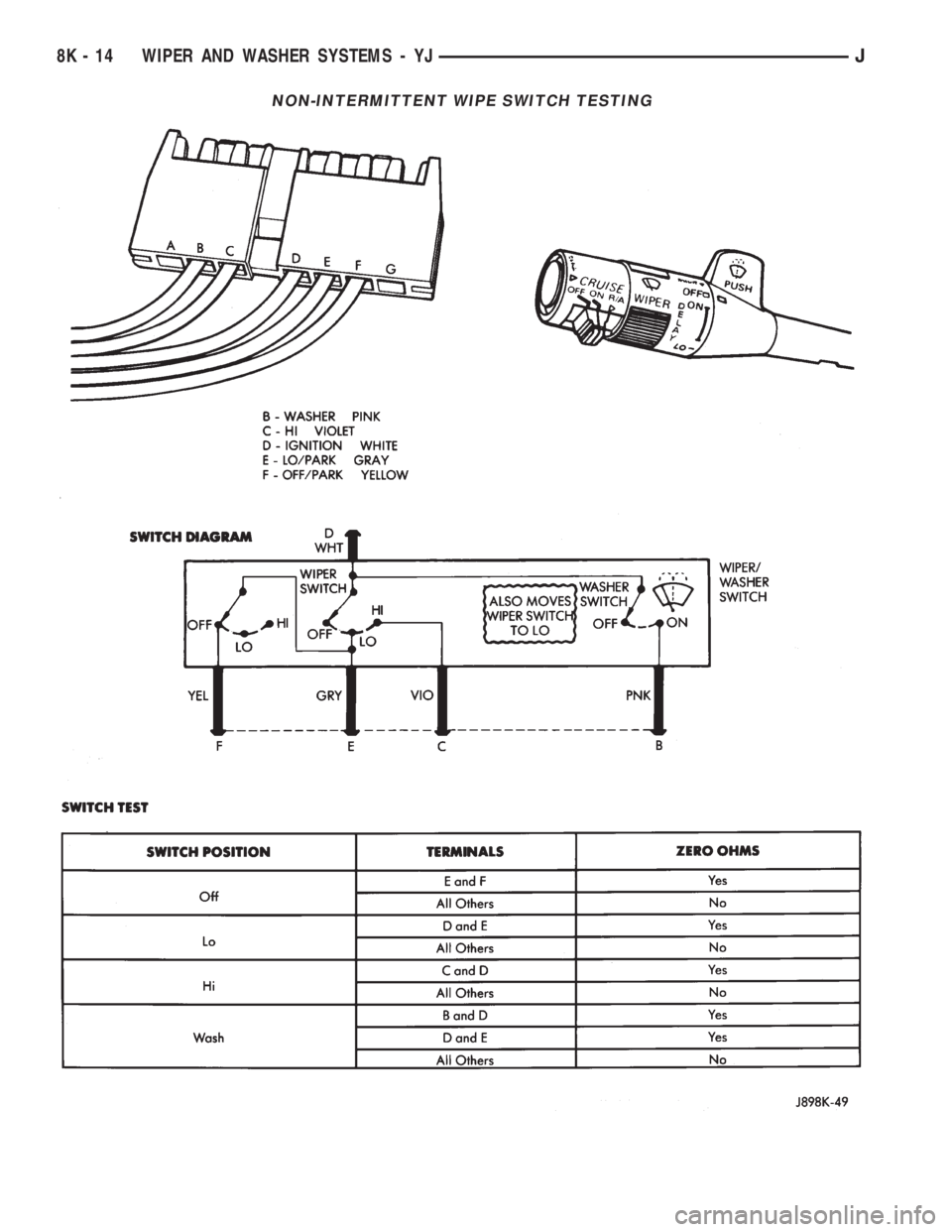
NON-INTERMITTENT WIPE SWITCH TESTING
8K - 14 WIPER AND WASHER SYSTEMS - YJJ
Page 449 of 2158
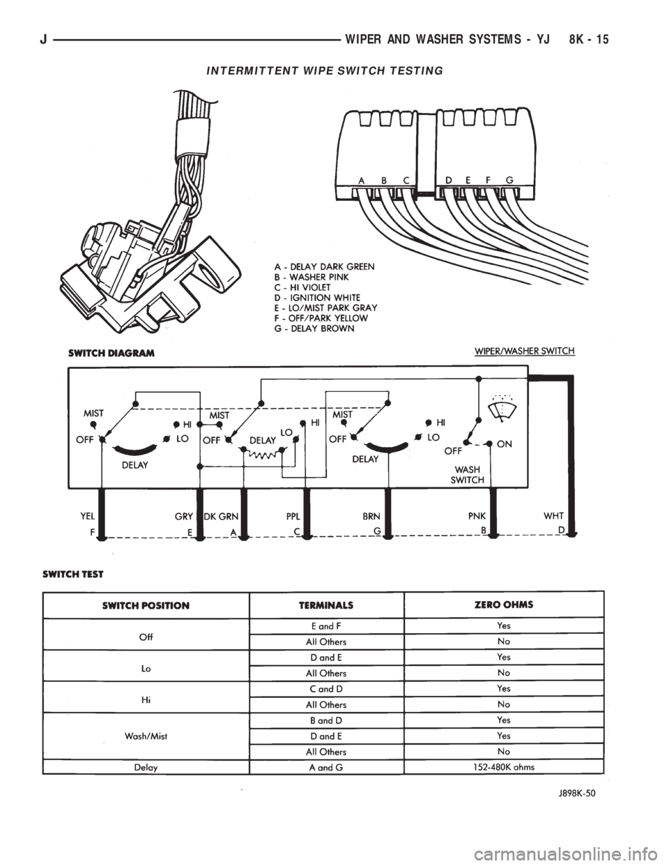
INTERMITTENT WIPE SWITCH TESTING
JWIPER AND WASHER SYSTEMS - YJ 8K - 15
Page 450 of 2158
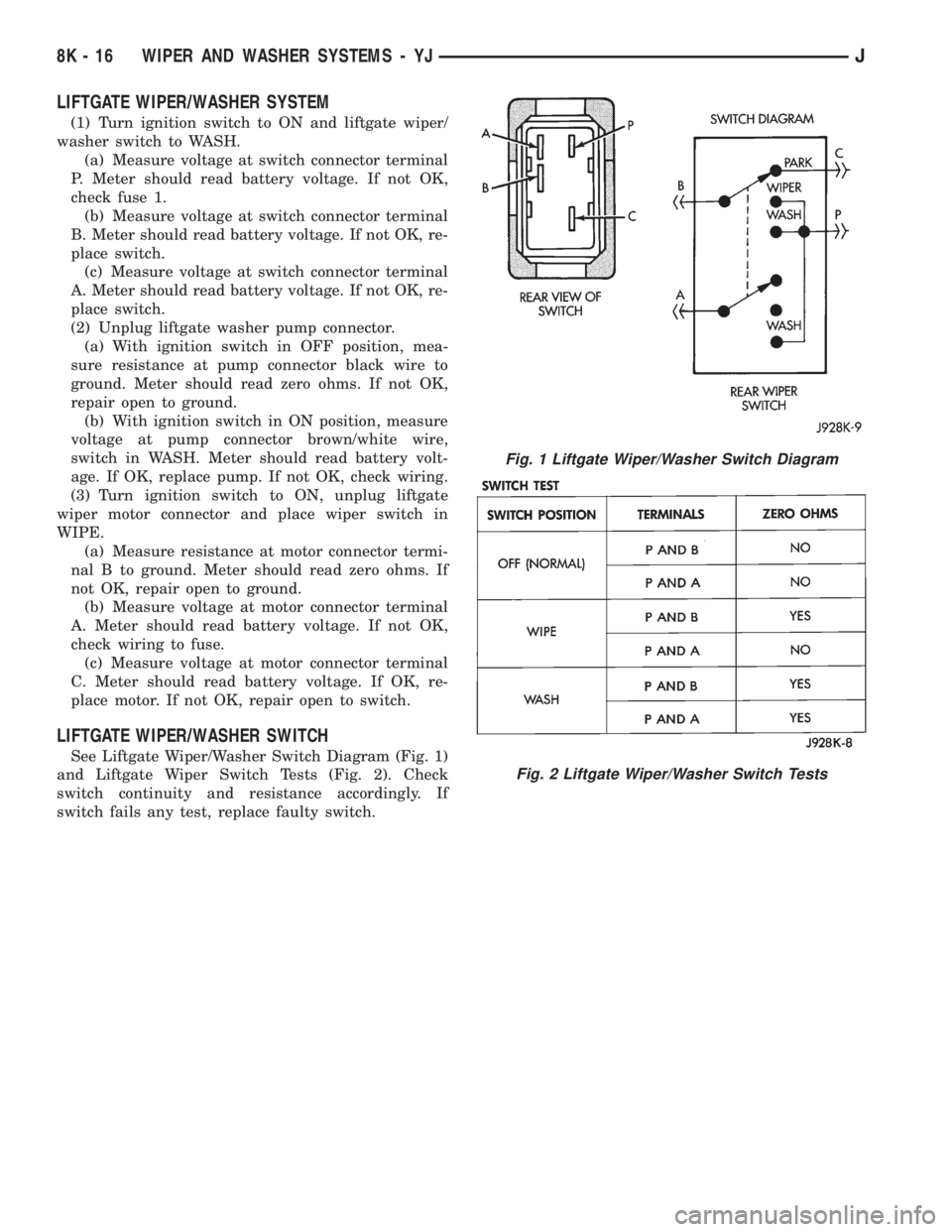
LIFTGATE WIPER/WASHER SYSTEM
(1) Turn ignition switch to ON and liftgate wiper/
washer switch to WASH.
(a) Measure voltage at switch connector terminal
P. Meter should read battery voltage. If not OK,
check fuse 1.
(b) Measure voltage at switch connector terminal
B. Meter should read battery voltage. If not OK, re-
place switch.
(c) Measure voltage at switch connector terminal
A. Meter should read battery voltage. If not OK, re-
place switch.
(2) Unplug liftgate washer pump connector.
(a) With ignition switch in OFF position, mea-
sure resistance at pump connector black wire to
ground. Meter should read zero ohms. If not OK,
repair open to ground.
(b) With ignition switch in ON position, measure
voltage at pump connector brown/white wire,
switch in WASH. Meter should read battery volt-
age. If OK, replace pump. If not OK, check wiring.
(3) Turn ignition switch to ON, unplug liftgate
wiper motor connector and place wiper switch in
WIPE.
(a) Measure resistance at motor connector termi-
nal B to ground. Meter should read zero ohms. If
not OK, repair open to ground.
(b) Measure voltage at motor connector terminal
A. Meter should read battery voltage. If not OK,
check wiring to fuse.
(c) Measure voltage at motor connector terminal
C. Meter should read battery voltage. If OK, re-
place motor. If not OK, repair open to switch.
LIFTGATE WIPER/WASHER SWITCH
See Liftgate Wiper/Washer Switch Diagram (Fig. 1)
and Liftgate Wiper Switch Tests (Fig. 2). Check
switch continuity and resistance accordingly. If
switch fails any test, replace faulty switch.
Fig. 1 Liftgate Wiper/Washer Switch Diagram
Fig. 2 Liftgate Wiper/Washer Switch Tests
8K - 16 WIPER AND WASHER SYSTEMS - YJJ