JEEP YJ 1995 Service And Repair Manual
Manufacturer: JEEP, Model Year: 1995, Model line: YJ, Model: JEEP YJ 1995Pages: 2158, PDF Size: 81.9 MB
Page 521 of 2158
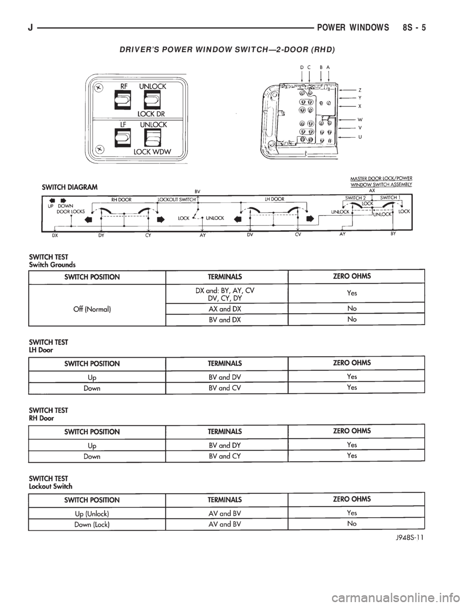
DRIVER'S POWER WINDOW SWITCHÐ2-DOOR (RHD)
JPOWER WINDOWS 8S - 5
Page 522 of 2158
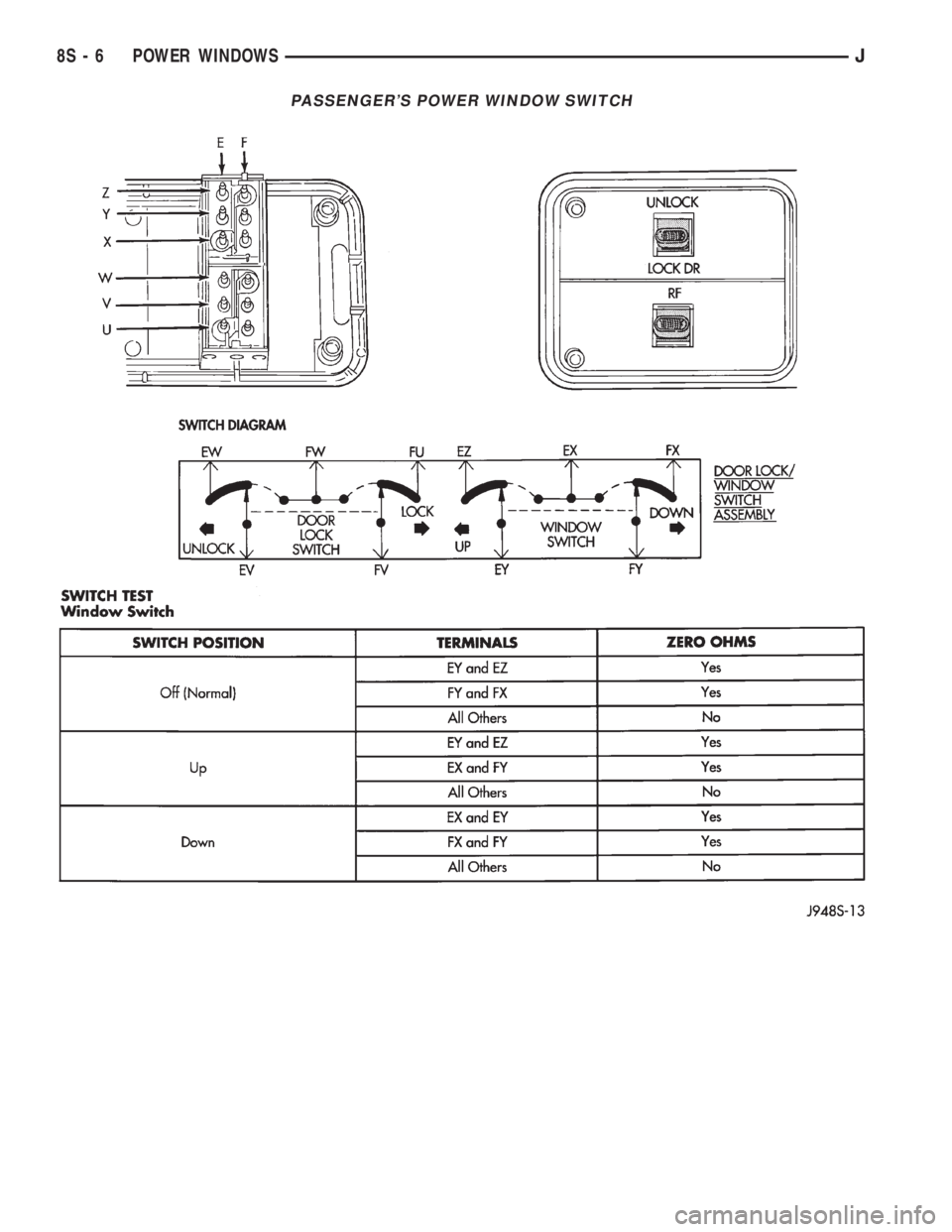
PASSENGER'S POWER WINDOW SWITCH
8S - 6 POWER WINDOWSJ
Page 523 of 2158
SERVICE PROCEDURES
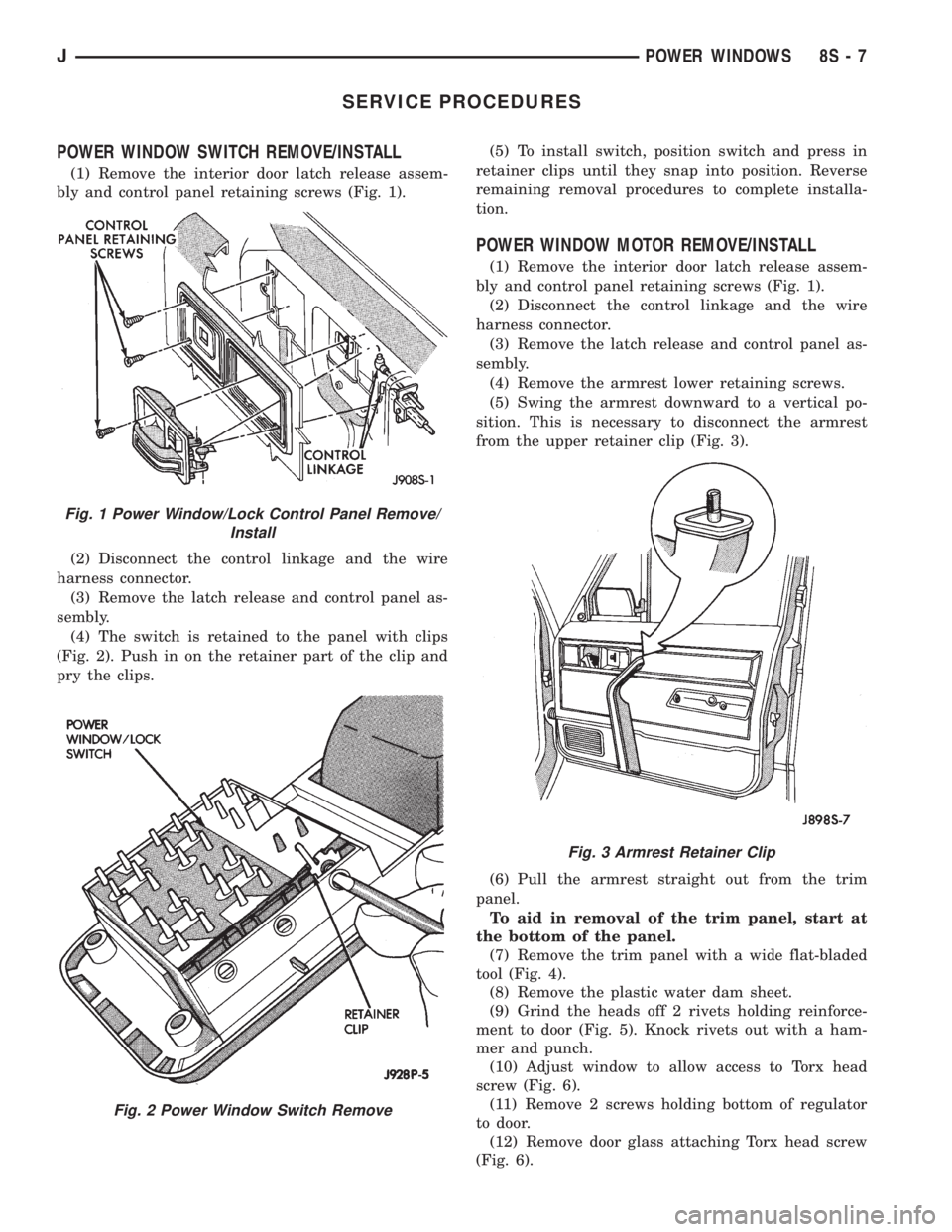
POWER WINDOW SWITCH REMOVE/INSTALL
(1) Remove the interior door latch release assem-
bly and control panel retaining screws (Fig. 1).
(2) Disconnect the control linkage and the wire
harness connector.
(3) Remove the latch release and control panel as-
sembly.
(4) The switch is retained to the panel with clips
(Fig. 2). Push in on the retainer part of the clip and
pry the clips.(5) To install switch, position switch and press in
retainer clips until they snap into position. Reverse
remaining removal procedures to complete installa-
tion.
POWER WINDOW MOTOR REMOVE/INSTALL
(1) Remove the interior door latch release assem-
bly and control panel retaining screws (Fig. 1).
(2) Disconnect the control linkage and the wire
harness connector.
(3) Remove the latch release and control panel as-
sembly.
(4) Remove the armrest lower retaining screws.
(5) Swing the armrest downward to a vertical po-
sition. This is necessary to disconnect the armrest
from the upper retainer clip (Fig. 3).
(6) Pull the armrest straight out from the trim
panel.
To aid in removal of the trim panel, start at
the bottom of the panel.
(7) Remove the trim panel with a wide flat-bladed
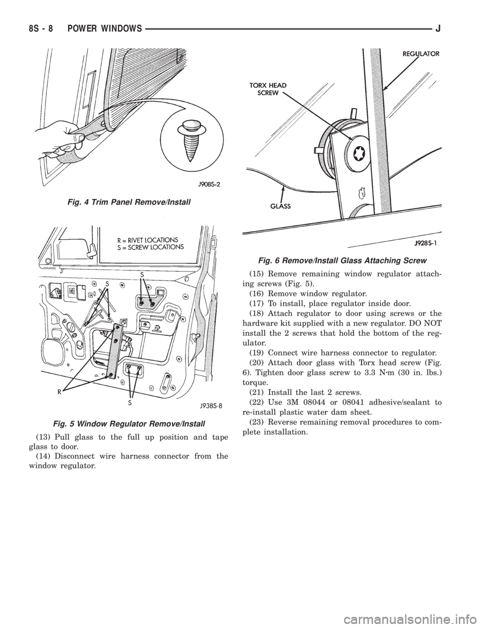
tool (Fig. 4).
(8) Remove the plastic water dam sheet.
(9) Grind the heads off 2 rivets holding reinforce-
ment to door (Fig. 5). Knock rivets out with a ham-
mer and punch.
(10) Adjust window to allow access to Torx head
screw (Fig. 6).
(11) Remove 2 screws holding bottom of regulator
to door.
(12) Remove door glass attaching Torx head screw
(Fig. 6).
Fig. 1 Power Window/Lock Control Panel Remove/
Install
Fig. 2 Power Window Switch Remove
Fig. 3 Armrest Retainer Clip
JPOWER WINDOWS 8S - 7
Page 524 of 2158
(13) Pull glass to the full up position and tape
glass to door.
(14) Disconnect wire harness connector from the
window regulator.(15) Remove remaining window regulator attach-
ing screws (Fig. 5).
(16) Remove window regulator.
(17) To install, place regulator inside door.
(18) Attach regulator to door using screws or the
hardware kit supplied with a new regulator. DO NOT
install the 2 screws that hold the bottom of the reg-
ulator.
(19) Connect wire harness connector to regulator.
(20) Attach door glass with Torx head screw (Fig.
6). Tighten door glass screw to 3.3 Nzm (30 in. lbs.)
torque.
(21) Install the last 2 screws.
(22) Use 3M 08044 or 08041 adhesive/sealant to
re-install plastic water dam sheet.
(23) Reverse remaining removal procedures to com-
plete installation.
Fig. 4 Trim Panel Remove/Install
Fig. 5 Window Regulator Remove/Install
Fig. 6 Remove/Install Glass Attaching Screw
8S - 8 POWER WINDOWSJ
Page 525 of 2158
POWER MIRRORS
CONTENTS
page page
DIAGNOSIS............................. 1
GENERAL INFORMATION.................. 1SERVICE PROCEDURES................... 4
GENERAL INFORMATION
Power outside rear view mirrors are an available
option on XJ (Cherokee) models. Following are gen-
eral descriptions of the major components in the
power mirror system. Refer to Group 8W - Wiring Di-
agrams for complete circuit descriptions and dia-
grams.
POWER MIRROR
The power mirrors are connected to battery feed at
all times. Each mirror head contains two electric mo-
tors, two drive mechanisms and the mirror glass.
One motor and drive controls mirror up-and-down
movement, and the other controls right-and-left
movement.
The mirror glass is the only serviced replacement
part for the power mirror assembly. If any other com-ponent of the mirror unit is faulty or damaged, the
entire assembly must be replaced.
POWER MIRROR SWITCH
Both the right and left mirror are controlled by a
multi-function switch located on the front of the cen-
ter console storage compartment, directly below the
armrest. The selector switch is moved right (right
mirror control), left (left mirror control), or center to
turn power mirrors off. Then one of four directional
control buttons is depressed to control movement of
the selected mirror up, down, right, or left. The
power mirror switch is serviced only as a complete
unit.
DIAGNOSIS
POWER MIRROR SYSTEM
(1) Check fuse 16 in Power Distribution Center
(PDC) and fuse 9 in fuseblock module. If OK, go to
next step. If not OK, replace fuse.
(2) Check for battery voltage at fuse 9 in fuseblock
module. If OK, go to next step. If not OK, repair cir-
cuit to fuse 16 in PDC.
(3) Remove power mirror switch from the center
console. See Power Mirror Switch Remove/Install.
(4) Disconnect wiring harness connector from
switch. Check for battery voltage at pink wire. If OK,
go to next step. If not OK, repair circuit to fuse 9 in
fuseblock module.
(5) Check for continuity between black wire in
switch harness connector and a good ground. There
should be continuity. If OK, go to next step. If not
OK, repair circuit to ground.
(6) Check switch continuity as shown in the Mirror
Switch Continuity charts. If OK, go to next step. If
not OK, replace switch.(7) See Power Mirror Switch illustration. Connect
a jumper wire from mirror switch connector cavity
for pin E to cavity for pin F. Now connect a second
jumper from connector cavity for pin G to each of the
following pin cavities: A, B, C, then D. In each case,
the selected mirror head should move. If OK, replace
switch. If not OK, go to next step.
(8) Remove door trim panel and unplug power mir-
ror connector inside door. Connect one jumper wire to
a good ground and a second jumper wire to a battery
feed. Connect other ends of jumpers to the mirror
side of connector in door (refer to Group 8W - Wiring
Diagrams for connector cavity identification). Mirror
head should move in each of the four directions. If
OK, repair wiring between mirror switch and door
connectors. If not OK, replace mirror.
JPOWER MIRRORS 8T - 1
Page 526 of 2158
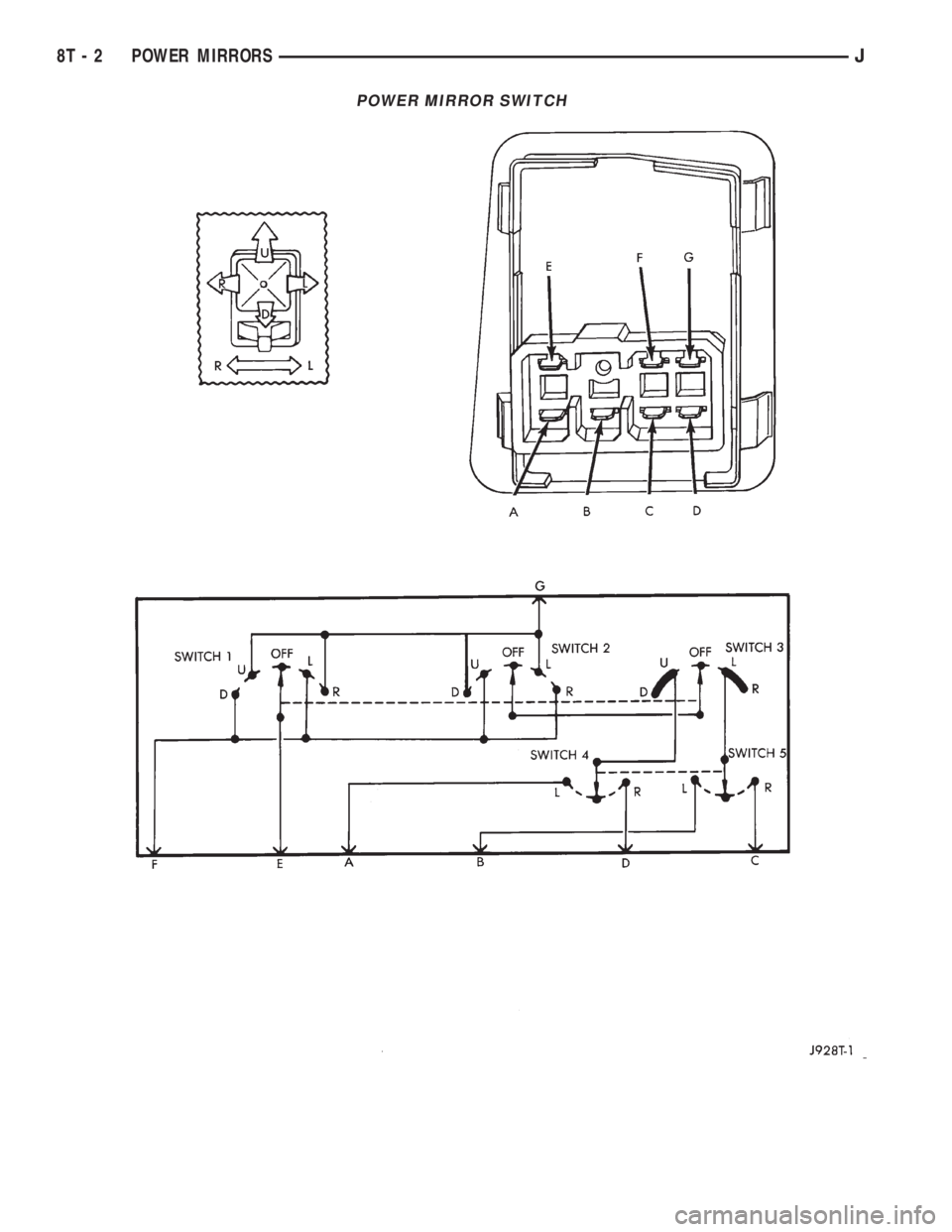
POWER MIRROR SWITCH
8T - 2 POWER MIRRORSJ
Page 527 of 2158
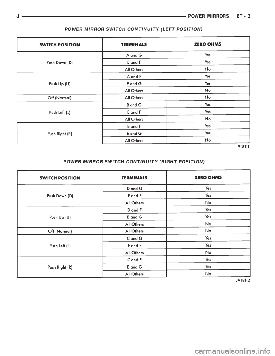
POWER MIRROR SWITCH CONTINUITY (LEFT POSITION)
POWER MIRROR SWITCH CONTINUITY (RIGHT POSITION)
JPOWER MIRRORS 8T - 3
Page 528 of 2158
SERVICE PROCEDURES
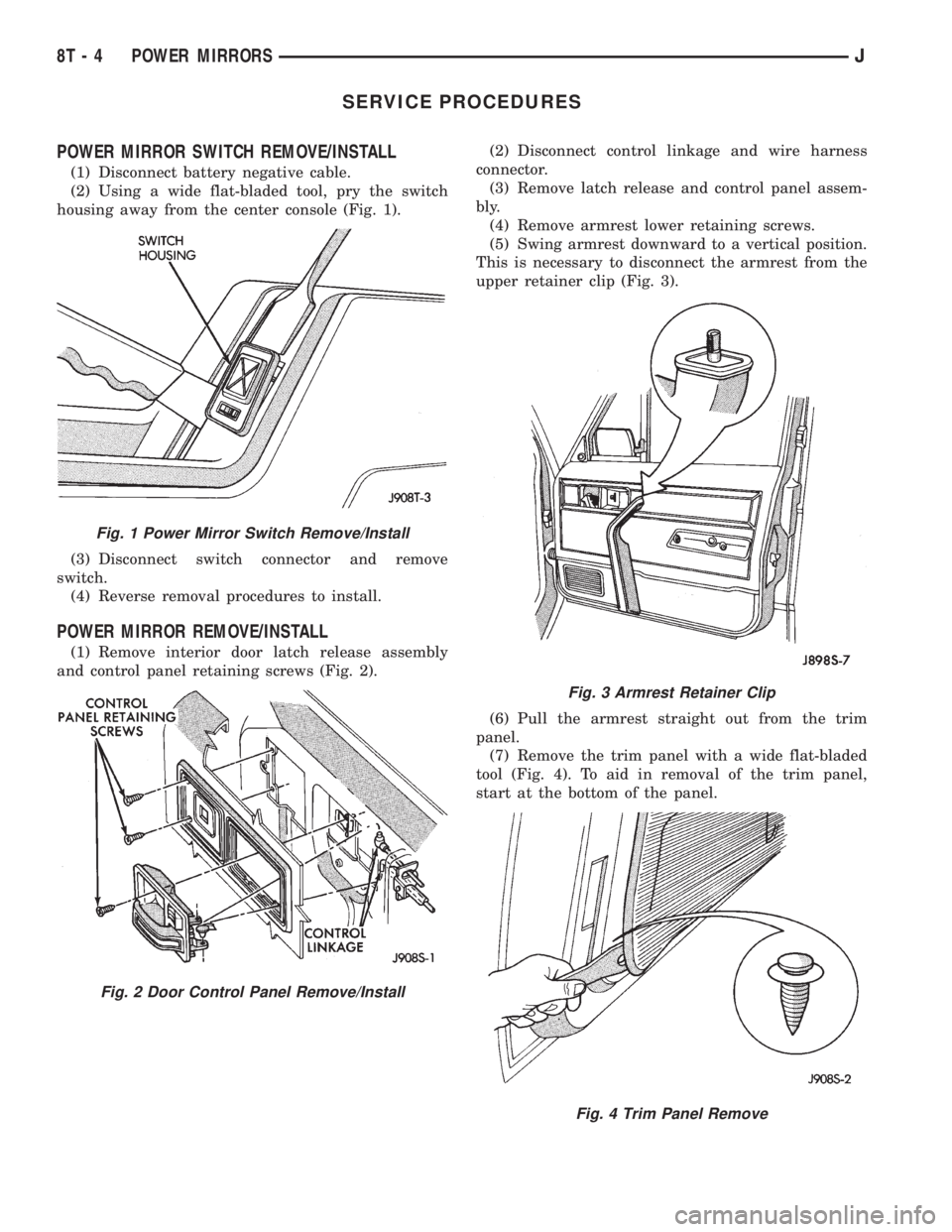
POWER MIRROR SWITCH REMOVE/INSTALL
(1) Disconnect battery negative cable.
(2) Using a wide flat-bladed tool, pry the switch
housing away from the center console (Fig. 1).
(3) Disconnect switch connector and remove
switch.
(4) Reverse removal procedures to install.
POWER MIRROR REMOVE/INSTALL
(1) Remove interior door latch release assembly
and control panel retaining screws (Fig. 2).(2) Disconnect control linkage and wire harness
connector.
(3) Remove latch release and control panel assem-
bly.
(4) Remove armrest lower retaining screws.
(5) Swing armrest downward to a vertical position.
This is necessary to disconnect the armrest from the
upper retainer clip (Fig. 3).
(6) Pull the armrest straight out from the trim
panel.
(7) Remove the trim panel with a wide flat-bladed
tool (Fig. 4). To aid in removal of the trim panel,
start at the bottom of the panel.
Fig. 1 Power Mirror Switch Remove/Install
Fig. 2 Door Control Panel Remove/Install
Fig. 3 Armrest Retainer Clip
Fig. 4 Trim Panel Remove
8T - 4 POWER MIRRORSJ
Page 529 of 2158
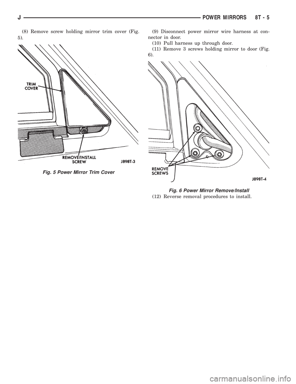
(8) Remove screw holding mirror trim cover (Fig.
5).(9) Disconnect power mirror wire harness at con-
nector in door.
(10) Pull harness up through door.
(11) Remove 3 screws holding mirror to door (Fig.
6).
(12) Reverse removal procedures to install.
Fig. 5 Power Mirror Trim Cover
Fig. 6 Power Mirror Remove/Install
JPOWER MIRRORS 8T - 5
Page 530 of 2158
