belt JEEP YJ 1995 Service And Workshop Manual
[x] Cancel search | Manufacturer: JEEP, Model Year: 1995, Model line: YJ, Model: JEEP YJ 1995Pages: 2158, PDF Size: 81.9 MB
Page 644 of 2158
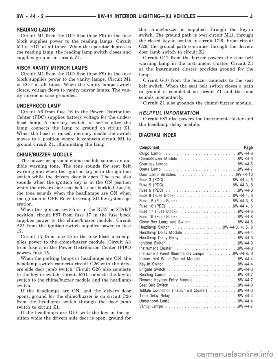
READING LAMPS
Circuit M1 from the IOD fuse (fuse F9) in the fuse
block supplies power to the reading lamps. Circuit
M1 is HOT at all times. When the operator depresses
the reading lamp, the reading lamp switch closes and
supplies ground on circuit Z1.
VISOR VANITY MIRROR LAMPS
Circuit M1 from the IOD fuse (fuse F9) in the fuse
block supplies power to the vanity lamps. Circuit M1
is HOT at all times. When the vanity lamps switch
closes, voltage flows to vanity mirror lamps. The van-
ity mirror is case grounded.
UNDERHOOD LAMP
Circuit A6 from fuse 16 in the Power Distribution
Center (PDC) supplies battery voltage for the under-
hood lamp. A mercury switch, in series after the
lamp, connects the lamp to ground on circuit Z1.
When the hood is raised, mercury inside the switch
moves to a position where it connects circuit M1 to
ground circuit Z1, illuminating the lamp.
CHIME/BUZZER MODULE
The buzzer or optional chime module sounds an au-
dible warning tone. The tone sounds for seat belt
warning and when the ignition key is in the ignition
switch while the drivers door is open. The tone also
sounds when the ignition key is in the ON position
while the drivers side seat belt is not buckled. Lastly,
the tone sounds when the headlamps are ON when
the ignition is OFF. Refer to Group 8U for system op-
eration.
When the ignition switch is in the RUN or START
position, circuit F87 from fuse 17 in the fuse block
supplies power to the chime/buzzer module. Circuit
A21 from the ignition switch supplies power to fuse
17.
Circuit L7 from fuse 15 in the fuse block also sup-
plies power to the chime/buzzer module. Circuit A3
from fuse 5 in the Power Distribution Center (PDC)
powers fuse 15.
When the parking lamps or headlamps are ON, the
headlamp switch connects circuit G26 with the driv-
ers side door jamb switch. Circuit G26 also connects
to the key-in switch. Circuit M11 connects the key-in
switch to the chime/buzzer module and the headlamp
switch.
If the headlamps are ON, and the drivers door
opens, ground for the chime/buzzer is on circuit C26
from the headlamp switch through the door jamb
switch to circuit Z1.
If the headlamps are OFF with the key in the ig-
nition while the drivers side door is open, ground forthe chime/buzzer is supplied through the key-in
switch. The ground path is over circuit M11, through
the closed key-in switch to circuit C26. From circuit
C26, the ground path continues through the drivers
door jamb switch to circuit Z1.
Circuit G11 from the buzzer powers the seat belt
warning lamp in the instrument cluster. Circuit Z1
at the instrument cluster provides ground for the
lamp.
Circuit G10 from the buzzer connects to the seat
belt switch. When the seat belt switch closes a path
to ground is completed on circuit Z1 and the tone
sounds momentarily.
Circuit Z1 also grounds the chime\buzzer module.
HELPFUL INFORMATION
Circuit F87 also powers the instrument cluster and
the headlamp delay module.
DIAGRAM INDEX
Component Page
Cargo Lamp............................8W-44-6
Chime/Buzzer Module......................8W-44-3
Courtesy Lamps.........................8W-44-5
Dome Lamp............................8W-44-7
Door Jamb Switches.....................8W-44-10
Fuse 3 (PDC).........................8W-44-4, 6
Fuse 5 (PDC).........................8W-44-3, 8
Fuse 6 (PDC)...........................8W-44-3
Fuse 9 (Fuse Block).....................8W-44-4, 6
Fuse 15 (Fuse Block)....................8W-44-3, 8
Fuse 16 (PDC)........................8W-44-4, 6
Fuse 17 (Fuse Block)......................8W-44-3
Fuse 19 (Fuse Block)......................8W-44-8
Glove Box Lamp and Switch.................8W-44-5
Headlamp Switch...................8W-44-3, 4, 5, 8
Headlamp Delay Module....................8W-44-4
Headlamp Delay Relay.....................8W-44-3
Ignition Switch..........................8W-44-3
Instrument Cluster........................8W-44-3
Instrument Panel Illumination Lamps..........8W-44-8, 9
Intermittent Wiper Control Module.............8W-44-4
Key-In Switch...........................8W-44-4
Liftgate Switch..........................8W-44-6
Reading Lamps..........................8W-44-7
Remote Keyless Entry Module................8W-44-7
Seat Belt Switch.........................8W-44-3
Telltale Connector (Instrument Cluster)...........8W-44-3
Time Delay Relay........................8W-44-4
Underhood Lamp.........................8W-44-4
Vanity Lamps...........................8W-44-7
8W - 44 - 2 8W-44 INTERIOR LIGHTINGÐXJ VEHICLESJ
Page 890 of 2158
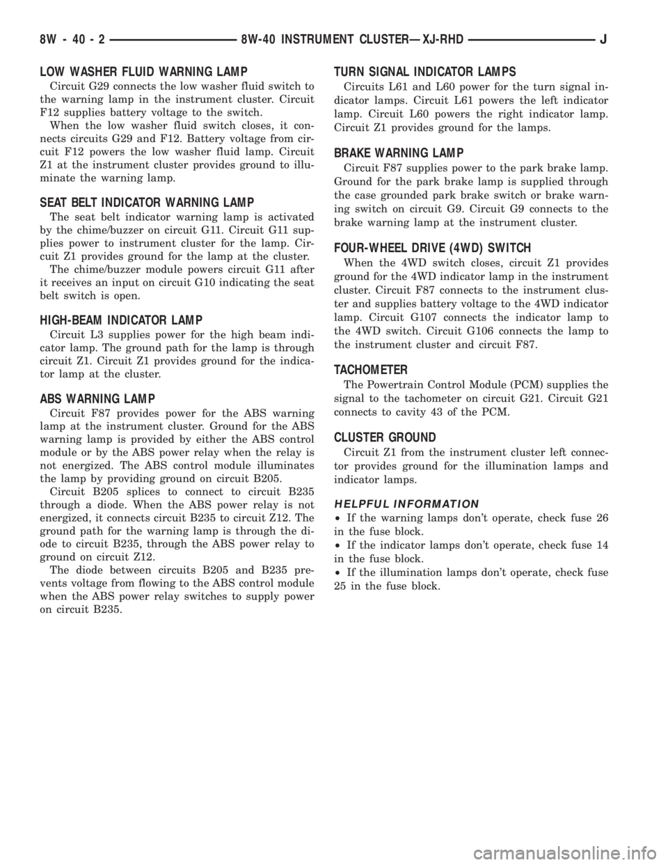
LOW WASHER FLUID WARNING LAMP
Circuit G29 connects the low washer fluid switch to
the warning lamp in the instrument cluster. Circuit
F12 supplies battery voltage to the switch.
When the low washer fluid switch closes, it con-
nects circuits G29 and F12. Battery voltage from cir-
cuit F12 powers the low washer fluid lamp. Circuit
Z1 at the instrument cluster provides ground to illu-
minate the warning lamp.
SEAT BELT INDICATOR WARNING LAMP
The seat belt indicator warning lamp is activated
by the chime/buzzer on circuit G11. Circuit G11 sup-
plies power to instrument cluster for the lamp. Cir-
cuit Z1 provides ground for the lamp at the cluster.
The chime/buzzer module powers circuit G11 after
it receives an input on circuit G10 indicating the seat
belt switch is open.
HIGH-BEAM INDICATOR LAMP
Circuit L3 supplies power for the high beam indi-
cator lamp. The ground path for the lamp is through
circuit Z1. Circuit Z1 provides ground for the indica-
tor lamp at the cluster.
ABS WARNING LAMP
Circuit F87 provides power for the ABS warning
lamp at the instrument cluster. Ground for the ABS
warning lamp is provided by either the ABS control
module or by the ABS power relay when the relay is
not energized. The ABS control module illuminates
the lamp by providing ground on circuit B205.
Circuit B205 splices to connect to circuit B235
through a diode. When the ABS power relay is not
energized, it connects circuit B235 to circuit Z12. The
ground path for the warning lamp is through the di-
ode to circuit B235, through the ABS power relay to
ground on circuit Z12.
The diode between circuits B205 and B235 pre-
vents voltage from flowing to the ABS control module
when the ABS power relay switches to supply power
on circuit B235.
TURN SIGNAL INDICATOR LAMPS
Circuits L61 and L60 power for the turn signal in-
dicator lamps. Circuit L61 powers the left indicator
lamp. Circuit L60 powers the right indicator lamp.
Circuit Z1 provides ground for the lamps.
BRAKE WARNING LAMP
Circuit F87 supplies power to the park brake lamp.
Ground for the park brake lamp is supplied through
the case grounded park brake switch or brake warn-
ing switch on circuit G9. Circuit G9 connects to the
brake warning lamp at the instrument cluster.
FOUR-WHEEL DRIVE (4WD) SWITCH
When the 4WD switch closes, circuit Z1 provides
ground for the 4WD indicator lamp in the instrument
cluster. Circuit F87 connects to the instrument clus-
ter and supplies battery voltage to the 4WD indicator
lamp. Circuit G107 connects the indicator lamp to
the 4WD switch. Circuit G106 connects the lamp to
the instrument cluster and circuit F87.
TACHOMETER
The Powertrain Control Module (PCM) supplies the
signal to the tachometer on circuit G21. Circuit G21
connects to cavity 43 of the PCM.
CLUSTER GROUND
Circuit Z1 from the instrument cluster left connec-
tor provides ground for the illumination lamps and
indicator lamps.
HELPFUL INFORMATION
²If the warning lamps don't operate, check fuse 26
in the fuse block.
²If the indicator lamps don't operate, check fuse 14
in the fuse block.
²If the illumination lamps don't operate, check fuse
25 in the fuse block.
8W - 40 - 2 8W-40 INSTRUMENT CLUSTERÐXJ-RHDJ
Page 914 of 2158
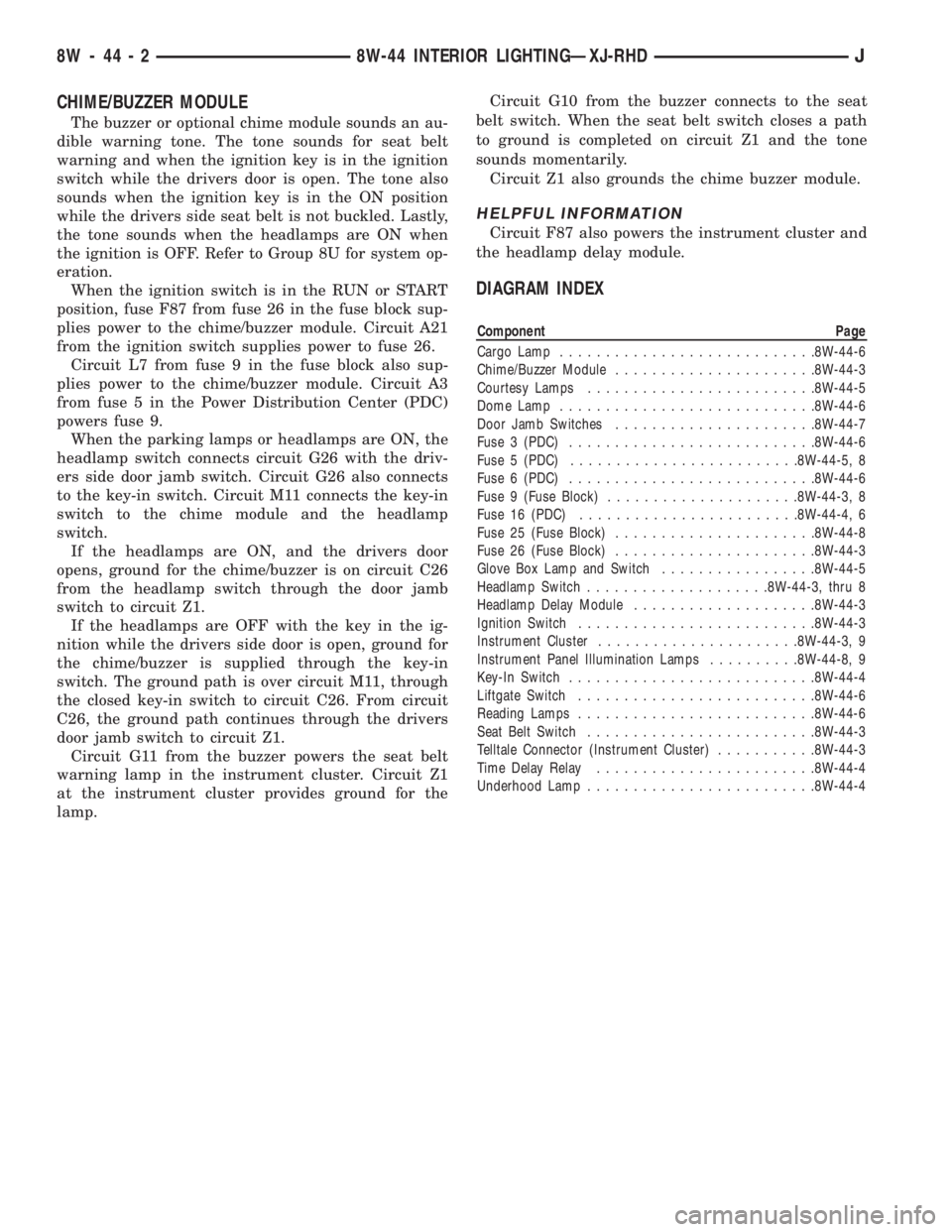
CHIME/BUZZER MODULE
The buzzer or optional chime module sounds an au-
dible warning tone. The tone sounds for seat belt
warning and when the ignition key is in the ignition
switch while the drivers door is open. The tone also
sounds when the ignition key is in the ON position
while the drivers side seat belt is not buckled. Lastly,
the tone sounds when the headlamps are ON when
the ignition is OFF. Refer to Group 8U for system op-
eration.
When the ignition switch is in the RUN or START
position, fuse F87 from fuse 26 in the fuse block sup-
plies power to the chime/buzzer module. Circuit A21
from the ignition switch supplies power to fuse 26.
Circuit L7 from fuse 9 in the fuse block also sup-
plies power to the chime/buzzer module. Circuit A3
from fuse 5 in the Power Distribution Center (PDC)
powers fuse 9.
When the parking lamps or headlamps are ON, the
headlamp switch connects circuit G26 with the driv-
ers side door jamb switch. Circuit G26 also connects
to the key-in switch. Circuit M11 connects the key-in
switch to the chime module and the headlamp
switch.
If the headlamps are ON, and the drivers door
opens, ground for the chime/buzzer is on circuit C26
from the headlamp switch through the door jamb
switch to circuit Z1.
If the headlamps are OFF with the key in the ig-
nition while the drivers side door is open, ground for
the chime/buzzer is supplied through the key-in
switch. The ground path is over circuit M11, through
the closed key-in switch to circuit C26. From circuit
C26, the ground path continues through the drivers
door jamb switch to circuit Z1.
Circuit G11 from the buzzer powers the seat belt
warning lamp in the instrument cluster. Circuit Z1
at the instrument cluster provides ground for the
lamp.Circuit G10 from the buzzer connects to the seat
belt switch. When the seat belt switch closes a path
to ground is completed on circuit Z1 and the tone
sounds momentarily.
Circuit Z1 also grounds the chime buzzer module.
HELPFUL INFORMATION
Circuit F87 also powers the instrument cluster and
the headlamp delay module.
DIAGRAM INDEX
Component Page
Cargo Lamp............................8W-44-6
Chime/Buzzer Module......................8W-44-3
Courtesy Lamps.........................8W-44-5
Dome Lamp............................8W-44-6
Door Jamb Switches......................8W-44-7
Fuse 3 (PDC)...........................8W-44-6
Fuse 5 (PDC).........................8W-44-5, 8
Fuse 6 (PDC)...........................8W-44-6
Fuse 9 (Fuse Block).....................8W-44-3, 8
Fuse 16 (PDC)........................8W-44-4, 6
Fuse 25 (Fuse Block)......................8W-44-8
Fuse 26 (Fuse Block)......................8W-44-3
Glove Box Lamp and Switch.................8W-44-5
Headlamp Switch....................8W-44-3, thru 8
Headlamp Delay Module....................8W-44-3
Ignition Switch..........................8W-44-3
Instrument Cluster......................8W-44-3, 9
Instrument Panel Illumination Lamps..........8W-44-8, 9
Key-In Switch...........................8W-44-4
Liftgate Switch..........................8W-44-6
Reading Lamps..........................8W-44-6
Seat Belt Switch.........................8W-44-3
Telltale Connector (Instrument Cluster)...........8W-44-3
Time Delay Relay........................8W-44-4
Underhood Lamp.........................8W-44-4
8W - 44 - 2 8W-44 INTERIOR LIGHTINGÐXJ-RHDJ
Page 1068 of 2158
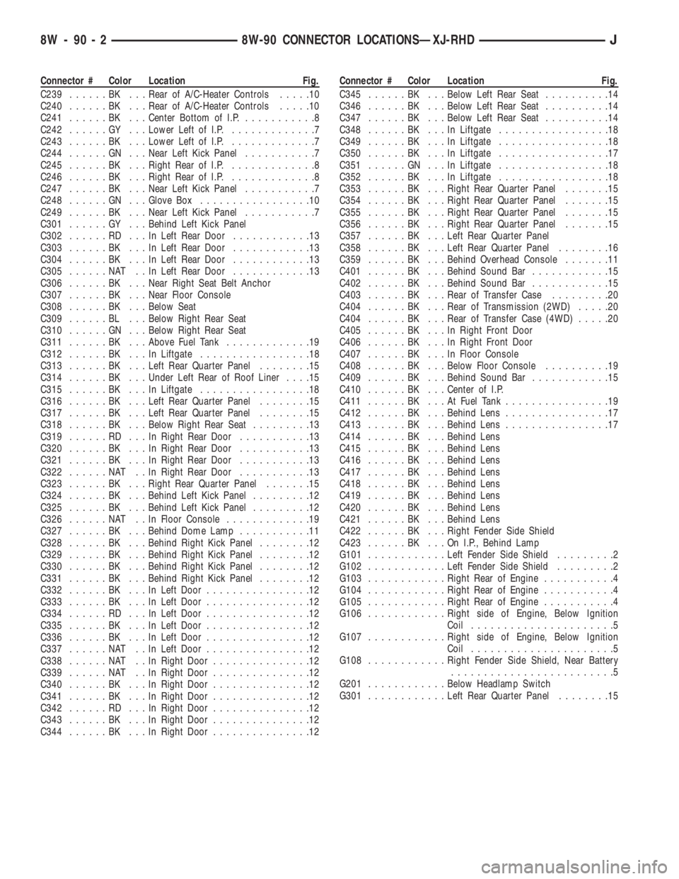
Connector # Color Location Fig.
C239......BK ...Rear of A/C-Heater Controls.....10
C240......BK ...Rear of A/C-Heater Controls.....10
C241......BK ...Center Bottom of I.P............8
C242......GY ...Lower Left of I.P..............7
C243......BK ...Lower Left of I.P..............7
C244......GN ...Near Left Kick Panel...........7
C245......BK ...Right Rear of I.P..............8
C246......BK ...Right Rear of I.P..............8
C247......BK ...Near Left Kick Panel...........7
C248......GN ...Glove Box.................10
C249......BK ...Near Left Kick Panel...........7
C301......GY ...Behind Left Kick Panel
C302......RD ...InLeft Rear Door............13
C303......BK ...InLeft Rear Door............13
C304......BK ...InLeft Rear Door............13
C305......NAT ..InLeft Rear Door............13
C306......BK ...Near Right Seat Belt Anchor
C307......BK ...Near Floor Console
C308......BK ...Below Seat
C309......BL ...Below Right Rear Seat
C310......GN ...Below Right Rear Seat
C311......BK ...Above Fuel Tank.............19
C312......BK ...InLiftgate.................18
C313......BK ...Left Rear Quarter Panel........15
C314......BK ...Under Left Rear of Roof Liner....15
C315......BK ...InLiftgate.................18
C316......BK ...Left Rear Quarter Panel........15
C317......BK ...Left Rear Quarter Panel........15
C318......BK ...Below Right Rear Seat.........13
C319......RD ...InRight Rear Door...........13
C320......BK ...InRight Rear Door...........13
C321......BK ...InRight Rear Door...........13
C322......NAT ..InRight Rear Door...........13
C323......BK ...Right Rear Quarter Panel.......15
C324......BK ...Behind Left Kick Panel.........12
C325......BK ...Behind Left Kick Panel.........12
C326......NAT ..InFloor Console.............19
C327......BK ...Behind Dome Lamp...........11
C328......BK ...Behind Right Kick Panel........12
C329......BK ...Behind Right Kick Panel........12
C330......BK ...Behind Right Kick Panel........12
C331......BK ...Behind Right Kick Panel........12
C332......BK ...InLeft Door................12
C333......BK ...InLeft Door................12
C334......RD ...InLeft Door................12
C335......BK ...InLeft Door................12
C336......BK ...InLeft Door................12
C337......NAT ..InLeft Door................12
C338......NAT ..InRight Door...............12
C339......NAT ..InRight Door...............12
C340......BK ...InRight Door...............12
C341......BK ...InRight Door...............12
C342......RD ...InRight Door...............12
C343......BK ...InRight Door...............12
C344......BK ...InRight Door...............12Connector # Color Location Fig.
C345......BK ...Below Left Rear Seat..........14
C346......BK ...Below Left Rear Seat..........14
C347......BK ...Below Left Rear Seat..........14
C348......BK ...InLiftgate.................18
C349......BK ...InLiftgate.................18
C350......BK ...InLiftgate.................17
C351......GN ...InLiftgate.................18
C352......BK ...InLiftgate.................18
C353......BK ...Right Rear Quarter Panel.......15
C354......BK ...Right Rear Quarter Panel.......15
C355......BK ...Right Rear Quarter Panel.......15
C356......BK ...Right Rear Quarter Panel.......15
C357......BK ...Left Rear Quarter Panel
C358......BK ...Left Rear Quarter Panel........16
C359......BK ...Behind Overhead Console.......11
C401......BK ...Behind Sound Bar............15
C402......BK ...Behind Sound Bar............15
C403......BK ...Rear of Transfer Case.........20
C404......BK ...Rear of Transmission (2WD).....20
C404......BK ...Rear of Transfer Case (4WD).....20
C405......BK ...InRight Front Door
C406......BK ...InRight Front Door
C407......BK ...InFloor Console
C408......BK ...Below Floor Console..........19
C409......BK ...Behind Sound Bar............15
C410......BK ...Center of I.P.
C411......BK ...AtFuel Tank................19
C412......BK ...Behind Lens................17
C413......BK ...Behind Lens................17
C414......BK ...Behind Lens
C415......BK ...Behind Lens
C416......BK ...Behind Lens
C417......BK ...Behind Lens
C418......BK ...Behind Lens
C419......BK ...Behind Lens
C420......BK ...Behind Lens
C421......BK ...Behind Lens
C422......BK ...Right Fender Side Shield
C423......BK ...OnI.P.,Behind Lamp
G101............Left Fender Side Shield.........2
G102............Left Fender Side Shield.........2
G103............Right Rear of Engine...........4
G104............Right Rear of Engine...........4
G105............Right Rear of Engine...........4
G106............Right side of Engine, Below Ignition
Coil......................5
G107............Right side of Engine, Below Ignition
Coil......................5
G108............Right Fender Side Shield, Near Battery
.........................5
G201............Below Headlamp Switch
G301............Left Rear Quarter Panel........15
8W - 90 - 2 8W-90 CONNECTOR LOCATIONSÐXJ-RHDJ
Page 1174 of 2158
INTERIOR LIGHTING
INDEX
page page
Accessory Lamp and Heater Control Panel Lamp . . 1
Combination Buzzer........................ 1
Courtesy Lamps and Dome Lamps............. 1
Diagram Index............................ 2General Information........................ 1
Transmission Range Lamp................... 1
Underhood Lamp.......................... 1
GENERAL INFORMATION
Circuit M1 supplies power to the underhood lamp,
dome lamp, right courtesy lamp and left courtesy
lamp. Fuse 12 in the Power Distribution Center
(PDC) protects circuit M1. Circuit A4 from fuse 8 in
the PDC supplies voltage to fuse 12 and circuit M1.
Fuse 12 is referred to as the Ignition Off Draw (IOD)
fuse.
COURTESY LAMPS AND DOME LAMPS
Circuit M1 supplies battery voltage to the dome
lamps and the right and left courtesy lamps. Circuit
M2 provides ground for the lamps through either the
case grounded door jamb switches or through the
dimmer switch to circuit Z1.
In the ON position, the dimmer switch connects
circuit M2 to ground on circuit Z1. When a door
opens, the case grounded door jamb switch closes and
provides ground for the lamps on circuit M2.
HELPFUL INFORMATION
²Circuit M1 also supplies voltage for radio memory,
underhood lamp and the ABS data link connector.
UNDERHOOD LAMP
Circuit M1 supplies battery voltage for the under-
hood lamp. A mercury switch in series after the lamp
connects the lamp to ground on circuit Z1. When the
hood is raised, mercury inside the switch moves to a
position where it connects circuit M1 to circuit Z1, il-
luminating the lamp. The underhood lamp is wired
in parallel with other components on circuit M1.
ACCESSORY LAMP AND HEATER CONTROL PANEL
LAMP
Circuit E1 from the dimmer switch supplies bat-
tery voltage to fuse 10 in the fuse block when the
dimmer switch is in the LOW or ON position. Fuse
10 protects circuit E2 which supplies power to the
heater control panel lamp and the accessory lamp.
Circuit Z1 provides ground for each lamp.
TRANSMISSION RANGE LAMP
Circuit E1 from the dimmer switch supplies bat-
tery voltage to fuse 10 in the fuse block when thedimmer switch is in the LOW or ON positions. Fuse
10 protects circuit E2 which supplies power to the
transmission range lamp. The lamp is case grounded.
COMBINATION BUZZER
The combination buzzer module sounds an audible
warning tone. The tone sounds for seat belt warning
and when the key is in the ignition switch while the
drivers door is open. The tone also sounds when the
ignition switch is in the ON position while the driv-
ers side seat belt is not buckled. Refer to Group 8U
for buzzer operation.
Fuses 3 and 9 in the fuse block protect the combi-
nation buzzer. Fuse 3 powers circuit F32 which con-
nects to the buzzer. Circuit A6 from fuse 3 in the
Power Distribution Center (PDC) supplies power to
the fuse block for circuit F32.
Circuit G5 from fuse 9 also provides voltage to the
combination buzzer when the ignition switch is in
the START or RUN position. The ignition switch con-
nects circuit A1 from fuse 4 in the PDC to circuit
A21. Circuit A21 connects to the fuse block.
When the key-in switch closes, it connects circuit
G26 to circuit G16. Circuit G16 connects to the driv-
ers side door jamb switch. When the drivers side door
is open and the key-in switch is closed, the case
grounded door jamb switch closes and supplies
ground for the buzzer. Circuit G26 from the combina-
tion buzzer connects to the key-in switch.
Circuit G13 form the buzzer powers the seat belt
warning lamp in the instrument cluster. Circuit Z1
at the instrument cluster provides ground for the
lamp.
Circuit G10 from the buzzer connects to the seat
belt switch. When the seat belt is unlatched, the seat
belt switch closes providing ground on circuit Z1.
Circuit Z1 also grounds the combination buzzer
module.
HELPFUL INFORMATION
²Circuit F32 also powers the stop lamp switch.
²Circuit G5 also provides power for the instrument
cluster gauges and warning lamps, heated rear win-
dow relay and A/C compressor clutch relay. On Cana-
J8W-44 INTERIOR LIGHTINGÐYJ VEHICLES 8W - 44 - 1
Page 1175 of 2158
dian vehicles, circuit G5 also powers the Daytime
Running Lamps (DRL) module.DIAGRAM INDEX
Component Page
Combination Buzzer.......................8W-44-5
Courtesy Lamps.........................8W-44-4
Dome Lamps...........................8W-44-4
Door Jamb Switches......................8W-44-4
Fuse 3 (Fuse Block).......................8W-44-5
Fuse 3 (PDC).........................8W-44-3, 5
Fuse 4 (PDC)...........................8W-44-5
Fuse 8 (Fuse Block).......................8W-44-3
Fuse 8 (PDC)...........................8W-44-4
Fuse 9 (Fuse Block).......................8W-44-5
Fuse 10 (Fuse Block)......................8W-44-3
Fuse 12 (PDC)..........................8W-44-4
Headlamp Switch.........................8W-44-3
Ignition Switch..........................8W-44-5
Illumination Lamps.......................8W-44-3
Key-In Switch...........................8W-44-5
Panel Lamp Dimmer Switch................8W-44-3, 4
Seat Belt Switch.........................8W-44-5
Underhood Lamp.........................8W-44-4
8W - 44 - 2 8W-44 INTERIOR LIGHTINGÐYJ VEHICLESJ
Page 1281 of 2158
minutes). The use of a locating dowel is recom-
mended during assembly to prevent smearing the
material off location.
Mopar Gasket Maker should be applied sparingly
to one gasket surface. The sealant diameter should
be 1.00 mm (0.04 inch) or less. Be certain the mate-
rial surrounds each mounting hole. Excess material
can easily be wiped off. Components should be
torqued in place within 15 minutes. The use of a lo-
cating dowel is recommended during assembly to pre-
vent smearing the material off location.
ENGINE PERFORMANCE
To provide best vehicle performance and lowest ve-
hicle emissions, it is most important that the tune-up
be done accurately. Use the specifications listed on
the Vehicle Emission Control Information label found
on the engine compartment hood.
(1) Test battery specific gravity. Add water, if nec-
essary. Clean and tighten battery connections.
(2) Test cranking amperage draw (refer to Group
8B, Battery/Starter Service for the proper proce-
dures).
(3) Tighten the intake manifold bolts (refer to
Group 11, Exhaust System and Intake Manifold for
the proper specifications).
(4) Perform cylinder compression test:
(a) Check engine oil level and add oil, if neces-
sary.
(b) Drive the vehicle until engine reaches normal
operating temperature.
(c) Select a route free from traffic and other
forms of congestion, observe all traffic laws and
briskly accelerate through the gears several times.
The higher engine speed may help clean out valve
seat deposits which can prevent accurate compres-
sion readings.
CAUTION: DO NOT overspeed the engine.
(d) Remove all spark plugs from engine. As spark
plugs are being removed, check electrodes for ab-
normal firing indicatorsÐfouled, hot, oily, etc.
Record cylinder number of spark plug for future
reference.
(e) Disconnect coil wire from distributor and se-
cure to good ground to prevent a spark from start-
ing a fire.
(f) Be sure throttle blades are fully open during
the compression check.
(g) Insert compression gage adaptor into the
No.1 spark plug hole. Crank engine until maximum
pressure is reached on gauge. Record this pressure
as No.1 cylinder pressure.
(h) Repeat Step 4g for all remaining cylinders.
(i) Compression should not be less than 689 kPa
(100 psi) and not vary more than 172 kPa (25 psi)
from cylinder to cylinder.(j) If cylinder(s) have abnormally low compres-
sion pressures, repeat steps 4a through 4h.
(k) If the same cylinder(s) repeat an abnormally
low reading, it could indicate the existence of a
problem in the cylinder.
The recommended compression pressures are
to be used only as a guide to diagnosing engine
problems. An engine should NOT be disassem-
bled to determine the cause of low compression
unless some malfunction is present.
(5) Clean or replace spark plugs as necessary. Ad-
just gap (refer to Group 8D, Ignition System for gap
adjustment and torque).
(6) Test resistance of spark plug cables (refer to
Group 8D, Ignition System).
(7) Inspect the primary wire. Test coil output volt-
age, primary and secondary resistance. Replace parts
as necessary (refer to Group 8D, Ignition System and
make necessary adjustment).
(8) Perform a combustion analysis.
(9) Test fuel pump for pressure (refer to Group 14,
Fuel System for the proper specifications).
(10) Inspect air filter element (refer to Group 0,
Lubrication and Maintenance for the proper proce-
dure).
(11) Inspect crankcase ventilation system (refer to
Group 0, Lubrication and Maintenance for the proper
procedure).
(12) For emission controls refer to Group 25, Emis-
sion Controls System for service procedures.
(13) Inspect and adjust accessory belt drives (refer
to Group 7, Cooling System for the proper adjust-
ments).
(14) Road test vehicle as a final test.
HONING CYLINDER BORES
Before honing, stuff plenty of clean shop towels un-
der the bores and over the crankshaft to keep abra-
sive materials from entering the crankshaft area.
(1) Used carefully, the Cylinder Bore Sizing Hone
C-823 equipped with 220 grit stones, is the best tool
for this job. In addition to deglazing, it will reduce
taper and out-of-round as well as removing light
scuffing, scoring or scratches. Usually a few strokes
will clean up a bore and maintain the required lim-
its.
CAUTION: DO NOT use rigid type hones to remove
cylinder wall glaze.
(2) Deglazing of the cylinder walls may be done if
the cylinder bore is straight and round. Use a cylin-
der surfacing hone, Honing Tool C-3501, equipped
with 280 grit stones (C-3501-3810). 20-60 strokes, de-
pending on the bore condition, will be sufficient to
provide a satisfactory surface. Using honing oil
C-3501-3880 or a light honing oil available from ma-
jor oil distributors.
9 - 2 ENGINESJ
Page 1284 of 2158
ENGINE DIAGNOSIS
Engine diagnosis is helpful in determining the
causes of malfunctions not detected and remedied by
routine tune-ups.
These malfunctions may be classified as either per-
formance (e.g., engine idles rough and stalls) or me-
chanical (e.g., a strange noise).
Refer to the Service DiagnosisÐPerformance chart
and the Service DiagnosisÐMechanical chart for pos-
sible causes and corrections of malfunctions. Refer to
Group 14, Fuel System for the fuel system diagnosis.
GENERAL INFORMATION
Additional tests and diagnostic procedures may be
necessary for specific engine malfunctions that can
not be isolated with the Service Diagnosis charts. In-
formation concerning additional tests and diagnosis
is provided within the following diagnosis:
²Cylinder Compression Pressure Test.
²Cylinder Combustion Pressure Leakage Test.
²Engine Cylinder Head Gasket Failure Diagnosis.
²Intake Manifold Leakage Diagnosis.
INTAKE MANIFOLD LEAKAGE DIAGNOSIS
An intake manifold air leak is characterized by
lower than normal manifold vacuum. Also, one or
more cylinders may not be functioning.
WARNING: USE EXTREME CAUTION WHEN THE
ENGINE IS OPERATING. DO NOT STAND IN A DI-
RECT LINE WITH THE FAN. DO NOT PUT YOUR
HANDS NEAR THE PULLEYS, BELTS OR THE FAN.
DO NOT WEAR LOOSE CLOTHING.
METHOD 1
(1) Start the engine.
(2) Spray a small stream of water at the suspected
leak area.
(3) If a change in RPM'S, the area of the suspected
leak has been found.
(4) Repair as required.
CYLINDER COMPRESSION PRESSURE TEST
The results of a cylinder compression pressure test
can be utilized to diagnose several engine malfunc-
tions.
Ensure the battery is completely charged and the
engine starter motor is in good operating condition.
Otherwise the indicated compression pressures may
not be valid for diagnosis purposes.
(1) Clean the spark plug recesses with compressed
air.
(2) Remove the spark plugs.
(3) Secure the throttle in the wide-open position.
(4) Disconnect the ignition coil.(5) Insert a compression pressure gauge and rotate
the engine with the engine starter motor for three
revolutions.
(6) Record the compression pressure on the 3rd
revolution. Continue the test for the remaining cylin-
ders.
Refer to Engine Specifications for the correct en-
gine compression pressures.
ENGINE CYLINDER HEAD GASKET FAILURE
DIAGNOSIS
A leaking engine cylinder head gasket usually re-
sults in loss of power, loss of coolant and engine mis-
firing.
An engine cylinder head gasket leak can be located
between adjacent cylinders or between a cylinder and
the adjacent water jacket.
²An engine cylinder head gasket leaking between
adjacent cylinders is indicated by a loss of power
and/or engine misfire.
²An engine cylinder head gasket leaking between a
cylinder and an adjacent water jacket is indicated by
coolant foaming or overheating and loss of coolant.
CYLINDER-TO-CYLINDER LEAKAGE TEST
To determine if an engine cylinder head gasket is
leaking between adjacent cylinders; follow the proce-
dures outlined in Cylinder Compression Pressure
Test. An engine cylinder head gasket leaking between
adjacent cylinders will result in approximately a 50-
70% reduction in compression pressure.
CYLINDER-TO-WATER JACKET LEAKAGE
TEST
WARNING: USE EXTREME CAUTION WHEN THE
ENGINE IS OPERATING. DO NOT STAND IN A DI-
RECT LINE WITH THE FAN. DO NOT PUT YOUR
HANDS NEAR THE PULLEYS, BELTS OR THE FAN.
DO NOT WEAR LOOSE CLOTHING.
Remove the radiator cap.
Start the engine and allow it to warm up until the
engine thermostat opens.
If a large combustion/compression pressure leak ex-
ists, bubbles will be visible in the coolant.
If bubbles are not visible, install a radiator pres-
sure tester and pressurize the coolant system.
If a cylinder is leaking combustion pressure into
the water jacket, the tester pointer will pulsate with
every combustion stroke of the cylinder.
JENGINES 9 - 5
Page 1301 of 2158
(14) Install the remaining flywheel housing bolts.
Tighten the bolts to 38 Nzm (28 ft. lbs.) torque.
(15) Install the starter motor and connect the ca-
ble. Tighten the bolts to 45 Nzm (33 ft. lbs.) torque.
(16) Install the oil filter.
(17) Lower the vehicle.
(18) Connect the coolant hoses and tighten the
clamps.
(19) If equipped with power steering:
(a) Remove the protective caps
(b) Connect the hoses to the fittings at the steer-
ing gear. Tighten the nut to 52 Nzm (38 ft. lbs.)
torque.
(c) Fill the pump reservoir with fluid.
(20) Remove the pulley-to-water pump flange
alignment capscrew and install the fan and spacer or
Tempatrol fan assembly.
(21) Tighten the serpentine drive belt according to
the specifications listed in Group 7, Cooling System.
(22) Install the fan shroud and radiator.
(23) Connect the radiator hoses.
(24) Connect the heater hoses.
(25) Connect the throttle valve rod and retainer.
(26) Connect the throttle cable and install the rod.
(27) Install the throttle valve rod spring.
(28) Connect the speed control cable, if equipped.
(29) Connect the oxygen sensor wire connector.
(30) Install the vacuum hose and check valve on
the brake booster.
(31) Connect the coolant temperature sensor wire
connector.
(32) Connect the idle speed actuator wire connec-
tor.
(33) Connect the fuel inlet and return hoses at the
fuel rail. Verify that the quick-connect fitting assem-
bly fits securely over the fuel lines by giving the fuel
lines a firm tug.
(34) Install the fuel line bracket to the intake man-
ifold.
(35) Connect all fuel injection wire connections.
(36) Install the engine ground strap.
(37) Connect the ignition coil wire connector.
(38) Remove the coolant temperature sending unit
to permit air to escape from the block. Fill the cool-
ing system with coolant. Install the coolant tempera-
ture sending unit when the system is filled.
(39) Install the battery and connect the battery ca-
bles.
(40) Install the air cleaner bonnet to the throttle
body.
(41) Install the air cleaner.
(42) Lower the hood and secure in place.
(43) Start the engine and inspect for leaks.
(44) Stop the engine and check the fluid levels.
Add fluid, as required.ENGINE CYLINDER HEAD COVER
A cured gasket is part of the engine cylinder head
cover.
REMOVAL
(1) Disconnect negative cable from battery.
(2) Disconnect the Crankcase Ventilation (CCV)
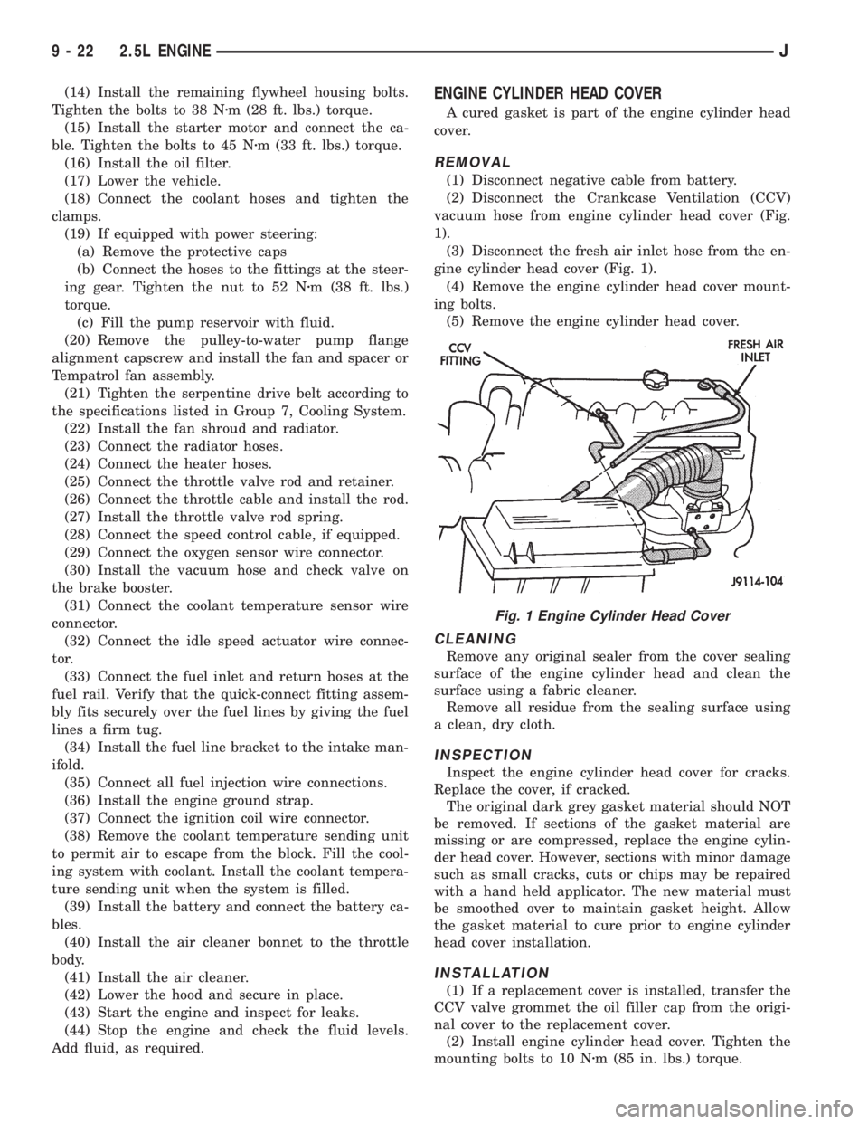
vacuum hose from engine cylinder head cover (Fig.
1).
(3) Disconnect the fresh air inlet hose from the en-
gine cylinder head cover (Fig. 1).
(4) Remove the engine cylinder head cover mount-
ing bolts.
(5) Remove the engine cylinder head cover.
CLEANING
Remove any original sealer from the cover sealing
surface of the engine cylinder head and clean the
surface using a fabric cleaner.
Remove all residue from the sealing surface using
a clean, dry cloth.
INSPECTION
Inspect the engine cylinder head cover for cracks.
Replace the cover, if cracked.
The original dark grey gasket material should NOT
be removed. If sections of the gasket material are
missing or are compressed, replace the engine cylin-
der head cover. However, sections with minor damage
such as small cracks, cuts or chips may be repaired
with a hand held applicator. The new material must
be smoothed over to maintain gasket height. Allow
the gasket material to cure prior to engine cylinder
head cover installation.
INSTALLATION
(1) If a replacement cover is installed, transfer the
CCV valve grommet the oil filler cap from the origi-
nal cover to the replacement cover.
(2) Install engine cylinder head cover. Tighten the
mounting bolts to 10 Nzm (85 in. lbs.) torque.
Fig. 1 Engine Cylinder Head Cover
9 - 22 2.5L ENGINEJ
Page 1304 of 2158
LEAK-DOWN TEST
After cleaning and inspection, test each tappet for
specified leak-down rate tolerance to ensure zero-lash
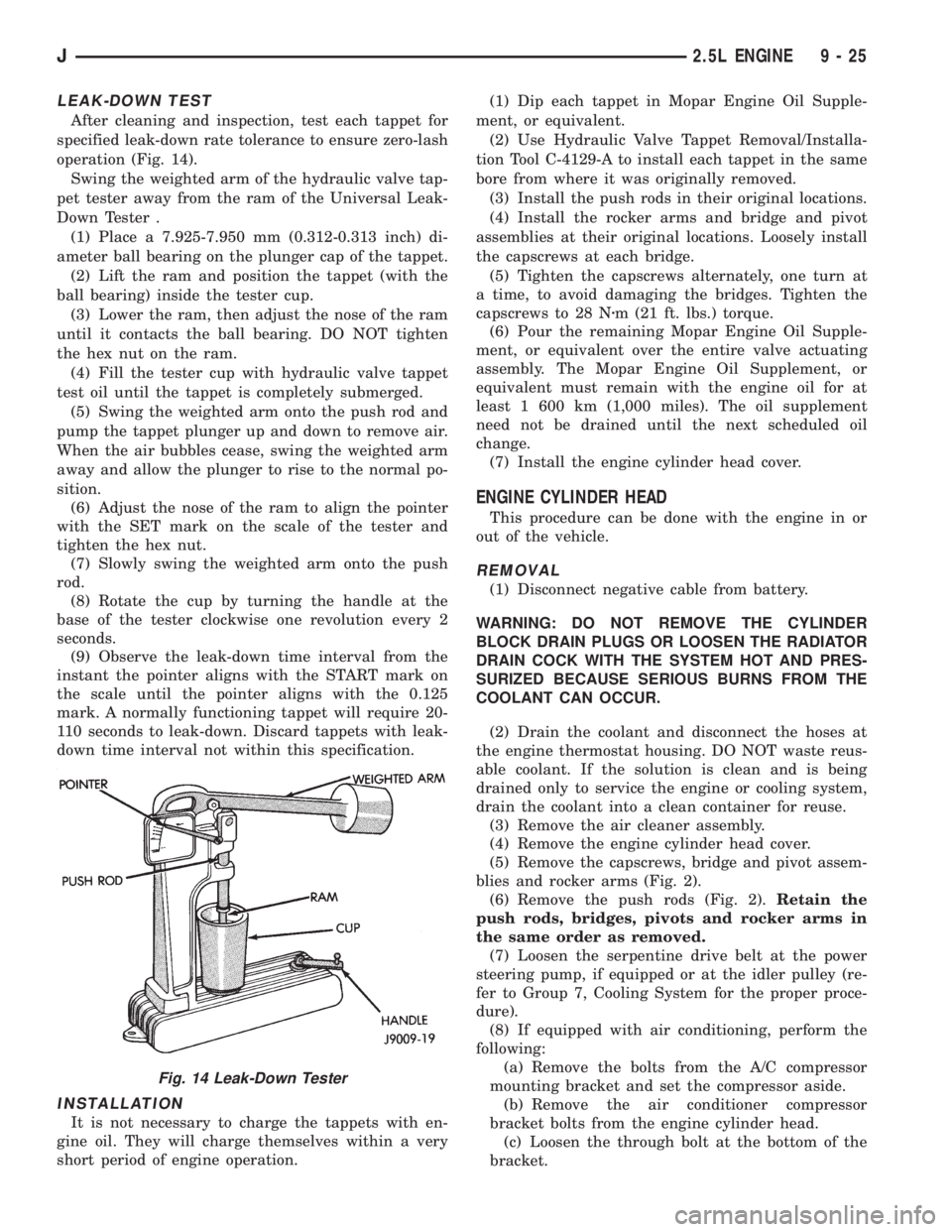
operation (Fig. 14).
Swing the weighted arm of the hydraulic valve tap-
pet tester away from the ram of the Universal Leak-
Down Tester .
(1) Place a 7.925-7.950 mm (0.312-0.313 inch) di-
ameter ball bearing on the plunger cap of the tappet.
(2) Lift the ram and position the tappet (with the
ball bearing) inside the tester cup.
(3) Lower the ram, then adjust the nose of the ram
until it contacts the ball bearing. DO NOT tighten
the hex nut on the ram.
(4) Fill the tester cup with hydraulic valve tappet
test oil until the tappet is completely submerged.
(5) Swing the weighted arm onto the push rod and
pump the tappet plunger up and down to remove air.
When the air bubbles cease, swing the weighted arm
away and allow the plunger to rise to the normal po-
sition.
(6) Adjust the nose of the ram to align the pointer
with the SET mark on the scale of the tester and
tighten the hex nut.
(7) Slowly swing the weighted arm onto the push
rod.
(8) Rotate the cup by turning the handle at the
base of the tester clockwise one revolution every 2
seconds.
(9) Observe the leak-down time interval from the
instant the pointer aligns with the START mark on
the scale until the pointer aligns with the 0.125
mark. A normally functioning tappet will require 20-
110 seconds to leak-down. Discard tappets with leak-
down time interval not within this specification.
INSTALLATION
It is not necessary to charge the tappets with en-
gine oil. They will charge themselves within a very
short period of engine operation.(1) Dip each tappet in Mopar Engine Oil Supple-
ment, or equivalent.
(2) Use Hydraulic Valve Tappet Removal/Installa-
tion Tool C-4129-A to install each tappet in the same
bore from where it was originally removed.
(3) Install the push rods in their original locations.
(4) Install the rocker arms and bridge and pivot
assemblies at their original locations. Loosely install
the capscrews at each bridge.
(5) Tighten the capscrews alternately, one turn at
a time, to avoid damaging the bridges. Tighten the
capscrews to 28 Nzm (21 ft. lbs.) torque.
(6) Pour the remaining Mopar Engine Oil Supple-
ment, or equivalent over the entire valve actuating
assembly. The Mopar Engine Oil Supplement, or
equivalent must remain with the engine oil for at
least 1 600 km (1,000 miles). The oil supplement
need not be drained until the next scheduled oil
change.
(7) Install the engine cylinder head cover.
ENGINE CYLINDER HEAD
This procedure can be done with the engine in or
out of the vehicle.
REMOVAL
(1) Disconnect negative cable from battery.
WARNING: DO NOT REMOVE THE CYLINDER
BLOCK DRAIN PLUGS OR LOOSEN THE RADIATOR
DRAIN COCK WITH THE SYSTEM HOT AND PRES-
SURIZED BECAUSE SERIOUS BURNS FROM THE
COOLANT CAN OCCUR.
(2) Drain the coolant and disconnect the hoses at
the engine thermostat housing. DO NOT waste reus-
able coolant. If the solution is clean and is being
drained only to service the engine or cooling system,
drain the coolant into a clean container for reuse.
(3) Remove the air cleaner assembly.
(4) Remove the engine cylinder head cover.
(5) Remove the capscrews, bridge and pivot assem-
blies and rocker arms (Fig. 2).
(6) Remove the push rods (Fig. 2).Retain the
push rods, bridges, pivots and rocker arms in
the same order as removed.
(7) Loosen the serpentine drive belt at the power
steering pump, if equipped or at the idler pulley (re-
fer to Group 7, Cooling System for the proper proce-
dure).
(8) If equipped with air conditioning, perform the
following:
(a) Remove the bolts from the A/C compressor
mounting bracket and set the compressor aside.
(b) Remove the air conditioner compressor
bracket bolts from the engine cylinder head.
(c) Loosen the through bolt at the bottom of the
bracket.
Fig. 14 Leak-Down Tester
J2.5L ENGINE 9 - 25