belt JEEP YJ 1995 Service And Manual Online
[x] Cancel search | Manufacturer: JEEP, Model Year: 1995, Model line: YJ, Model: JEEP YJ 1995Pages: 2158, PDF Size: 81.9 MB
Page 1384 of 2158
(2) Remove air cleaner inlet hose from throttle
plate assembly.
(3) Remove the air cleaner assembly.
(4) Remove the throttle cable, cruise control cable
(if equipped) and the transmission line pressure ca-
ble.
(5) Disconnect all electrical connectors on the in-
take manifold.
(6) Disconnect and remove the fuel supply and re-
turn lines from the fuel rail assembly (refer to Group
14, Fuel System).
(7) Loosen the accessory drive belt (refer to Group
7, Cooling System). Loosen the tensioner.
(8) Remove the power steering pump and bracket
from the intake manifold and set aside.
(9) Remove the fuel rail and injectors (refer to
Group 14, Fuel System).
(10) Raise the vehicle.
(11) Disconnect the exhaust pipe from the engine
exhaust manifold. Discard the seal.
(12) Lower the vehicle.
(13) Remove the intake manifold and engine ex-
haust manifold.
CLEANING
Clean the mating surfaces of the cylinder head and
the manifold if the original manifold is to be in-
stalled.
If the manifold is being replaced, ensure all the fit-
ting, etc. are transferred to the replacement mani-
fold.
INSTALLATION
(1) Install a new exhaust/intake manifold gasket
over the alignment dowels on the cylinder head.
(2) Position the engine exhaust manifold to the cyl-
inder head. Install fastener No.3 and finger tighten
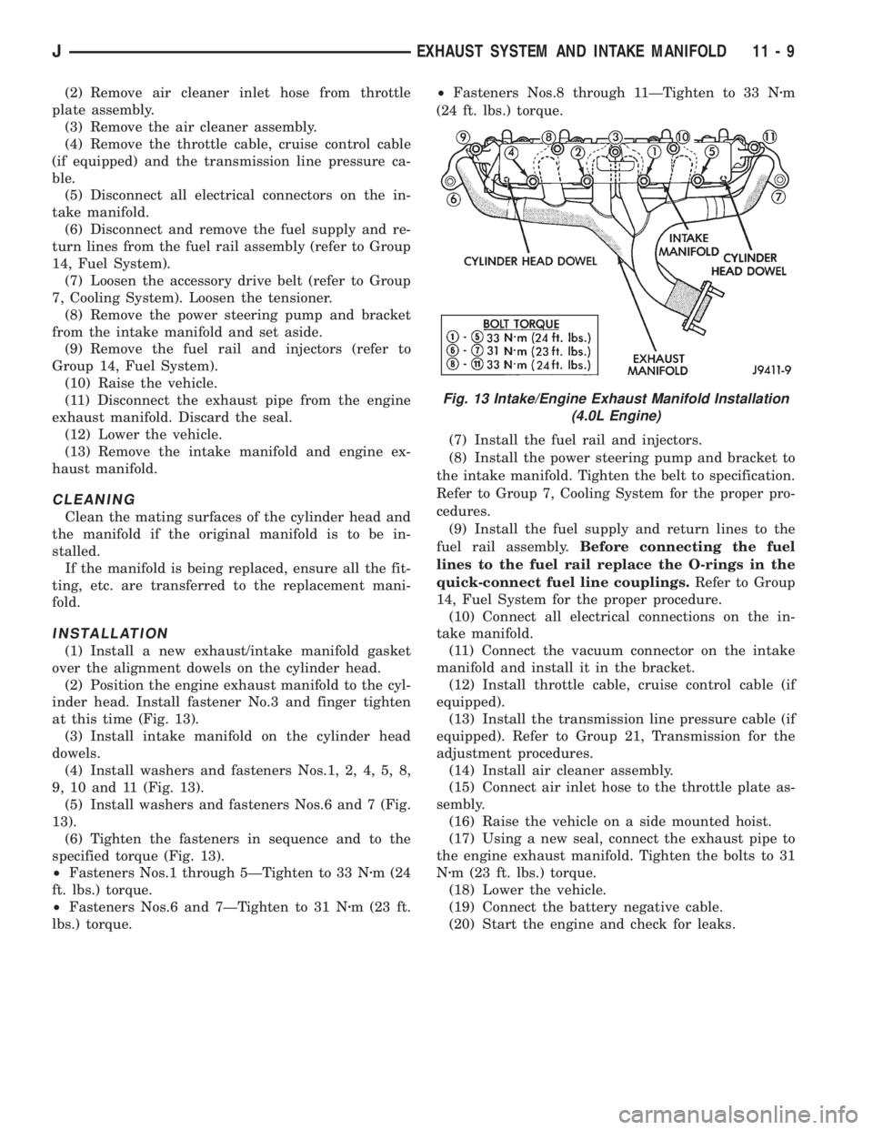
at this time (Fig. 13).
(3) Install intake manifold on the cylinder head
dowels.
(4) Install washers and fasteners Nos.1, 2, 4, 5, 8,
9, 10 and 11 (Fig. 13).
(5) Install washers and fasteners Nos.6 and 7 (Fig.
13).
(6) Tighten the fasteners in sequence and to the
specified torque (Fig. 13).
²Fasteners Nos.1 through 5ÐTighten to 33 Nzm (24
ft. lbs.) torque.
²Fasteners Nos.6 and 7ÐTighten to 31 Nzm (23 ft.
lbs.) torque.²Fasteners Nos.8 through 11ÐTighten to 33 Nzm
(24 ft. lbs.) torque.
(7) Install the fuel rail and injectors.
(8) Install the power steering pump and bracket to
the intake manifold. Tighten the belt to specification.
Refer to Group 7, Cooling System for the proper pro-
cedures.
(9) Install the fuel supply and return lines to the
fuel rail assembly.Before connecting the fuel
lines to the fuel rail replace the O-rings in the
quick-connect fuel line couplings.Refer to Group
14, Fuel System for the proper procedure.
(10) Connect all electrical connections on the in-
take manifold.
(11) Connect the vacuum connector on the intake
manifold and install it in the bracket.
(12) Install throttle cable, cruise control cable (if
equipped).
(13) Install the transmission line pressure cable (if
equipped). Refer to Group 21, Transmission for the
adjustment procedures.
(14) Install air cleaner assembly.
(15) Connect air inlet hose to the throttle plate as-
sembly.
(16) Raise the vehicle on a side mounted hoist.
(17) Using a new seal, connect the exhaust pipe to
the engine exhaust manifold. Tighten the bolts to 31
Nzm (23 ft. lbs.) torque.
(18) Lower the vehicle.
(19) Connect the battery negative cable.
(20) Start the engine and check for leaks.
Fig. 13 Intake/Engine Exhaust Manifold Installation
(4.0L Engine)
JEXHAUST SYSTEM AND INTAKE MANIFOLD 11 - 9
Page 1451 of 2158
IDLE AIR CONTROL MOTOR TEST
Idle air control (IAC) motor operation can be tested
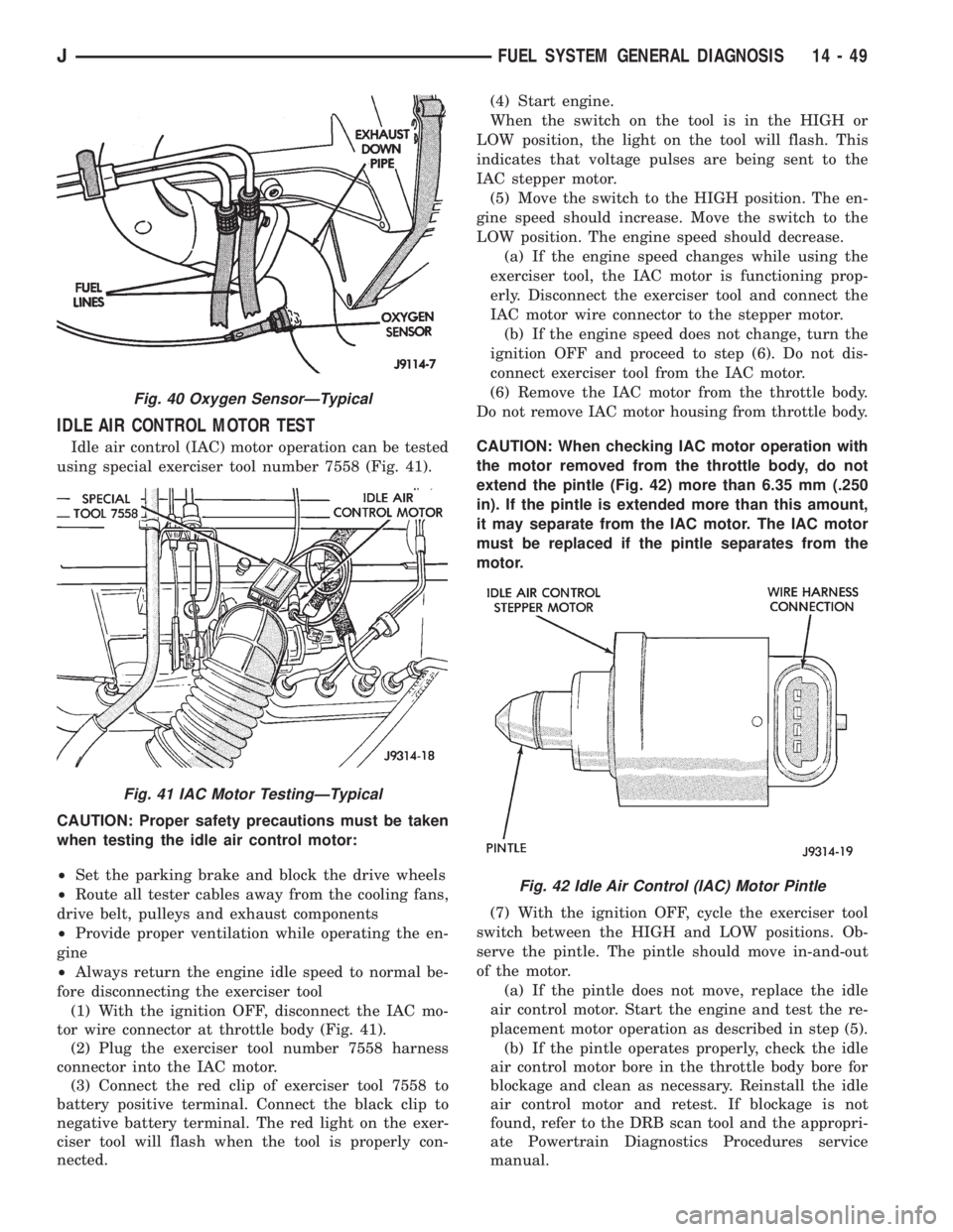
using special exerciser tool number 7558 (Fig. 41).
CAUTION: Proper safety precautions must be taken
when testing the idle air control motor:
²Set the parking brake and block the drive wheels
²Route all tester cables away from the cooling fans,
drive belt, pulleys and exhaust components
²Provide proper ventilation while operating the en-
gine
²Always return the engine idle speed to normal be-
fore disconnecting the exerciser tool
(1) With the ignition OFF, disconnect the IAC mo-
tor wire connector at throttle body (Fig. 41).
(2) Plug the exerciser tool number 7558 harness
connector into the IAC motor.
(3) Connect the red clip of exerciser tool 7558 to
battery positive terminal. Connect the black clip to
negative battery terminal. The red light on the exer-
ciser tool will flash when the tool is properly con-
nected.(4) Start engine.
When the switch on the tool is in the HIGH or
LOW position, the light on the tool will flash. This
indicates that voltage pulses are being sent to the
IAC stepper motor.
(5) Move the switch to the HIGH position. The en-
gine speed should increase. Move the switch to the
LOW position. The engine speed should decrease.
(a) If the engine speed changes while using the
exerciser tool, the IAC motor is functioning prop-
erly. Disconnect the exerciser tool and connect the
IAC motor wire connector to the stepper motor.
(b) If the engine speed does not change, turn the
ignition OFF and proceed to step (6). Do not dis-
connect exerciser tool from the IAC motor.
(6) Remove the IAC motor from the throttle body.
Do not remove IAC motor housing from throttle body.
CAUTION: When checking IAC motor operation with
the motor removed from the throttle body, do not
extend the pintle (Fig. 42) more than 6.35 mm (.250
in). If the pintle is extended more than this amount,
it may separate from the IAC motor. The IAC motor
must be replaced if the pintle separates from the
motor.
(7) With the ignition OFF, cycle the exerciser tool
switch between the HIGH and LOW positions. Ob-
serve the pintle. The pintle should move in-and-out
of the motor.
(a) If the pintle does not move, replace the idle
air control motor. Start the engine and test the re-
placement motor operation as described in step (5).
(b) If the pintle operates properly, check the idle
air control motor bore in the throttle body bore for
blockage and clean as necessary. Reinstall the idle
air control motor and retest. If blockage is not
found, refer to the DRB scan tool and the appropri-
ate Powertrain Diagnostics Procedures service
manual.
Fig. 40 Oxygen SensorÐTypical
Fig. 41 IAC Motor TestingÐTypical
Fig. 42 Idle Air Control (IAC) Motor Pintle
JFUEL SYSTEM GENERAL DIAGNOSIS 14 - 49
Page 1485 of 2158
STEERING
CONTENTS
page page
GENERAL INFORMATION.................. 1
GENERAL INFORMATION................. 48
MANUAL STEERING GEAR................ 37
POWER STEERING PUMP................. 11
POWER STEERING SYSTEM DIAGNOSIS...... 3
RECIRCULATING BALL POWER STEERING
GEAR............................... 21STEERING COLUMN GENERAL SERVICEÐXJ . 47
STEERING COLUMNÐYJ................. 58
STEERING LINKAGEÐXJ................. 16
STEERING LINKAGEÐYJ................. 19
STEERING RHD......................... 74
TORQUE SPECIFICATIONS................ 78
GENERAL INFORMATION
STEERING SYSTEM COMPONENTS
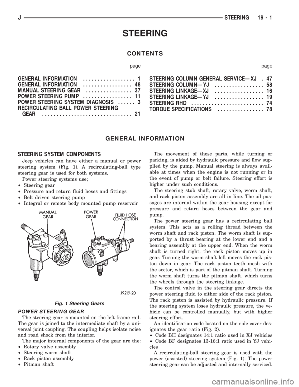
Jeep vehicles can have either a manual or power
steering system (Fig. 1). A recirculating-ball type
steering gear is used for both systems.
Power steering systems use;
²Steering gear
²Pressure and return fluid hoses and fittings
²Belt driven steering pump
²Integral or remote body mounted pump reservoir
POWER STEERING GEAR
The steering gear is mounted on the left frame rail.
The gear is joined to the intermediate shaft by a uni-
versal joint coupling. The coupling helps isolate noise
and road shock from the interior.
The major internal components of the gear are the:
²Rotary valve assembly
²Steering worm shaft
²Rack piston assembly
²Pitman shaftThe movement of these parts, while turning or
parking, is aided by hydraulic pressure and flow sup-
plied by the pump. Manual steering is always avail-
able at times when the engine is not running or in
the event of pump or belt failure. Steering effort is
higher under such conditions.
The steering stub shaft, rotary valve, worm shaft,
and rack piston assembly are all in line. The oil pas-
sages are internal within the gear housing except for
pressure and return hoses between the gear and
pump.
The power steering gear has a recirculating ball
system. This acts as a rolling thread between the
worm shaft and rack piston. The worm shaft is sup-
ported by a thrust bearing at the lower end and a
bearing assembly at the upper end. When the worm
shaft is turned right, the rack piston moves up in
gear. Turning the worm shaft left moves the rack pis-
ton down in gear. The rack piston teeth mesh with
the sector, which is part of the pitman shaft. Turning
the worm shaft turns the pitman shaft, which turns
the wheels through the steering linkage.
The control valve in the steering gear directs the
power steering fluid to either side of the rack piston.
The rack piston is assisted by hydraulic pressure. If
the steering system loses hydraulic pressure, the ve-
hicle can be controlled manually, but with higher
steering effort.
An identification code located on the side cover des-
ignates the gear ratio (Fig. 2).
²Code BH designates 14:1 ratio used in XJ vehicles
²Code BF designates 13-16:1 ratio used in YJ vehi-
cles
A recirculating-ball steering gear is used with the
power (assisted) steering system (Fig. 1). The power
steering gear can be adjusted and internally serviced.
Fig. 1 Steering Gears
JSTEERING 19 - 1
Page 1486 of 2158
POWER STEERING PUMP
Hydraulic pressure is provided for operation of the
power steering gear by a belt driven power steering
pump. The power steering pump is a constant flow
rate and displacement, vane-type pump. The internal
parts in the housing operate submerged in fluid. The
flow control orifice is part of the high pressure line
fitting. The pressure relief valve inside the flow con-
trol valve limits the pump pressure.
Power steering pumps have different pres-
sure rates and are not interchangeable with
other pumps.
The power steering pump is connected to the steer-
ing gear via high pressure and return hose. The
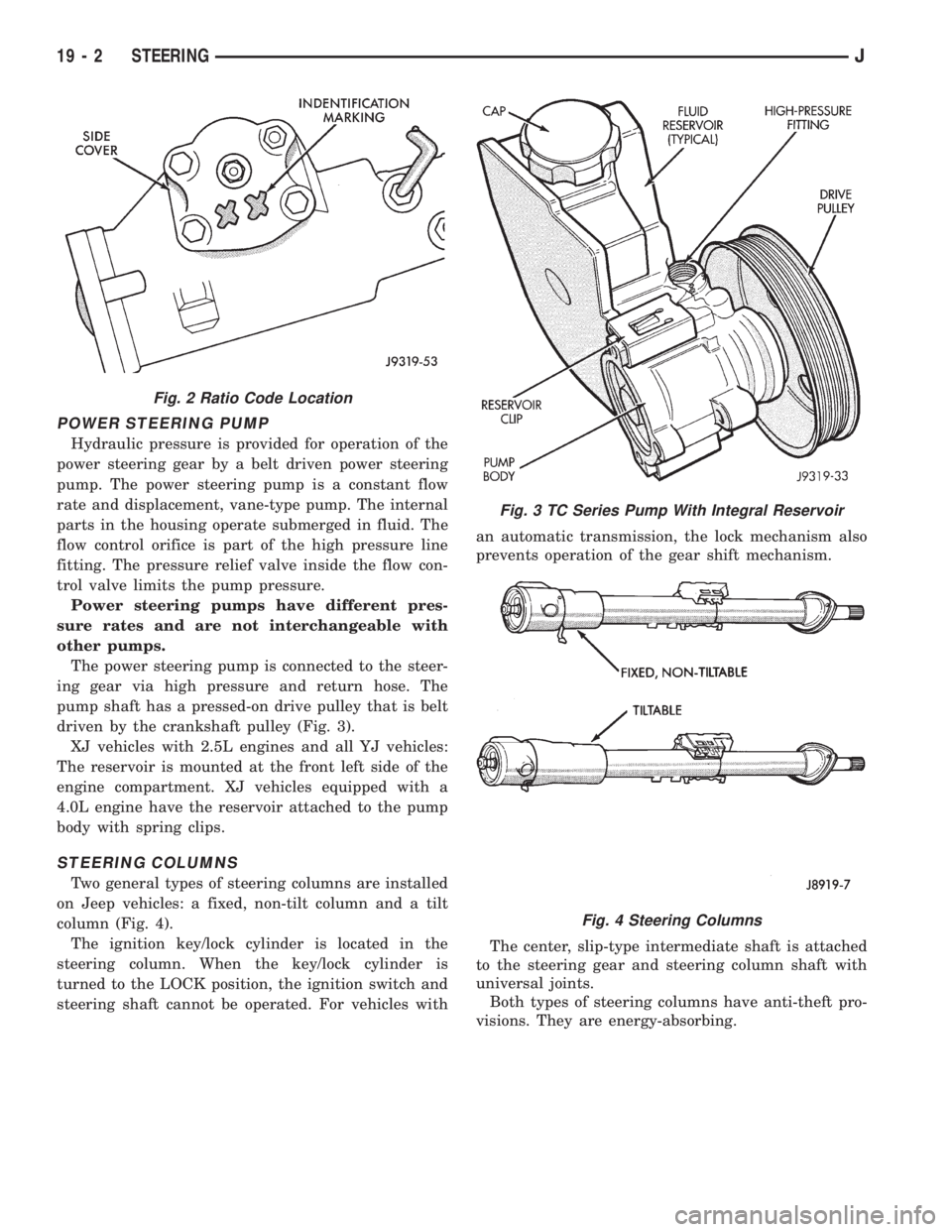
pump shaft has a pressed-on drive pulley that is belt
driven by the crankshaft pulley (Fig. 3).
XJ vehicles with 2.5L engines and all YJ vehicles:
The reservoir is mounted at the front left side of the
engine compartment. XJ vehicles equipped with a
4.0L engine have the reservoir attached to the pump
body with spring clips.
STEERING COLUMNS
Two general types of steering columns are installed
on Jeep vehicles: a fixed, non-tilt column and a tilt
column (Fig. 4).
The ignition key/lock cylinder is located in the
steering column. When the key/lock cylinder is
turned to the LOCK position, the ignition switch and
steering shaft cannot be operated. For vehicles withan automatic transmission, the lock mechanism also
prevents operation of the gear shift mechanism.
The center, slip-type intermediate shaft is attached
to the steering gear and steering column shaft with
universal joints.
Both types of steering columns have anti-theft pro-
visions. They are energy-absorbing.
Fig. 2 Ratio Code Location
Fig. 3 TC Series Pump With Integral Reservoir
Fig. 4 Steering Columns
19 - 2 STEERINGJ
Page 1487 of 2158
POWER STEERING SYSTEM DIAGNOSIS
PUMP PRESSURE TEST
(1) Check belt tension and adjust as necessary.
(2) Disconnect high pressure hose at gear or pump.
Use a container for dripping fluid.
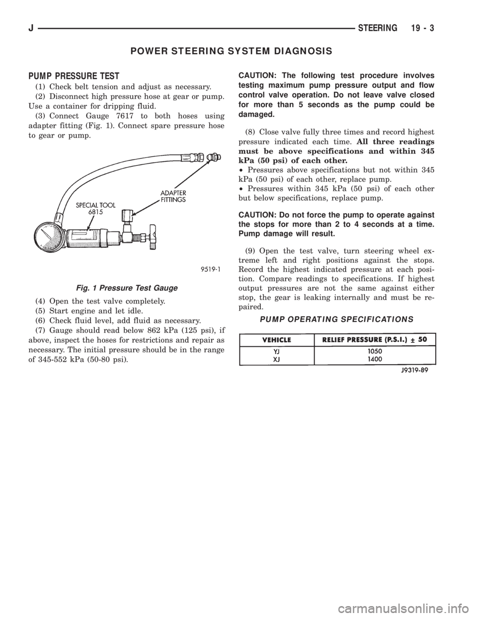
(3) Connect Gauge 7617 to both hoses using
adapter fitting (Fig. 1). Connect spare pressure hose
to gear or pump.
(4) Open the test valve completely.
(5) Start engine and let idle.
(6) Check fluid level, add fluid as necessary.
(7) Gauge should read below 862 kPa (125 psi), if
above, inspect the hoses for restrictions and repair as
necessary. The initial pressure should be in the range
of 345-552 kPa (50-80 psi).CAUTION: The following test procedure involves
testing maximum pump pressure output and flow
control valve operation. Do not leave valve closed
for more than 5 seconds as the pump could be
damaged.
(8) Close valve fully three times and record highest
pressure indicated each time.All three readings
must be above specifications and within 345
kPa (50 psi) of each other.
²Pressures above specifications but not within 345
kPa (50 psi) of each other, replace pump.
²Pressures within 345 kPa (50 psi) of each other
but below specifications, replace pump.
CAUTION: Do not force the pump to operate against
the stops for more than 2 to 4 seconds at a time.
Pump damage will result.
(9) Open the test valve, turn steering wheel ex-
treme left and right positions against the stops.
Record the highest indicated pressure at each posi-
tion. Compare readings to specifications. If highest
output pressures are not the same against either
stop, the gear is leaking internally and must be re-
paired.
Fig. 1 Pressure Test Gauge
PUMP OPERATING SPECIFICATIONS
JSTEERING 19 - 3
Page 1496 of 2158
(5) Tighten fittings at pump and gear to 35 Nzm
(25 ft. lbs.) torque.
(6) Install clamps on return hose on gear, pump
and reservoir.(7) After installation, inspect and test for fluid
leaks.
PUMP REPLACEMENT
REMOVAL
CAUTION: The drive belt tension must be released
before removing the pump. If the belt is not loos-
ened, the pump pulley could be damaged.
(1) Remove serpentine drive belt. Refer to Group 7,
Cooling for additional information.
(2) Place a drain pan under pump.
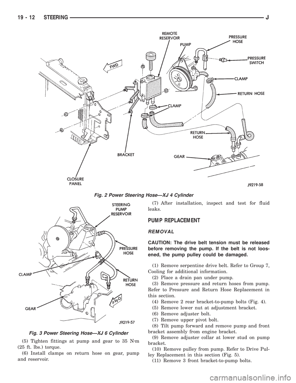
(3) Remove pressure and return hoses from pump.
Refer to Pressure and Return Hose Replacement in
this section.
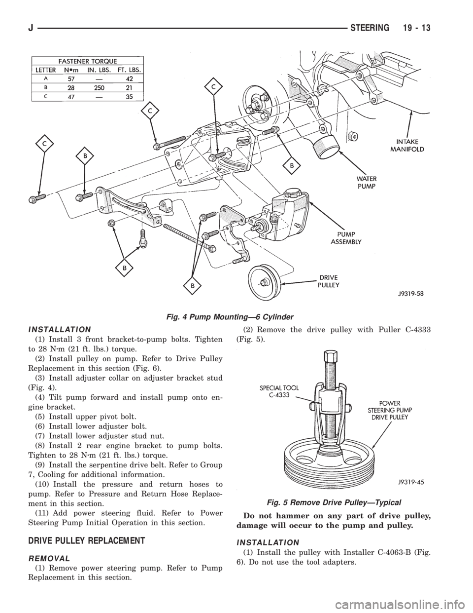
(4) Remove 2 rear bracket-to-pump bolts (Fig. 4).
(5) Remove lower nut at adjustment bracket.
(6) Remove adjuster bolt.
(7) Remove upper pivot bolt.
(8) Tilt pump forward and remove pump and front
bracket assembly from engine bracket.
(9) Remove adjuster collar at lower stud on pump
bracket.
(10) Remove pulley from pump. Refer to Drive Pul-
ley Replacement in this section (Fig. 5).
(11) Remove 3 front bracket-to-pump bolts.
Fig. 2 Power Steering HoseÐXJ 4 Cylinder
Fig. 3 Power Steering HoseÐXJ 6 Cylinder
19 - 12 STEERINGJ
Page 1497 of 2158
INSTALLATION
(1) Install 3 front bracket-to-pump bolts. Tighten
to 28 Nzm (21 ft. lbs.) torque.
(2) Install pulley on pump. Refer to Drive Pulley
Replacement in this section (Fig. 6).
(3) Install adjuster collar on adjuster bracket stud
(Fig. 4).
(4) Tilt pump forward and install pump onto en-
gine bracket.
(5) Install upper pivot bolt.
(6) Install lower adjuster bolt.
(7) Install lower adjuster stud nut.
(8) Install 2 rear engine bracket to pump bolts.
Tighten to 28 Nzm (21 ft. lbs.) torque.
(9) Install the serpentine drive belt. Refer to Group
7, Cooling for additional information.
(10) Install the pressure and return hoses to
pump. Refer to Pressure and Return Hose Replace-
ment in this section.
(11) Add power steering fluid. Refer to Power
Steering Pump Initial Operation in this section.
DRIVE PULLEY REPLACEMENT
REMOVAL
(1) Remove power steering pump. Refer to Pump
Replacement in this section.(2) Remove the drive pulley with Puller C-4333
(Fig. 5).
Do not hammer on any part of drive pulley,
damage will occur to the pump and pulley.
INSTALLATION
(1) Install the pulley with Installer C-4063-B (Fig.
6). Do not use the tool adapters.
Fig. 4 Pump MountingÐ6 Cylinder
Fig. 5 Remove Drive PulleyÐTypical
JSTEERING 19 - 13
Page 1498 of 2158
(2) Be sure tool and pulley remain aligned and
NOT cocked with the pump shaft.
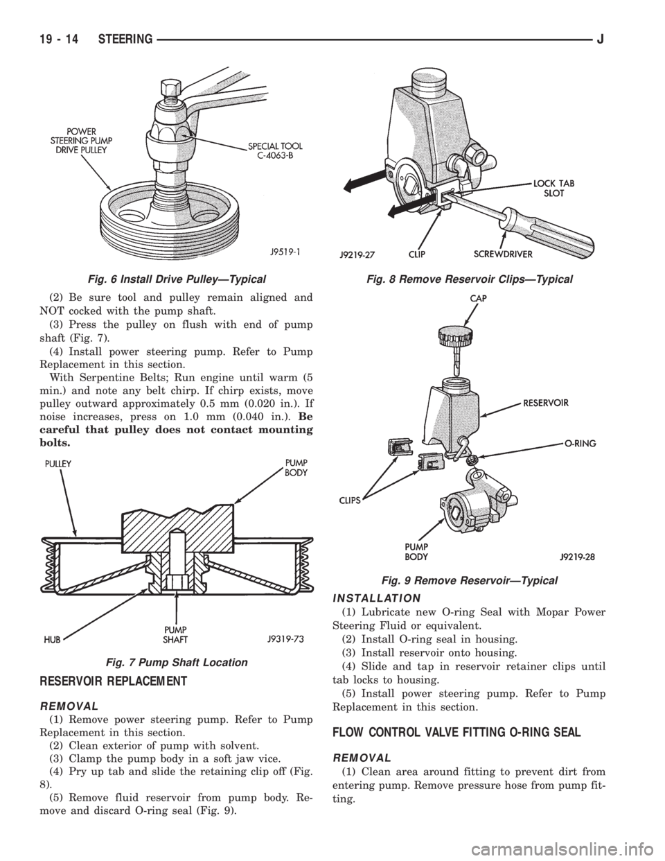
(3) Press the pulley on flush with end of pump
shaft (Fig. 7).
(4) Install power steering pump. Refer to Pump
Replacement in this section.
With Serpentine Belts; Run engine until warm (5
min.) and note any belt chirp. If chirp exists, move
pulley outward approximately 0.5 mm (0.020 in.). If
noise increases, press on 1.0 mm (0.040 in.).Be
careful that pulley does not contact mounting
bolts.
RESERVOIR REPLACEMENT
REMOVAL
(1) Remove power steering pump. Refer to Pump
Replacement in this section.
(2) Clean exterior of pump with solvent.
(3) Clamp the pump body in a soft jaw vice.
(4) Pry up tab and slide the retaining clip off (Fig.
8).
(5) Remove fluid reservoir from pump body. Re-
move and discard O-ring seal (Fig. 9).
INSTALLATION
(1) Lubricate new O-ring Seal with Mopar Power
Steering Fluid or equivalent.
(2) Install O-ring seal in housing.
(3) Install reservoir onto housing.
(4) Slide and tap in reservoir retainer clips until
tab locks to housing.
(5) Install power steering pump. Refer to Pump
Replacement in this section.
FLOW CONTROL VALVE FITTING O-RING SEAL
REMOVAL
(1) Clean area around fitting to prevent dirt from
entering pump. Remove pressure hose from pump fit-
ting.
Fig. 6 Install Drive PulleyÐTypical
Fig. 7 Pump Shaft Location
Fig. 8 Remove Reservoir ClipsÐTypical
Fig. 9 Remove ReservoirÐTypical
19 - 14 STEERINGJ
Page 1559 of 2158
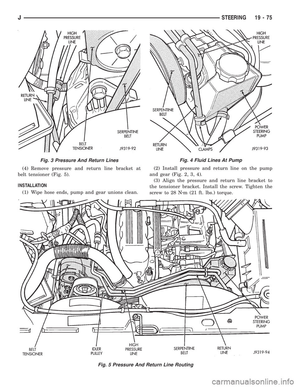
(4) Remove pressure and return line bracket at
belt tensioner (Fig. 5).
INSTALLATION
(1) Wipe hose ends, pump and gear unions clean.(2) Install pressure and return line on the pump
and gear (Fig. 2, 3, 4).
(3) Align the pressure and return line bracket to
the tensioner bracket. Install the screw. Tighten the
screw to 28 Nzm (21 ft. lbs.) torque.
Fig. 4 Fluid Lines At Pump
Fig. 5 Pressure And Return Line Routing
Fig. 3 Pressure And Return Lines
JSTEERING 19 - 75
Page 1560 of 2158
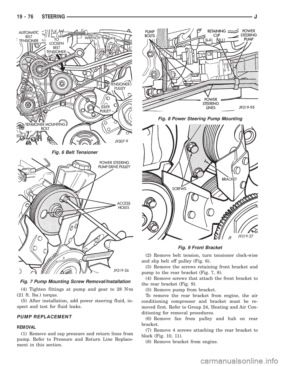
(4) Tighten fittings at pump and gear to 28 Nzm
(21 ft. lbs.) torque.
(5) After installation, add power steering fluid, in-
spect and test for fluid leaks.
PUMP REPLACEMENT
REMOVAL
(1) Remove and cap pressure and return lines from
pump. Refer to Pressure and Return Line Replace-
ment in this section.(2) Remove belt tension, turn tensioner clock-wise
and slip belt off pulley (Fig. 6).
(3) Remove the screws retaining front bracket and
pump to the rear bracket (Fig. 7, 8).
(4) Remove screws that attach the front bracket to
the rear bracket (Fig. 9).
(5) Remove pump from bracket.
To remove the rear bracket from engine, the air
conditioning compressor and bracket must be re-
moved first. Refer to Group 24, Heating and Air Con-
ditioning for removal procedures.
(6) Remove fan from pulley and hub on rear
bracket.
(7) Remove 4 screws attaching the rear bracket to
block (Fig. 10, 11).
(8) Remove bracket from engine.
Fig. 6 Belt Tensioner
Fig. 7 Pump Mounting Screw Removal/Installation
Fig. 8 Power Steering Pump Mounting
Fig. 9 Front Bracket
19 - 76 STEERINGJ