belt JEEP YJ 1995 Service And Owners Manual
[x] Cancel search | Manufacturer: JEEP, Model Year: 1995, Model line: YJ, Model: JEEP YJ 1995Pages: 2158, PDF Size: 81.9 MB
Page 1561 of 2158
INSTALLATION
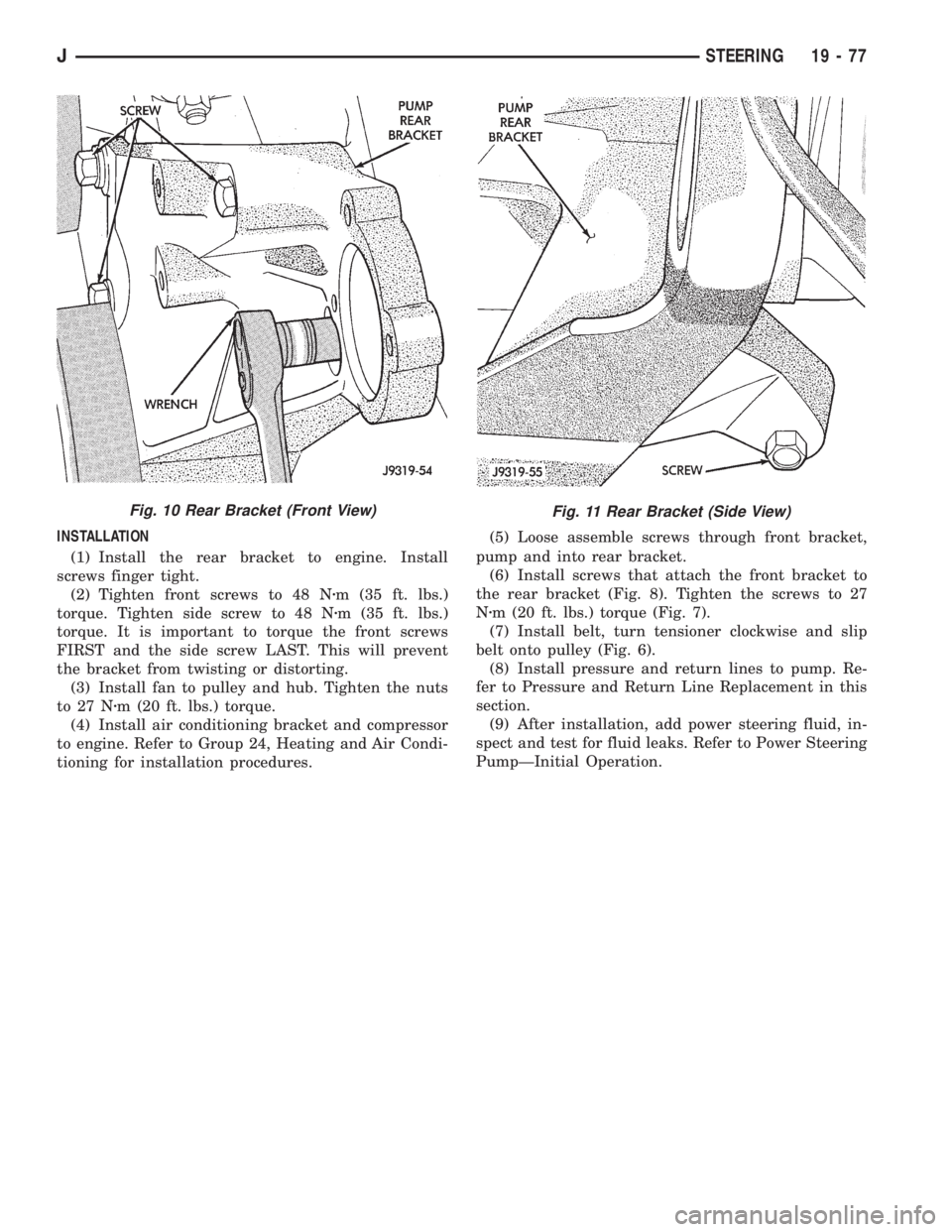
(1) Install the rear bracket to engine. Install
screws finger tight.
(2) Tighten front screws to 48 Nzm (35 ft. lbs.)
torque. Tighten side screw to 48 Nzm (35 ft. lbs.)
torque. It is important to torque the front screws
FIRST and the side screw LAST. This will prevent
the bracket from twisting or distorting.
(3) Install fan to pulley and hub. Tighten the nuts
to 27 Nzm (20 ft. lbs.) torque.
(4) Install air conditioning bracket and compressor
to engine. Refer to Group 24, Heating and Air Condi-
tioning for installation procedures.(5) Loose assemble screws through front bracket,
pump and into rear bracket.
(6) Install screws that attach the front bracket to
the rear bracket (Fig. 8). Tighten the screws to 27
Nzm (20 ft. lbs.) torque (Fig. 7).
(7) Install belt, turn tensioner clockwise and slip
belt onto pulley (Fig. 6).
(8) Install pressure and return lines to pump. Re-
fer to Pressure and Return Line Replacement in this
section.
(9) After installation, add power steering fluid, in-
spect and test for fluid leaks. Refer to Power Steering
PumpÐInitial Operation.
Fig. 11 Rear Bracket (Side View)Fig. 10 Rear Bracket (Front View)
JSTEERING 19 - 77
Page 1917 of 2158
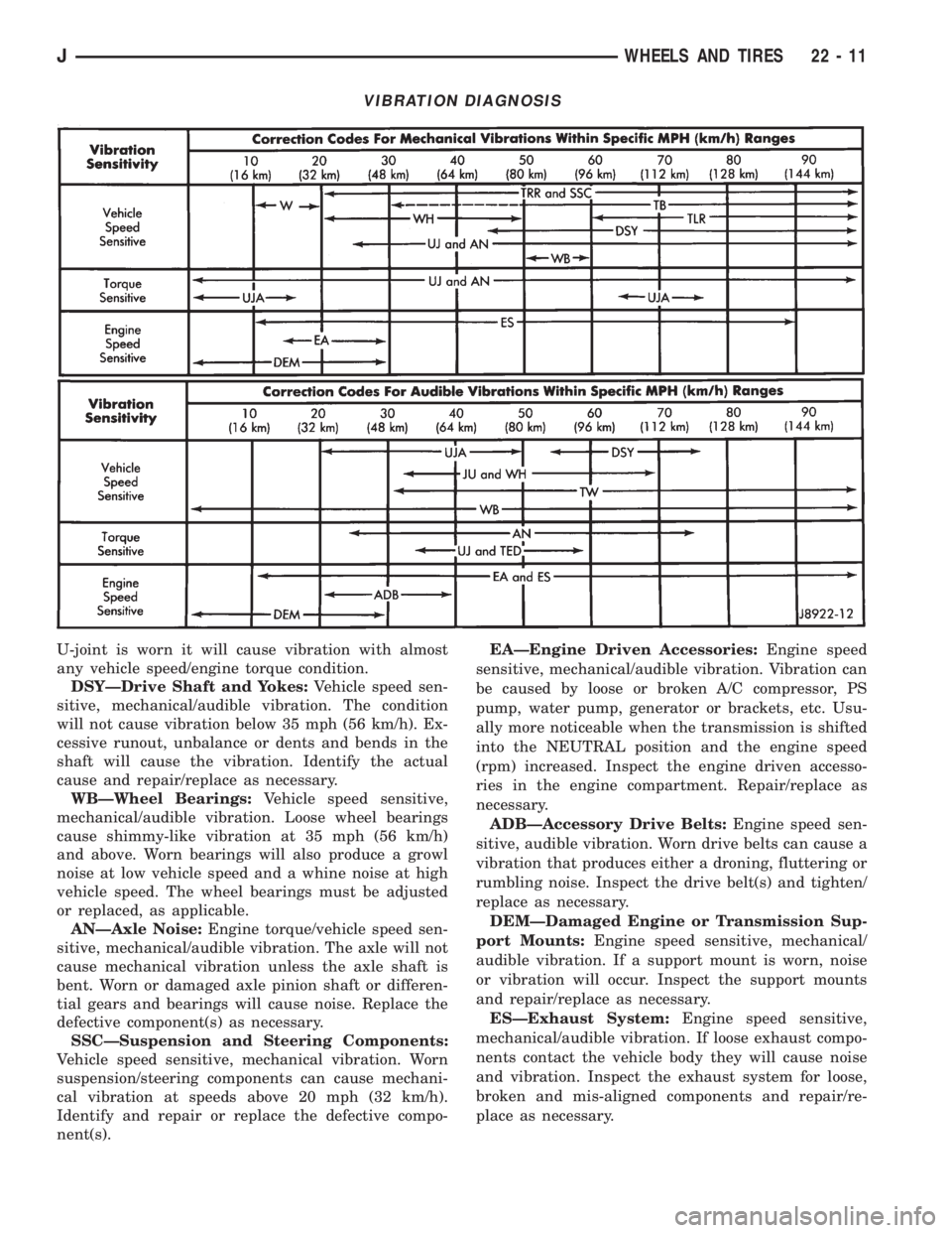
U-joint is worn it will cause vibration with almost
any vehicle speed/engine torque condition.
DSYÐDrive Shaft and Yokes:Vehicle speed sen-
sitive, mechanical/audible vibration. The condition
will not cause vibration below 35 mph (56 km/h). Ex-
cessive runout, unbalance or dents and bends in the
shaft will cause the vibration. Identify the actual
cause and repair/replace as necessary.
WBÐWheel Bearings:Vehicle speed sensitive,
mechanical/audible vibration. Loose wheel bearings
cause shimmy-like vibration at 35 mph (56 km/h)
and above. Worn bearings will also produce a growl
noise at low vehicle speed and a whine noise at high
vehicle speed. The wheel bearings must be adjusted
or replaced, as applicable.
ANÐAxle Noise:Engine torque/vehicle speed sen-
sitive, mechanical/audible vibration. The axle will not
cause mechanical vibration unless the axle shaft is
bent. Worn or damaged axle pinion shaft or differen-
tial gears and bearings will cause noise. Replace the
defective component(s) as necessary.
SSCÐSuspension and Steering Components:
Vehicle speed sensitive, mechanical vibration. Worn
suspension/steering components can cause mechani-
cal vibration at speeds above 20 mph (32 km/h).
Identify and repair or replace the defective compo-
nent(s).EAÐEngine Driven Accessories:Engine speed
sensitive, mechanical/audible vibration. Vibration can
be caused by loose or broken A/C compressor, PS
pump, water pump, generator or brackets, etc. Usu-
ally more noticeable when the transmission is shifted
into the NEUTRAL position and the engine speed
(rpm) increased. Inspect the engine driven accesso-
ries in the engine compartment. Repair/replace as
necessary.
ADBÐAccessory Drive Belts:Engine speed sen-
sitive, audible vibration. Worn drive belts can cause a
vibration that produces either a droning, fluttering or
rumbling noise. Inspect the drive belt(s) and tighten/
replace as necessary.
DEMÐDamaged Engine or Transmission Sup-
port Mounts:Engine speed sensitive, mechanical/
audible vibration. If a support mount is worn, noise
or vibration will occur. Inspect the support mounts
and repair/replace as necessary.
ESÐExhaust System:Engine speed sensitive,
mechanical/audible vibration. If loose exhaust compo-
nents contact the vehicle body they will cause noise
and vibration. Inspect the exhaust system for loose,
broken and mis-aligned components and repair/re-
place as necessary.
VIBRATION DIAGNOSIS
JWHEELS AND TIRES 22 - 11
Page 1961 of 2158
(4) Tighten the regulator-to-glass screw to 4 Nzm
(36 in-lbs) torque.
(5) Install the glass channel bottom screw (Fig.
17). Tighten screw to 9 Nzm (7 ft-lbs) torque.(6) Attach the door waterdam to the door inner
panel with sealant.
(7) Install the trim panel.
FRONT DOOR WINDOW GLASSÐXJ
REMOVAL
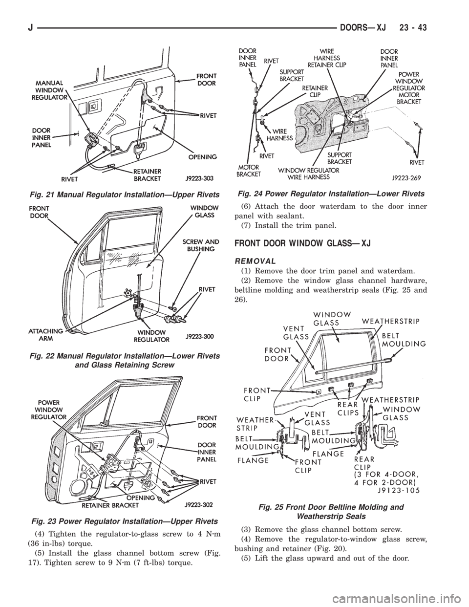
(1) Remove the door trim panel and waterdam.
(2) Remove the window glass channel hardware,
beltline molding and weatherstrip seals (Fig. 25 and
26).
(3) Remove the glass channel bottom screw.
(4) Remove the regulator-to-window glass screw,
bushing and retainer (Fig. 20).
(5) Lift the glass upward and out of the door.
Fig. 21 Manual Regulator InstallationÐUpper Rivets
Fig. 22 Manual Regulator InstallationÐLower Rivets
and Glass Retaining Screw
Fig. 23 Power Regulator InstallationÐUpper Rivets
Fig. 24 Power Regulator InstallationÐLower Rivets
Fig. 25 Front Door Beltline Molding and
Weatherstrip Seals
JDOORSÐXJ 23 - 43
Page 1962 of 2158
INSTALLATION
(1) Position the glass in the door and install the
regulator-to-glass retainer, bushing and screw.
(2) Tighten the screw to 4 Nzm (36 in-lbs) torque.
(3) Install the channel bottom screw. Tighten the
screw to 9 Nzm (7 ft-lbs) torque.
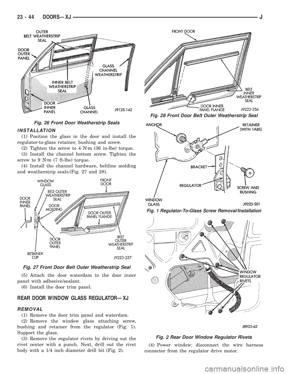
(4) Install the channel hardware, beltline molding
and weatherstrip seals.(Fig. 27 and 28).
(5) Attach the door waterdam to the door inner
panel with adhesive/sealant.
(6) Install the door trim panel.
REAR DOOR WINDOW GLASS REGULATORÐXJ
REMOVAL
(1) Remove the door trim panel and waterdam.
(2) Remove the window glass attaching screw,
bushing and retainer from the regulator (Fig. 1).
Support the glass.
(3) Remove the regulator rivets by driving out the
rivet center with a punch. Next, drill out the rivet
body with a 1/4 inch diameter drill bit (Fig. 2).(4) Power window: disconnect the wire harness
connector from the regulator drive motor.
Fig. 26 Front Door Weatherstrip Seals
Fig. 27 Front Door Belt Outer Weatherstrip Seal
Fig. 28 Front Door Belt Outer Weatherstrip Seal
Fig. 1 Regulator-To-Glass Screw Removal/Installation
Fig. 2 Rear Door Window Regulator Rivets
23 - 44 DOORSÐXJJ
Page 1963 of 2158
(5) Remove the regulator and drive motor, if
equipped.
INSTALLATION
(1) Position window regulator and, if equipped,
drive motor within the door panels.
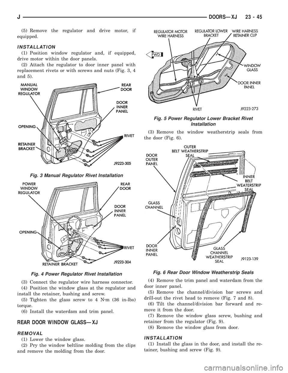
(2) Attach the regulator to door inner panel with
replacement rivets or with screws and nuts (Fig. 3, 4
and 5).
(3) Connect the regulator wire harness connector.
(4) Position the window glass at the regulator and
install the retainer, bushing and screw.
(5) Tighten the glass screw to 4 Nzm (36 in-lbs)
torque.
(6) Install the waterdam and trim panel.
REAR DOOR WINDOW GLASSÐXJ
REMOVAL
(1) Lower the window glass.
(2) Pry the window beltline molding from the clips
and remove the molding from the door.(3) Remove the window weatherstrip seals from
the door (Fig. 6).
(4) Remove the trim panel and waterdam from the
door inner panel.
(5) Remove the channel/division bar screws and
drill-out the rivet head to remove (Fig. 7 and 8).
(6) Tilt the channel/division bar forward and re-
move it from the door.
(7) Remove the window glass screw, bushing and
retainer from the regulator (Fig. 9).
(8) Remove the window glass from door.INSTALLATION
(1) Install the glass in the door, and install the re-
tainer, bushing and screw (Fig. 9).
Fig. 3 Manual Regulator Rivet Installation
Fig. 4 Power Regulator Rivet Installation
Fig. 5 Power Regulator Lower Bracket Rivet
Installation
Fig. 6 Rear Door Window Weatherstrip Seals
JDOORSÐXJ 23 - 45
Page 1964 of 2158
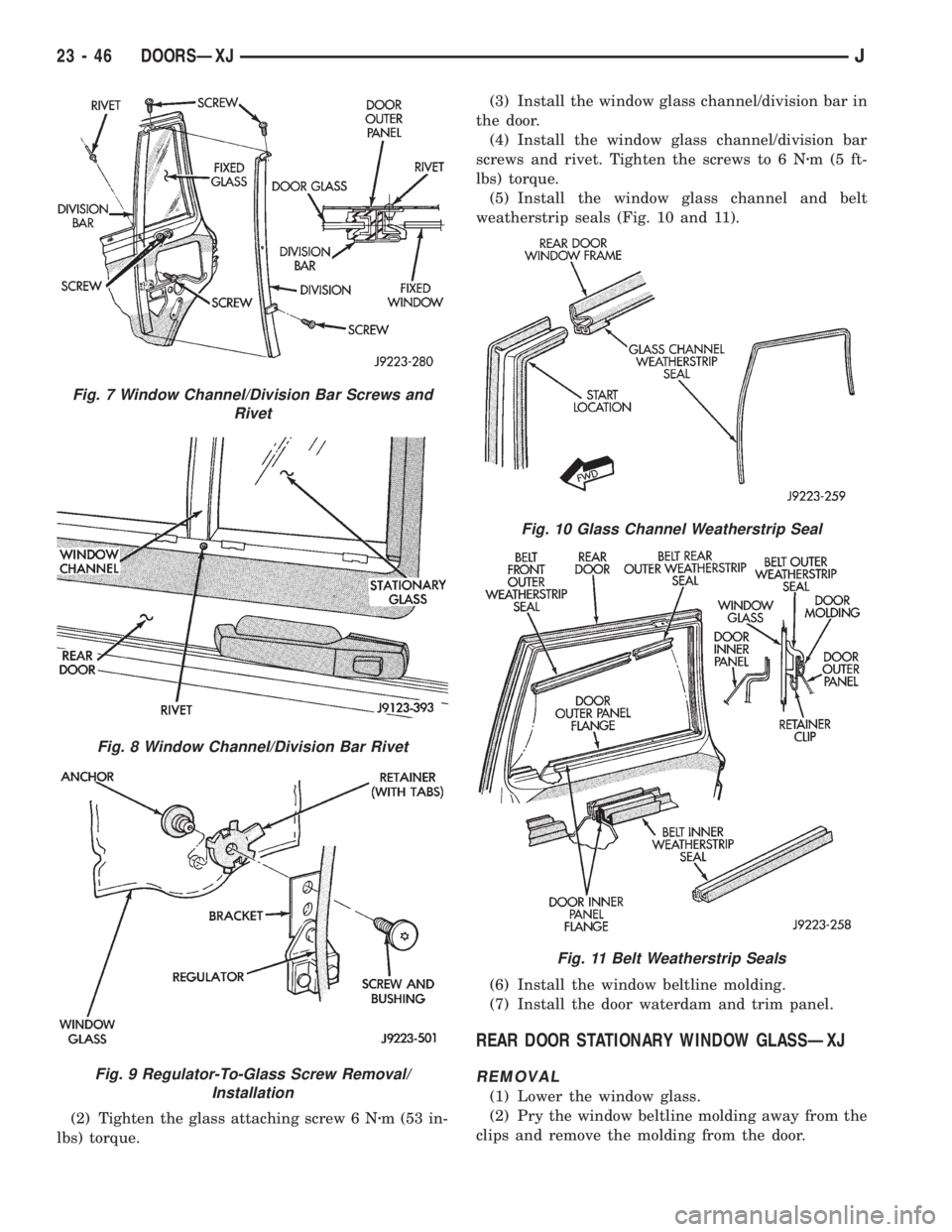
(2) Tighten the glass attaching screw 6 Nzm (53 in-
lbs) torque.(3) Install the window glass channel/division bar in
the door.
(4) Install the window glass channel/division bar
screws and rivet. Tighten the screws to 6 Nzm(5ft-
lbs) torque.
(5) Install the window glass channel and belt
weatherstrip seals (Fig. 10 and 11).
(6) Install the window beltline molding.
(7) Install the door waterdam and trim panel.
REAR DOOR STATIONARY WINDOW GLASSÐXJ
REMOVAL
(1) Lower the window glass.
(2) Pry the window beltline molding away from the
clips and remove the molding from the door.
Fig. 7 Window Channel/Division Bar Screws and
Rivet
Fig. 8 Window Channel/Division Bar Rivet
Fig. 9 Regulator-To-Glass Screw Removal/
Installation
Fig. 10 Glass Channel Weatherstrip Seal
Fig. 11 Belt Weatherstrip Seals
23 - 46 DOORSÐXJJ
Page 1965 of 2158
(3) Remove the window weatherstrip seals from
the door.
(4) Remove the trim panel and waterdam from
door inner panel.
(5) Remove the channel/division bar screws. Drill
out the rivet head to remove it from the inner panel.
(6) Tilt the channel/division bar forward and re-
move it from the door.
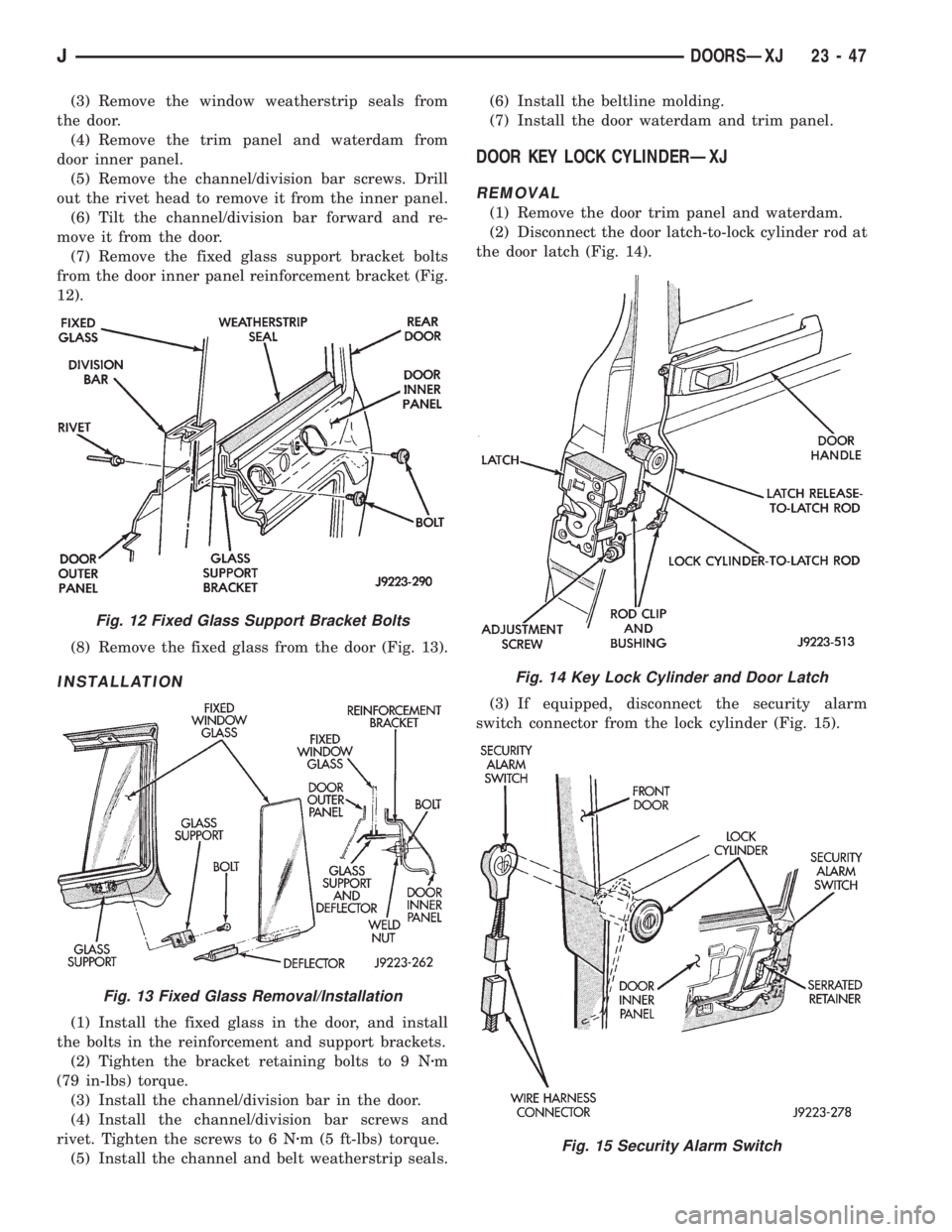
(7) Remove the fixed glass support bracket bolts
from the door inner panel reinforcement bracket (Fig.
12).
(8) Remove the fixed glass from the door (Fig. 13).
INSTALLATION
(1) Install the fixed glass in the door, and install
the bolts in the reinforcement and support brackets.
(2) Tighten the bracket retaining bolts to 9 Nzm
(79 in-lbs) torque.
(3) Install the channel/division bar in the door.
(4) Install the channel/division bar screws and
rivet. Tighten the screws to 6 Nzm (5 ft-lbs) torque.
(5) Install the channel and belt weatherstrip seals.(6) Install the beltline molding.
(7) Install the door waterdam and trim panel.
DOOR KEY LOCK CYLINDERÐXJ
REMOVAL
(1) Remove the door trim panel and waterdam.
(2) Disconnect the door latch-to-lock cylinder rod at
the door latch (Fig. 14).
(3) If equipped, disconnect the security alarm
switch connector from the lock cylinder (Fig. 15).
Fig. 12 Fixed Glass Support Bracket Bolts
Fig. 13 Fixed Glass Removal/Installation
Fig. 14 Key Lock Cylinder and Door Latch
Fig. 15 Security Alarm Switch
JDOORSÐXJ 23 - 47
Page 1975 of 2158
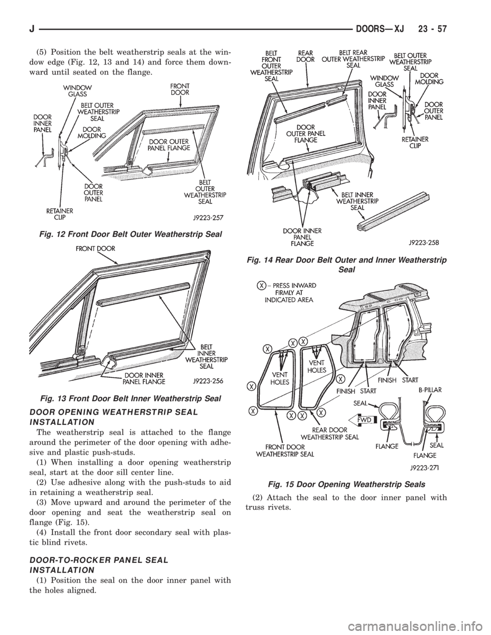
(5) Position the belt weatherstrip seals at the win-
dow edge (Fig. 12, 13 and 14) and force them down-
ward until seated on the flange.
DOOR OPENING WEATHERSTRIP SEAL
INSTALLATION
The weatherstrip seal is attached to the flange
around the perimeter of the door opening with adhe-
sive and plastic push-studs.
(1) When installing a door opening weatherstrip
seal, start at the door sill center line.
(2) Use adhesive along with the push-studs to aid
in retaining a weatherstrip seal.
(3) Move upward and around the perimeter of the
door opening and seat the weatherstrip seal on
flange (Fig. 15).
(4) Install the front door secondary seal with plas-
tic blind rivets.
DOOR-TO-ROCKER PANEL SEAL
INSTALLATION
(1) Position the seal on the door inner panel with
the holes aligned.(2) Attach the seal to the door inner panel with
truss rivets.
Fig. 12 Front Door Belt Outer Weatherstrip Seal
Fig. 13 Front Door Belt Inner Weatherstrip Seal
Fig. 14 Rear Door Belt Outer and Inner Weatherstrip
Seal
Fig. 15 Door Opening Weatherstrip Seals
JDOORSÐXJ 23 - 57
Page 1990 of 2158
(6) If the pinchweld flanges require repair, remove
the windshield glass and straighten, align, or repair
the flange(s) as necessary.
(7) Position the windshield in the opening and in-
spect the windshield fit again. Mark the windshield
final position on the glass and body with a wax pen-
cil (or use masking tape). The marks (or masking
tape) will be used for installation alignment refer-
ence.
(8) If the replacement windshield does not have
blackout primer:
²Attach a 25-mm (1-in) wide masking tape band
around the interior side of glass 16 mm (5/8 in)
from edge of glass (Fig. 2).
²Do not attach tape along the bottom of the glass
and attach only to the inside of glass.
²Thoroughly mix and apply blackout primer to the
16 mm (5/8 in) surface area around the interior
side of the glass (Fig. 4).
²Allow the primer to dry for at least 10-12 minutes.
(9) Apply a small amount of adhesive to the bot-
tom support spacers and attach the support spacers
to the bottom of the windshield, 170 mm inboard
from the outer windshield edge (Fig. 6).
(10) Cut the urethane applicator nozzle (Fig. 7).
(11) Apply a continuous bead of urethane to the
surface area with blackout primer on the interior
side of glass. The bead should be 9-mm (3/8-in) wide
by 12.7-mm (1/2-in) deep for best results.CAUTION: Be prepared to install the windshield im-
mediately after applying the adhesive, as the adhe-
sive will begin to cure in less than 10 minutes.
(12) Align the windshield with the wax pencil in-
stallation alignment reference marks (or the tape
strips). Position the windshield on pinchweld flanges
and spacers.
(13) Force the windshield inward just enough to
wet-out and set the urethane. Use care to avoid ex-
cessive squeeze-out of adhesive.
(14) Water test the windshield with a water spray
after installation. Do not direct high pressure
streams of water directly at the urethane. If any
leaks are detected, apply urethane as necessary.
(15) If used, remove the masking tape from the in-
ner surface of glass.
(16) Install all components and clean the vehicle. If
necessary, refer to the installation procedures.
(17) Open the vehicle windows to prevent interior
pressure while the urethane adhesive is curing.If
not vented, pressure in the interior of vehicle
will interfere with glass bonding.
(18) Install the rearview mirror on the bracket.
REAR DOOR STATIONARY WINDOW GLASS
REMOVAL
(1) Lower the window glass.
(2) Pry the window beltline molding away from the
clips and remove the molding from the door.
(3) Remove the window weatherstrip seals from
the door.
23 - 72 STATIONARY WINDOW GLASSÐXJJ1995 Jeep Cherokee/Wrangler
Publication No. 81-370-5146
TSB 26-05-95 July, 1995
Page 1998 of 2158
INTERIOR COMPONENTS
INDEX
page page
Assist HandleÐXJ........................ 89
B/C-Pillar and Liftgate Pillar Trim CoversÐXJ.... 88
Bucket Seat Cushion and CoverÐXJ........... 81
Bucket Seat PlatformÐXJ................... 82
Bucket Seatback Cover and FrameÐXJ........ 81
Cargo BarrierÐXJ........................ 101
Cargo LampÐXJ......................... 94
Carpets and Floor MatsÐXJ................. 99
Dome LampÐXJ......................... 93
Front Bucket SeatsÐXJ.................... 81
Front Carpet/MatÐXJ...................... 99
Front Inner Scuff Plate/Cowl Side Trim PanelÐXJ . 86
Front Shoulder Belt/BuckleÐXJ............... 90
Full Floor ConsoleÐXJ..................... 95
HeadlinerÐXJ............................ 92
I/P Ash Receiver Tray LampÐXJ.............. 80
Instrument Cluster BezelÐXJ................ 80
Interior Trim Panels and Scuff PlatesÐXJ....... 84
Jack StorageÐXJ......................... 97
Keyless Entry ReceiverÐXJ................. 93Mini-Console with Floor ShiftÐXJ............. 94
Mini-Floor ConsoleÐXJ..................... 94
Outer Scuff PlatesÐXJ..................... 89
Overhead ConsoleÐXJ..................... 93
Parking Brake Handle CoverÐXJ............. 94
Quarter and Wheelhouse Trim PanelsÐXJ...... 87
Quarter Trim Panel ExtensionÐXJ............. 87
Rear Carpet/MatÐXJ..................... 100
Rear Seat Cushion CoverÐXJ............... 82
Rear Seat CushionÐXJ.................... 82
Rear Seatback CoverÐXJ................... 84
Rear Seatback Latch Striker and BumperÐXJ.... 84
Rear SeatbackÐXJ........................ 83
Rear Shoulder/Lap Belt/BuckleÐXJ............ 91
Sound BarÐXJ........................... 94
Spare Tire/Wheel Holddown and Floor
BracketsÐXJ........................... 98
SunvisorsÐXJ........................... 93
Windshield Side MoldingÐXJ................ 86
INSTRUMENT CLUSTER BEZELÐXJ
REMOVAL
(1) Remove the bezel retaining screws (Fig. 1).
(2) Separate the bezel from the U-clips and remove
it from the upper section of the instrument panel.
(3) If necessary, remove or install rocker switch
cover plates.
INSTALLATION
(1) Position the bezel on the upper instrument
panel and engage it with the U-clips.
(2) Install the bezel retaining screws. Tighten thescrews with 1 Nzm (11 in-lbs) torque.
For service procedures regarding individual I/P
components refer to Group 8, Electrical.
I/P ASH RECEIVER TRAY LAMPÐXJ
REMOVAL
(1) Remove the ash receiver tray from instrument
panel (Fig. 2).
(2) Remove the lamp retaining screw from the ash
receiver tray cavity (Fig. 3).
(3) Disconnect the lamp wire harness connector
and remove the lamp from the instrument panel.
Fig. 1 Instrument Bezel Removal/Installation
Fig. 2 Ash Receiver Tray
23 - 80 INTERIOR COMPONENTSÐXJJ