2.5 engine JEEP YJ 1995 Service And Manual Online
[x] Cancel search | Manufacturer: JEEP, Model Year: 1995, Model line: YJ, Model: JEEP YJ 1995Pages: 2158, PDF Size: 81.9 MB
Page 1316 of 2158
LUBRICATION SYSTEM
A gearÐtype positive displacement pump is
mounted at the underside of the block opposite the
No. 4 main bearing. The pump draws oil through the
screen and inlet tube from the sump at the rear of
the oil pan. The oil is driven between the drive and
idler gears and pump body, then forced through the
outlet to the block. An oil gallery in the block chan-
nels the oil to the inlet side of the full flow oil filter.
After passing through the filter element, the oil
passes from the center outlet of the filter through an
oil gallery that channels the oil up to the main gal-
lery which extends the entire length of the block.
Galleries extend downward from the main oil gal-
lery to the upper shell of each main bearing. The
crankshaft is drilled internally to pass oil from the
main bearing journals (except number 4 main bear-
ing journal) to the connecting rod journals. Each con-
necting rod bearing cap has a small squirt hole, oilpasses through the squirt hole and is thrown off as
the rod rotates. This oil throwoff lubricates the cam-
shaft lobes, distributor drive gear, cylinder walls, and
piston pins.
The hydraulic valve tappets receive oil directly
from the main oil gallery. Oil is provided to the cam-
shaft bearing through galleries. The front camshaft
bearing journal passes oil through the camshaft
sprocket to the timing chain. Oil drains back to the
oil pan under the number one main bearing cap.
The oil supply for the rocker arms and bridged
pivot assemblies is provided by the hydraulic valve
tappets which pass oil through hollow push rods to a
hole in the corresponding rocker arm. Oil from the
rocker arm lubricates the valve train components,
then passes down through the push rod guide holes
in the cylinder head past the valve tappet area, and
returns to the oil pan.
J2.5L ENGINE 9 - 37
Page 1317 of 2158
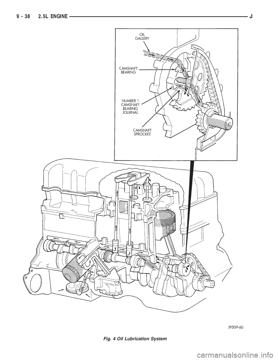
Fig. 4 Oil Lubrication System
9 - 38 2.5L ENGINEJ
Page 1318 of 2158
OIL PUMP
The positive-displacement gear-type oil pump is
driven by the distributor shaft, which is driven by a
gear on the camshaft. Oil is siphoned into the pump
through an inlet tube and strainer assembly that is
pressed into the pump body.
The pump incorporates a nonadjustable pressure
relief valve to limit maximum pressure to 517 kPa
(75 psi). In the relief position, the valve permits oil to
bypass through a passage in the pump body to the
inlet side of the pump.
Oil pump removal or replacement will not affect
the distributor timing because the distributor drive
gear remains in mesh with the camshaft gear.
REMOVAL
(1) Drain the engine oil.
(2) Remove the oil pan.
(3) Remove the pump-to-cylinder block attaching
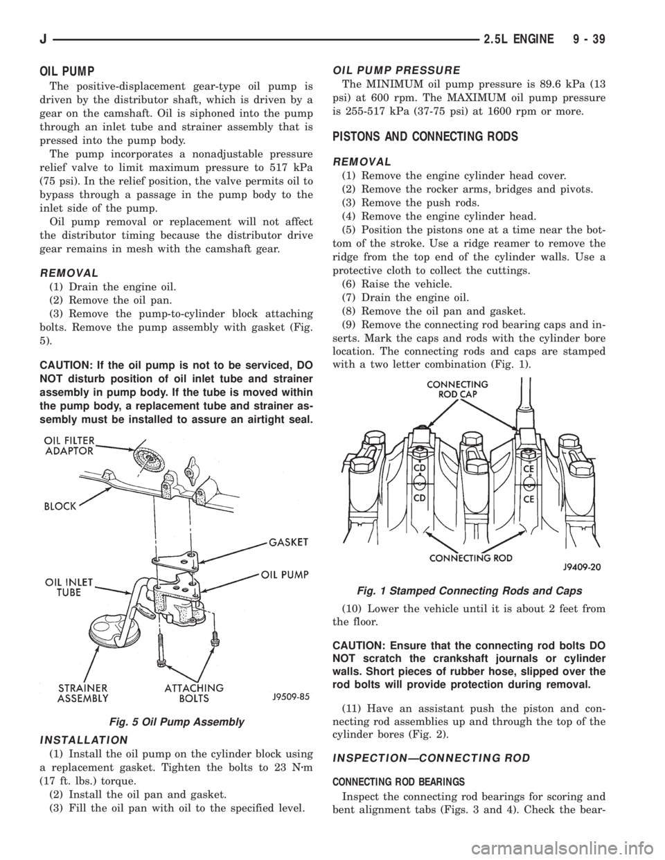
bolts. Remove the pump assembly with gasket (Fig.
5).
CAUTION: If the oil pump is not to be serviced, DO
NOT disturb position of oil inlet tube and strainer
assembly in pump body. If the tube is moved within
the pump body, a replacement tube and strainer as-
sembly must be installed to assure an airtight seal.
INSTALLATION
(1) Install the oil pump on the cylinder block using
a replacement gasket. Tighten the bolts to 23 Nzm
(17 ft. lbs.) torque.
(2) Install the oil pan and gasket.
(3) Fill the oil pan with oil to the specified level.
OIL PUMP PRESSURE
The MINIMUM oil pump pressure is 89.6 kPa (13
psi) at 600 rpm. The MAXIMUM oil pump pressure
is 255-517 kPa (37-75 psi) at 1600 rpm or more.
PISTONS AND CONNECTING RODS
REMOVAL
(1) Remove the engine cylinder head cover.
(2) Remove the rocker arms, bridges and pivots.
(3) Remove the push rods.
(4) Remove the engine cylinder head.
(5) Position the pistons one at a time near the bot-
tom of the stroke. Use a ridge reamer to remove the
ridge from the top end of the cylinder walls. Use a
protective cloth to collect the cuttings.
(6) Raise the vehicle.
(7) Drain the engine oil.
(8) Remove the oil pan and gasket.
(9) Remove the connecting rod bearing caps and in-
serts. Mark the caps and rods with the cylinder bore
location. The connecting rods and caps are stamped
with a two letter combination (Fig. 1).
(10) Lower the vehicle until it is about 2 feet from
the floor.
CAUTION: Ensure that the connecting rod bolts DO
NOT scratch the crankshaft journals or cylinder
walls. Short pieces of rubber hose, slipped over the
rod bolts will provide protection during removal.
(11) Have an assistant push the piston and con-
necting rod assemblies up and through the top of the
cylinder bores (Fig. 2).
INSPECTIONÐCONNECTING ROD
CONNECTING ROD BEARINGS
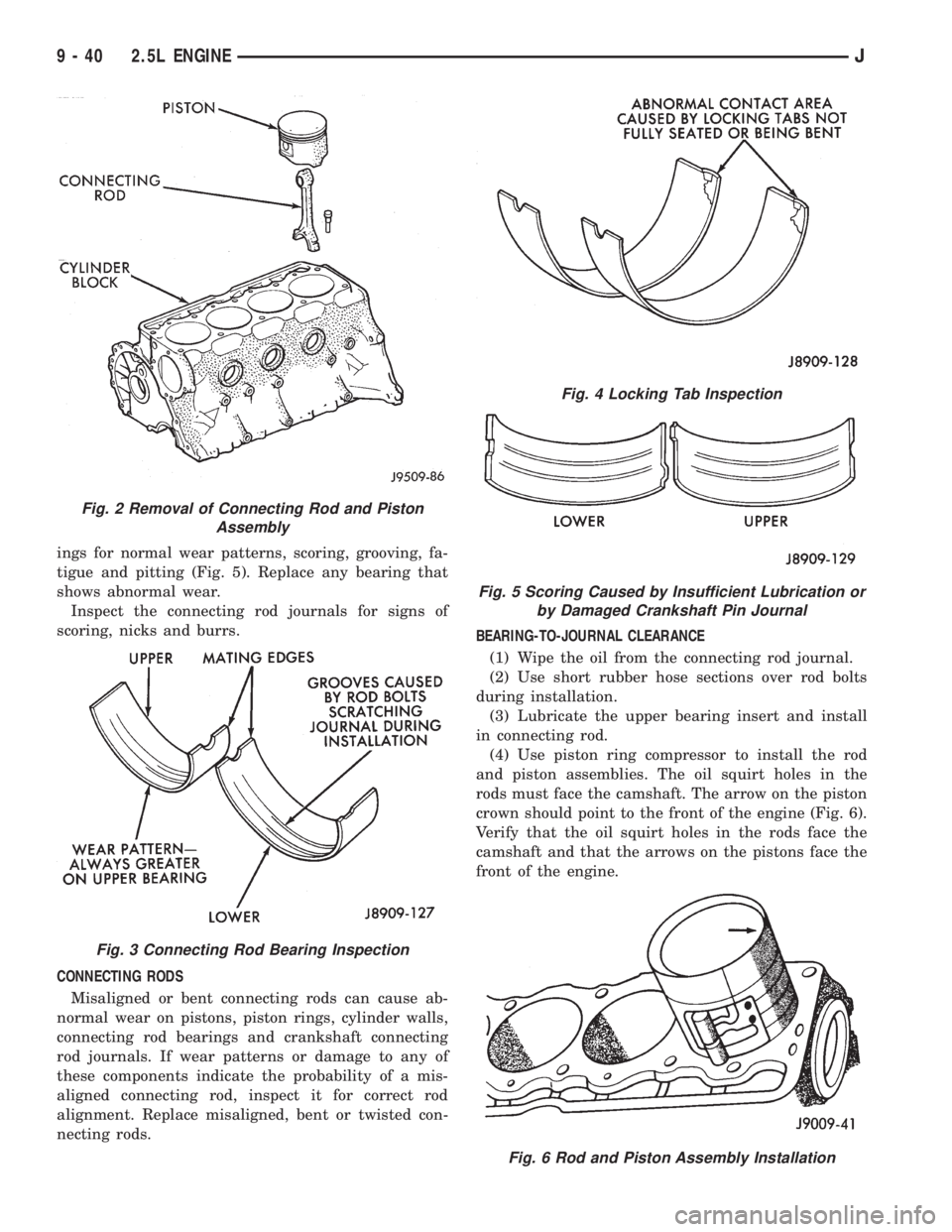
Inspect the connecting rod bearings for scoring and
bent alignment tabs (Figs. 3 and 4). Check the bear-
Fig. 5 Oil Pump Assembly
Fig. 1 Stamped Connecting Rods and Caps
J2.5L ENGINE 9 - 39
Page 1319 of 2158
ings for normal wear patterns, scoring, grooving, fa-
tigue and pitting (Fig. 5). Replace any bearing that
shows abnormal wear.
Inspect the connecting rod journals for signs of
scoring, nicks and burrs.
CONNECTING RODS
Misaligned or bent connecting rods can cause ab-
normal wear on pistons, piston rings, cylinder walls,
connecting rod bearings and crankshaft connecting
rod journals. If wear patterns or damage to any of
these components indicate the probability of a mis-
aligned connecting rod, inspect it for correct rod
alignment. Replace misaligned, bent or twisted con-
necting rods.BEARING-TO-JOURNAL CLEARANCE
(1) Wipe the oil from the connecting rod journal.
(2) Use short rubber hose sections over rod bolts
during installation.
(3) Lubricate the upper bearing insert and install
in connecting rod.
(4) Use piston ring compressor to install the rod
and piston assemblies. The oil squirt holes in the
rods must face the camshaft. The arrow on the piston
crown should point to the front of the engine (Fig. 6).
Verify that the oil squirt holes in the rods face the
camshaft and that the arrows on the pistons face the
front of the engine.
Fig. 2 Removal of Connecting Rod and Piston
Assembly
Fig. 3 Connecting Rod Bearing Inspection
Fig. 4 Locking Tab Inspection
Fig. 5 Scoring Caused by Insufficient Lubrication or
by Damaged Crankshaft Pin Journal
Fig. 6 Rod and Piston Assembly Installation
9 - 40 2.5L ENGINEJ
Page 1320 of 2158
(5) Install the lower bearing insert in the bearing
cap. The lower insert must be dry. Place strip of Plas-
tigage across full width of the lower insert at the cen-
ter of bearing cap. Plastigage must not crumble in
use. If brittle, obtain fresh stock.
(6) Install bearing cap and connecting rod on the
journal and tighten nuts to 45 Nzm (33 ft. lbs.)
torque. DO NOT rotate crankshaft. Plastigage will
smear, resulting in inaccurate indication.
(7) Remove the bearing cap and determine amount
of bearing-to-journal clearance by measuring the
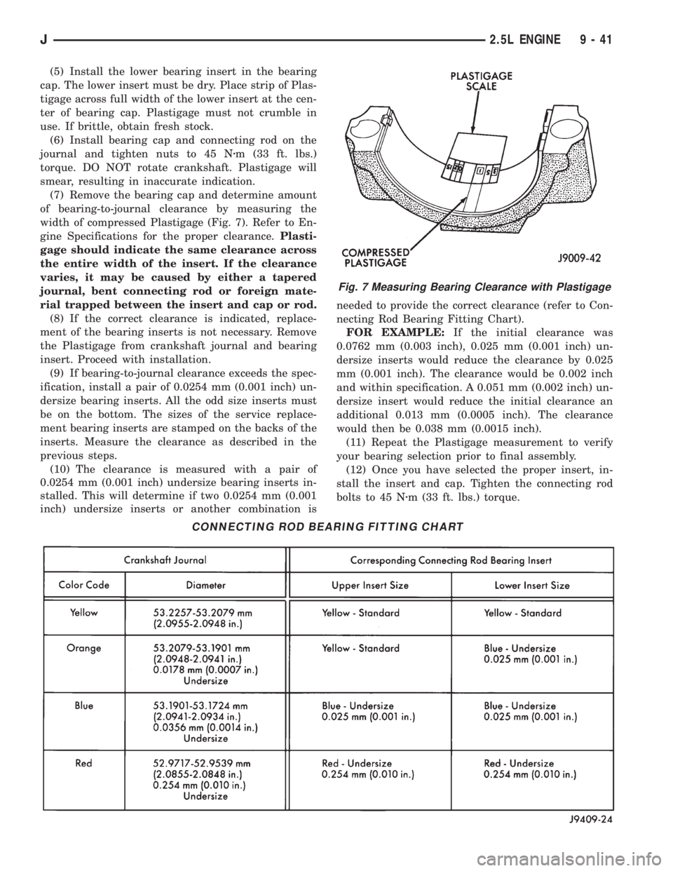
width of compressed Plastigage (Fig. 7). Refer to En-
gine Specifications for the proper clearance.Plasti-
gage should indicate the same clearance across
the entire width of the insert. If the clearance
varies, it may be caused by either a tapered
journal, bent connecting rod or foreign mate-
rial trapped between the insert and cap or rod.
(8) If the correct clearance is indicated, replace-
ment of the bearing inserts is not necessary. Remove
the Plastigage from crankshaft journal and bearing
insert. Proceed with installation.
(9) If bearing-to-journal clearance exceeds the spec-
ification, install a pair of 0.0254 mm (0.001 inch) un-
dersize bearing inserts. All the odd size inserts must
be on the bottom. The sizes of the service replace-
ment bearing inserts are stamped on the backs of the
inserts. Measure the clearance as described in the
previous steps.
(10) The clearance is measured with a pair of
0.0254 mm (0.001 inch) undersize bearing inserts in-
stalled. This will determine if two 0.0254 mm (0.001
inch) undersize inserts or another combination isneeded to provide the correct clearance (refer to Con-
necting Rod Bearing Fitting Chart).
FOR EXAMPLE:If the initial clearance was
0.0762 mm (0.003 inch), 0.025 mm (0.001 inch) un-
dersize inserts would reduce the clearance by 0.025
mm (0.001 inch). The clearance would be 0.002 inch
and within specification. A 0.051 mm (0.002 inch) un-
dersize insert would reduce the initial clearance an
additional 0.013 mm (0.0005 inch). The clearance
would then be 0.038 mm (0.0015 inch).
(11) Repeat the Plastigage measurement to verify
your bearing selection prior to final assembly.
(12) Once you have selected the proper insert, in-
stall the insert and cap. Tighten the connecting rod
bolts to 45 Nzm (33 ft. lbs.) torque.
Fig. 7 Measuring Bearing Clearance with Plastigage
CONNECTING ROD BEARING FITTING CHART
J2.5L ENGINE 9 - 41
Page 1321 of 2158
SIDE CLEARANCE MEASUREMENT
Slide snug-fitting feeler gauge between the connect-
ing rod and crankshaft journal flange. Refer to En-
gine Specifications for the proper clearance. Replace
the connecting rod if the side clearance is not within
specification.
PISTON FITTING
BORE GAUGE METHOD
(1) To correctly select the proper size piston, a cyl-
inder bore gauge, Special Tool 6879 or equivalent, ca-
pable of reading in .00019INCREMENTS with gauge
ring Special Tool 6884 is required. If a bore gauge is
not available, do not use an inside micrometer.
(2) Set the bore gauge to the gauge ring and zero
gauge.
(3) Remove gauge from ring and check cylinder as
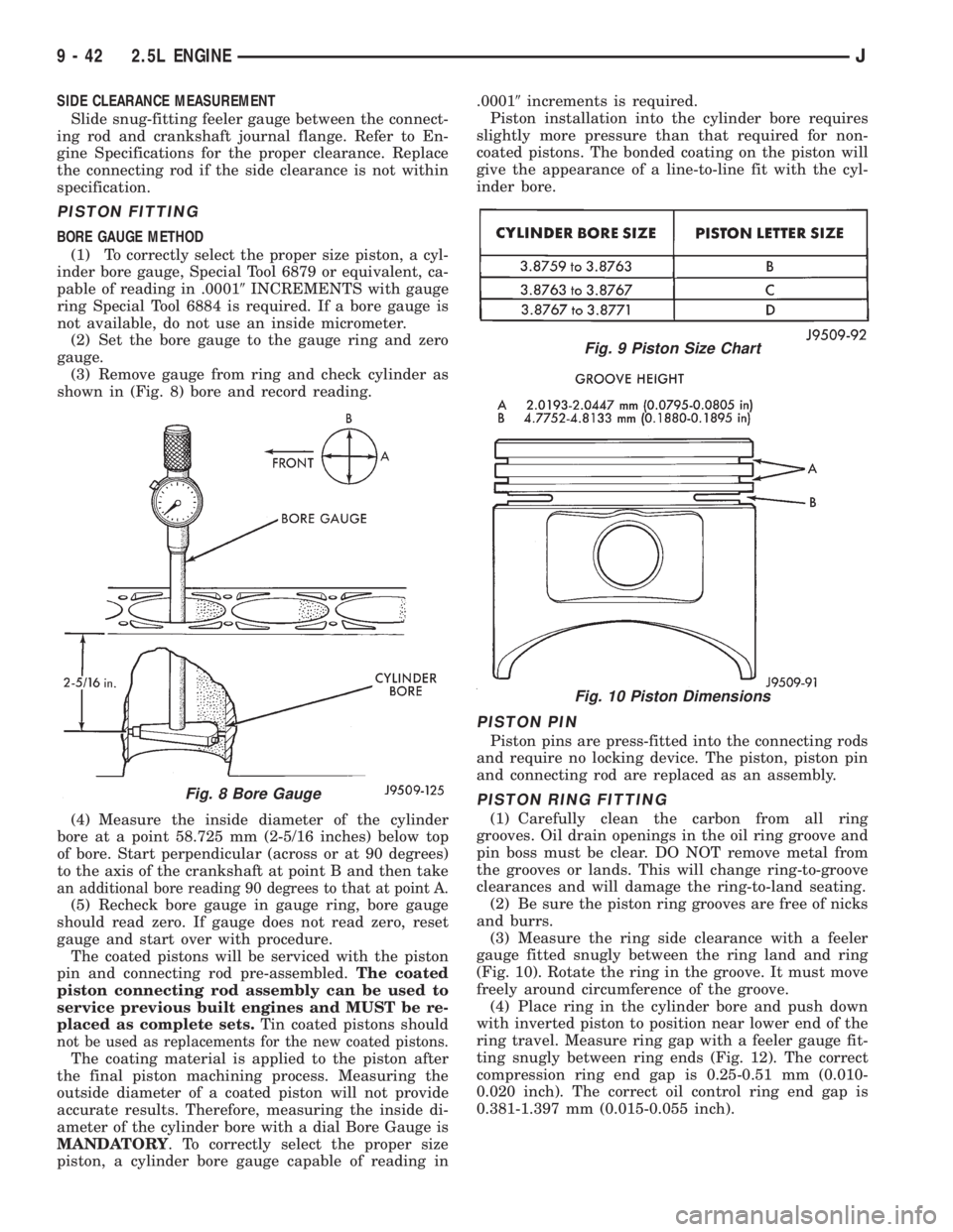
shown in (Fig. 8) bore and record reading.
(4) Measure the inside diameter of the cylinder
bore at a point 58.725 mm (2-5/16 inches) below top
of bore. Start perpendicular (across or at 90 degrees)
to the axis of the crankshaft at point B and then take
an additional bore reading 90 degrees to that at point A.
(5) Recheck bore gauge in gauge ring, bore gauge
should read zero. If gauge does not read zero, reset
gauge and start over with procedure.
The coated pistons will be serviced with the piston
pin and connecting rod pre-assembled.The coated
piston connecting rod assembly can be used to
service previous built engines and MUST be re-
placed as complete sets.Tin coated pistons should
not be used as replacements for the new coated pistons.
The coating material is applied to the piston after
the final piston machining process. Measuring the
outside diameter of a coated piston will not provide
accurate results. Therefore, measuring the inside di-
ameter of the cylinder bore with a dial Bore Gauge is
MANDATORY. To correctly select the proper size
piston, a cylinder bore gauge capable of reading in.00019increments is required.
Piston installation into the cylinder bore requires
slightly more pressure than that required for non-
coated pistons. The bonded coating on the piston will
give the appearance of a line-to-line fit with the cyl-
inder bore.
PISTON PIN
Piston pins are press-fitted into the connecting rods
and require no locking device. The piston, piston pin
and connecting rod are replaced as an assembly.
PISTON RING FITTING
(1) Carefully clean the carbon from all ring
grooves. Oil drain openings in the oil ring groove and
pin boss must be clear. DO NOT remove metal from
the grooves or lands. This will change ring-to-groove
clearances and will damage the ring-to-land seating.
(2) Be sure the piston ring grooves are free of nicks
and burrs.
(3) Measure the ring side clearance with a feeler
gauge fitted snugly between the ring land and ring
(Fig. 10). Rotate the ring in the groove. It must move
freely around circumference of the groove.
(4) Place ring in the cylinder bore and push down
with inverted piston to position near lower end of the
ring travel. Measure ring gap with a feeler gauge fit-
ting snugly between ring ends (Fig. 12). The correct
compression ring end gap is 0.25-0.51 mm (0.010-
0.020 inch). The correct oil control ring end gap is
0.381-1.397 mm (0.015-0.055 inch).
Fig. 8 Bore Gauge
Fig. 9 Piston Size Chart
Fig. 10 Piston Dimensions
9 - 42 2.5L ENGINEJ
Page 1322 of 2158
(5) Install the oil control rings according to instruc-
tions in the package. It is not necessary to use a tool
to install the upper and lower rails. Insert oil rail
spacer first, then side rails.
(6) The two compression rings are different and
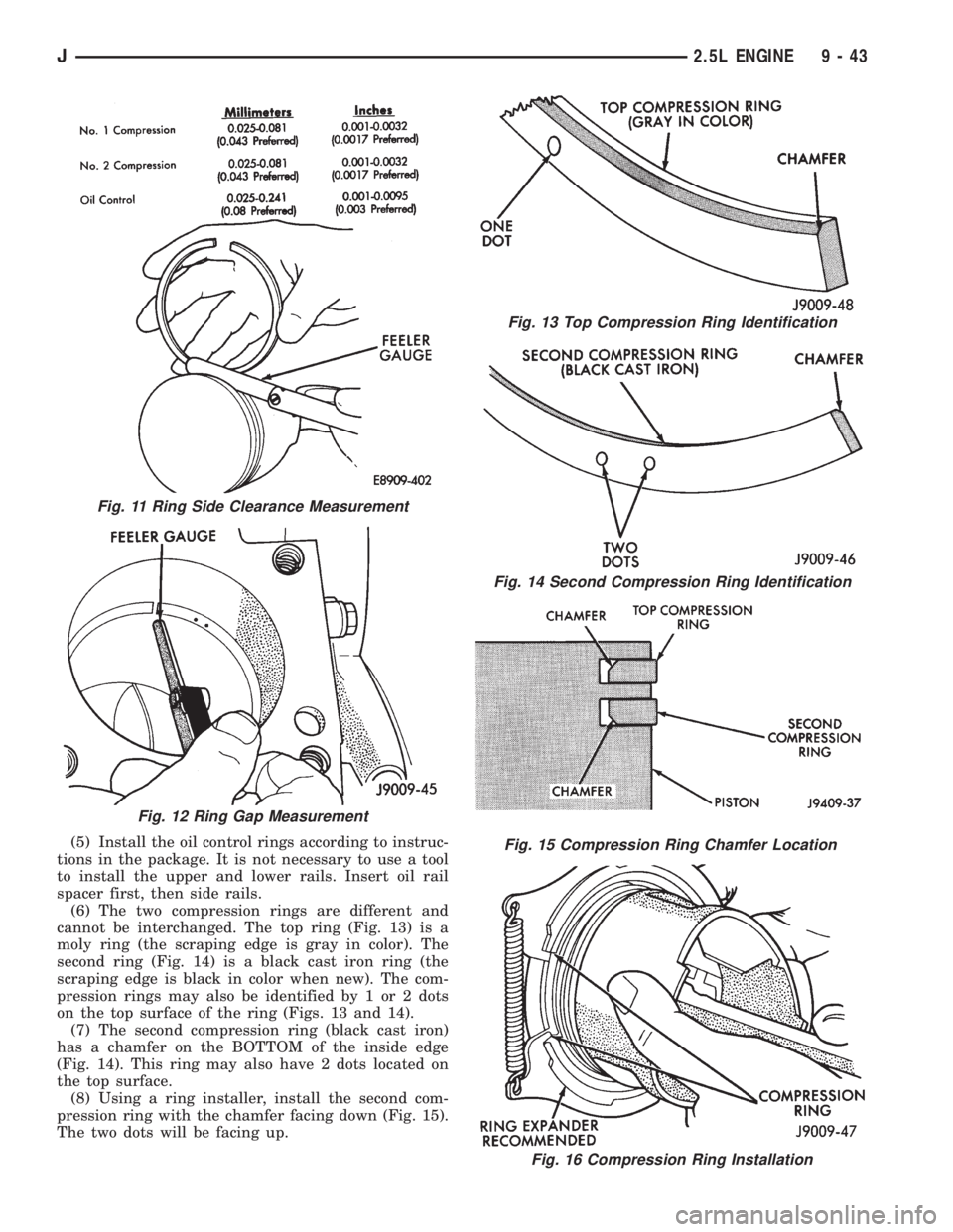
cannot be interchanged. The top ring (Fig. 13) is a
moly ring (the scraping edge is gray in color). The
second ring (Fig. 14) is a black cast iron ring (the
scraping edge is black in color when new). The com-
pression rings may also be identified by 1 or 2 dots
on the top surface of the ring (Figs. 13 and 14).
(7) The second compression ring (black cast iron)
has a chamfer on the BOTTOM of the inside edge
(Fig. 14). This ring may also have 2 dots located on
the top surface.
(8) Using a ring installer, install the second com-
pression ring with the chamfer facing down (Fig. 15).
The two dots will be facing up.
Fig. 16 Compression Ring Installation
Fig. 13 Top Compression Ring Identification
Fig. 14 Second Compression Ring Identification
Fig. 15 Compression Ring Chamfer Location
Fig. 11 Ring Side Clearance Measurement
Fig. 12 Ring Gap Measurement
J2.5L ENGINE 9 - 43
Page 1323 of 2158
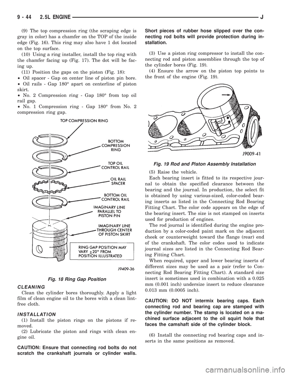
(9) The top compression ring (the scraping edge is
gray in color) has a chamfer on the TOP of the inside
edge (Fig. 16). This ring may also have 1 dot located
on the top surface.
(10) Using a ring installer, install the top ring with
the chamfer facing up (Fig. 17). The dot will be fac-
ing up.
(11) Position the gaps on the piston (Fig. 18):
²Oil spacer - Gap on center line of piston pin bore.
²Oil rails - Gap 180É apart on centerline of piston
skirt.
²No. 2 Compression ring - Gap 180É from top oil
rail gap.
²No. 1 Compression ring - Gap 180É from No. 2
compression ring gap.
CLEANING
Clean the cylinder bores thoroughly. Apply a light
film of clean engine oil to the bores with a clean lint-
free cloth.
INSTALLATION
(1) Install the piston rings on the pistons if re-
moved.
(2) Lubricate the piston and rings with clean en-
gine oil.
CAUTION: Ensure that connecting rod bolts do not
scratch the crankshaft journals or cylinder walls.Short pieces of rubber hose slipped over the con-
necting rod bolts will provide protection during in-
stallation.
(3) Use a piston ring compressor to install the con-
necting rod and piston assemblies through the top of
the cylinder bores (Fig. 19).
(4) Ensure the arrow on the piston top points to
the front of the engine (Fig. 19).
(5) Raise the vehicle.
Each bearing insert is fitted to its respective jour-
nal to obtain the specified clearance between the
bearing and the journal. In production, the select fit
is obtained by using various-sized, color-coded bear-
ing inserts as listed in the Connecting Rod Bearing
Fitting Chart. The color code appears on the edge of
the bearing insert. The size is not stamped on inserts
used for production of engines.
The rod journal is identified during the engine pro-
duction by a color-coded paint mark on the adjacent
cheek or counterweight toward the flange (rear) end
of the crankshaft. The color codes used to indicate
journal sizes are listed in the Connecting Rod Bear-
ing Fitting Chart.
When required, upper and lower bearing inserts of
different sizes may be used as a pair (refer to Con-
necting Rod Bearing Fitting Chart). A standard size
insert is sometimes used in combination with a 0.025
mm (0.001 inch) undersize insert to reduce clearance
0.013 mm (0.0005 inch).
CAUTION: DO NOT intermix bearing caps. Each
connecting rod and bearing cap are stamped with
the cylinder number. The stamp is located on a ma-
chined surface adjacent to the oil squirt hole that
faces the camshaft side of the cylinder block.
(6) Install the connecting rod bearing caps and in-
serts in the same positions as removed.
Fig. 18 Ring Gap Position
Fig. 19 Rod and Piston Assembly Installation
9 - 44 2.5L ENGINEJ
Page 1324 of 2158
CAUTION: Verify that the oil squirt holes in the rods
face the camshaft and that the arrows on the pis-
tons face the front of the engine.
(7) Install the oil pan and gaskets as outlined in
the installation procedure.
(8) Lower the vehicle.
(9) Install the engine cylinder head, push rods,
rocker arms, bridges, pivots and engine cylinder head
cover.
(10) Fill the crankcase with engine oil.
CRANKSHAFT MAIN BEARINGS
REMOVAL
(1) Disconnect negative cable from battery.
(2) Remove the spark plugs.
(3) Raise the vehicle.
(4) Remove the oil pan and oil pump.
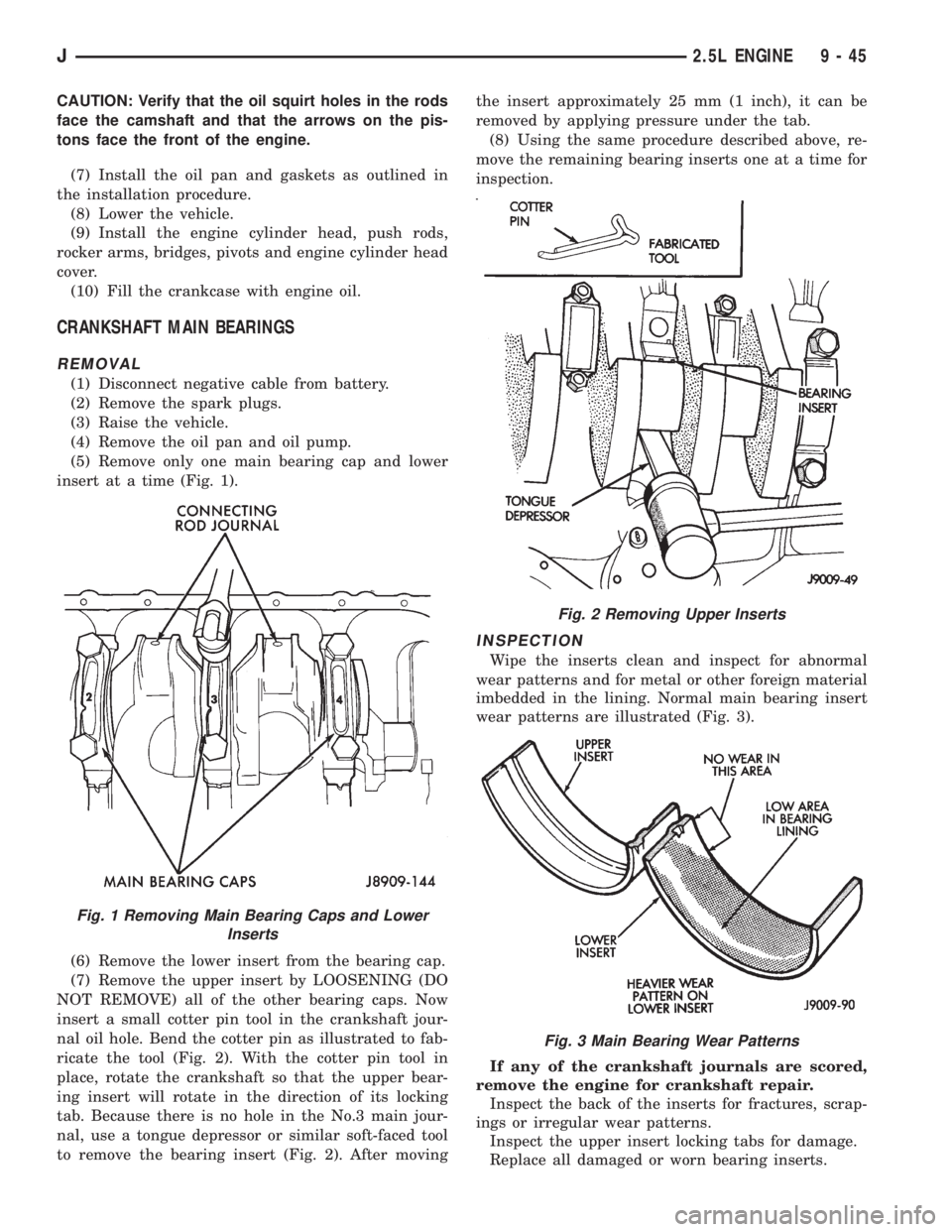
(5) Remove only one main bearing cap and lower
insert at a time (Fig. 1).
(6) Remove the lower insert from the bearing cap.
(7) Remove the upper insert by LOOSENING (DO
NOT REMOVE) all of the other bearing caps. Now
insert a small cotter pin tool in the crankshaft jour-
nal oil hole. Bend the cotter pin as illustrated to fab-
ricate the tool (Fig. 2). With the cotter pin tool in
place, rotate the crankshaft so that the upper bear-
ing insert will rotate in the direction of its locking
tab. Because there is no hole in the No.3 main jour-
nal, use a tongue depressor or similar soft-faced tool
to remove the bearing insert (Fig. 2). After movingthe insert approximately 25 mm (1 inch), it can be
removed by applying pressure under the tab.
(8) Using the same procedure described above, re-
move the remaining bearing inserts one at a time for
inspection.
INSPECTION
Wipe the inserts clean and inspect for abnormal
wear patterns and for metal or other foreign material
imbedded in the lining. Normal main bearing insert
wear patterns are illustrated (Fig. 3).
If any of the crankshaft journals are scored,
remove the engine for crankshaft repair.
Inspect the back of the inserts for fractures, scrap-
ings or irregular wear patterns.
Inspect the upper insert locking tabs for damage.
Replace all damaged or worn bearing inserts.
Fig. 1 Removing Main Bearing Caps and Lower
Inserts
Fig. 2 Removing Upper Inserts
Fig. 3 Main Bearing Wear Patterns
J2.5L ENGINE 9 - 45
Page 1325 of 2158
FITTING (CRANKSHAFT INSTALLED)
The main bearing caps, numbered (front to rear)
from 1 through 5 have an arrow to indicate the for-
ward position. The upper main bearing inserts are
grooved to provide oil channels while the lower in-
serts are smooth.
Each bearing insert pair is selectively fitted to its
respective journal to obtain the specified operating
clearance. In production, the select fit is obtained by
using various-sized color-coded bearing insert pairs
as listed in the Main Bearing Fitting Chart. The
bearing color code appears on the edge of the insert.
The size is not stamped on bearing inserts used
for engine production.
The main bearing journal size (diameter) is identi-
fied by a color-coded paint mark on the adjacent
cheek. The rear main journal, is identified by a color-
coded paint mark on the crankshaft rear flange.
When required, upper and lower bearing inserts of
different sizes may be used as a pair. A standard size
insert is sometimes used in combination with a 0.025
mm (0.001 inch) undersize insert to reduce the clear-
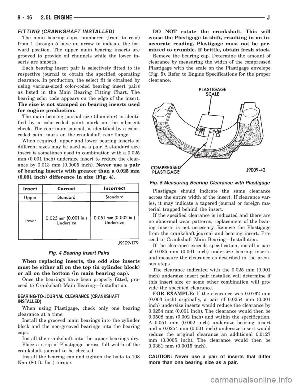
ance by 0.013 mm (0.0005 inch).Never use a pair
of bearing inserts with greater than a 0.025 mm
(0.001 inch) difference in size (Fig. 4).
When replacing inserts, the odd size inserts
must be either all on the top (in cylinder block)
or all on the bottom (in main bearing cap).
Once the bearings have been properly fitted, pro-
ceed to Crankshaft Main BearingÐInstallation.
BEARING-TO-JOURNAL CLEARANCE (CRANKSHAFT
INSTALLED)
When using Plastigage, check only one bearing
clearance at a time.
Install the grooved main bearings into the cylinder
block and the non-grooved bearings into the bearing
caps.
Install the crankshaft into the upper bearings dry.
Place a strip of Plastigage across full width of the
crankshaft journal to be checked.
Install the bearing cap and tighten the bolts to 108
Nzm (80 ft. lbs.) torque.DO NOT rotate the crankshaft. This will
cause the Plastigage to shift, resulting in an in-
accurate reading. Plastigage must not be per-
mitted to crumble. If brittle, obtain fresh stock.
Remove the bearing cap. Determine the amount of
clearance by measuring the width of the compressed
Plastigage with the scale on the Plastigage envelope
(Fig. 5). Refer to Engine Specifications for the proper
clearance.
Plastigage should indicate the same clearance
across the entire width of the insert. If clearance var-
ies, it may indicate a tapered journal or foreign ma-
terial trapped behind the insert.
If the specified clearance is indicated and there are
no abnormal wear patterns, replacement of the bear-
ing inserts is not necessary. Remove the Plastigage
from the crankshaft journal and bearing insert. Pro-
ceed to Crankshaft Main BearingÐInstallation.
If the clearance exceeds specification, install a pair
of 0.025 mm (0.001 inch) undersize bearing inserts
and measure the clearance as described in the previ-
ous steps.
The clearance indicated with the 0.025 mm (0.001
inch) undersize insert pair installed will determine if
this insert size or some other combination will pro-
vide the specified clearance.
FOR EXAMPLE:If the clearance was 0.0762 mm
(0.003 inch) originally, a pair of 0.0254 mm (0.001
inch) undersize inserts would reduce the clearance by
0.0254 mm (0.001 inch). The clearance would then be
0.0508 mm (0.002 inch) and within the specification.
A 0.051 mm (0.002 inch) undersize bearing insert
and a 0.0254 mm (0.001 inch) undersize insert would
reduce the original clearance an additional 0.0127
mm (0.0005 inch). The clearance would then be
0.0381 mm (0.0015 inch).
CAUTION: Never use a pair of inserts that differ
more than one bearing size as a pair.
Fig. 4 Bearing Insert Pairs
Fig. 5 Measuring Bearing Clearance with Plastigage
9 - 46 2.5L ENGINEJ