KIA Amanti 2008 1.G Owner's Manual
Manufacturer: KIA, Model Year: 2008, Model line: Amanti, Model: KIA Amanti 2008 1.GPages: 283, PDF Size: 20.47 MB
Page 231 of 283
In case of an emergency
186
The compact spare should be inflat-
ed to 420 kPa (60 psi).
✽NOTICE
Check the inflation pressure after
installing the spare tire. Adjust it to
the specified pressure, as necessary.
When using a compact spare tire,
observe the following precautions:
• Under no circumstances should
you exceed 80 km/h (50 mph); a
higher speed could damage the
tire.
• Ensure that you drive slowly enough for the road conditions to
avoid all hazards. Any road hazard,
such as a pothole or debris, could
seriously damage the compact
spare.
• Any continuous road use of this tire could result in tire failure, loss of
vehicle control, and possible per-
sonal injury.
• Do not exceed the vehicle’s maxi- mum load rating or the load-carry-
ing capacity shown on the sidewall
of the compact spare tire.
• Avoid driving over obstacles. The compact spare tire diameter is
smaller than the diameter of a con-
ventional tire and reduces the
ground clearance approximately
25 mm (1 inch), which could result
in damage to the vehicle. • Do not take the vehicle through an
automatic car wash with a compact
spare.
• Do not use tire chains on this tire. Because of the smaller size, a tire
chain will not fit properly. This could
damage the vehicle and result in
loss of the chain.
• This tire should not be installed on the front axle if the vehicle must be
driven in snow or on ice.
• Do not use the compact spare tire on any other vehicle because this
tire has been designed especially
for your vehicle.
• The compact spare tire’s tread life is shorter than a regular tire.
Inspect your compact spare tire
regularly and replace worn com-
pact spare tires with the same size
and design, mounted on the same
wheel.
WARNING - Compact spare
This spare tire should be used
only for VERY short distances.
Compact spares should NEVER
be us ed for long drives or
extended distances.
Page 232 of 283
619
In case of an emergency
Changing tires
Jacking instructions
The jack is provided for emergency
tire changing only.
Follow jacking instructions to reduce
the possibility of personal injury.
Tire replacement
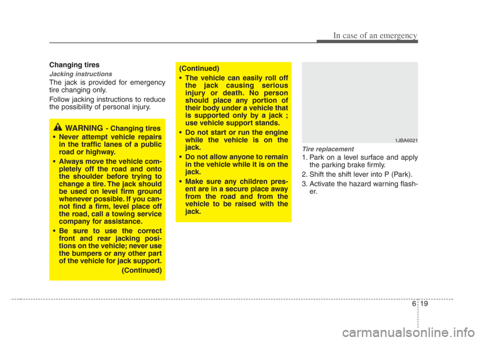
1. Park on a level surface and apply
the parking brake firmly.
2. Shift the shift lever into P (Park).
3. Activate the hazard warning flash- er.
WARNING- Changing tire s
• Never attempt vehicle repair s
in the traffic lanes of a public
road or highway.
•Alway s move the vehicle com-
pletely off the road and onto
the shoulder before trying to
change a tire. The jack should
be used on level firm ground
whenever possible. If you can-
not find a firm, level place off
the road, call a towing service
company for assistance.
• Be sure to use the correct
front and rear jacking po si-
tions on the vehicle; never use
the bumper s or any other part
of the vehicle for jack support.
(Continued)
(Continued)
• The vehicle can easily roll off the jack caus ing serious
injury or death. No per son
should place any portion of
their body under a vehicle that
is supported only by a jack ;
use vehicle support stands.
• Do not start or run the engine while the vehicle i s on the
jack.
• Do not allow anyone to remain in the vehicle while it i s on the
jack.
• Make sure any children pres-
ent are in a secure place away
from the road and from the
vehicle to be rai sed with the
jack.
1JBA6021
Page 233 of 283
In case of an emergency
206
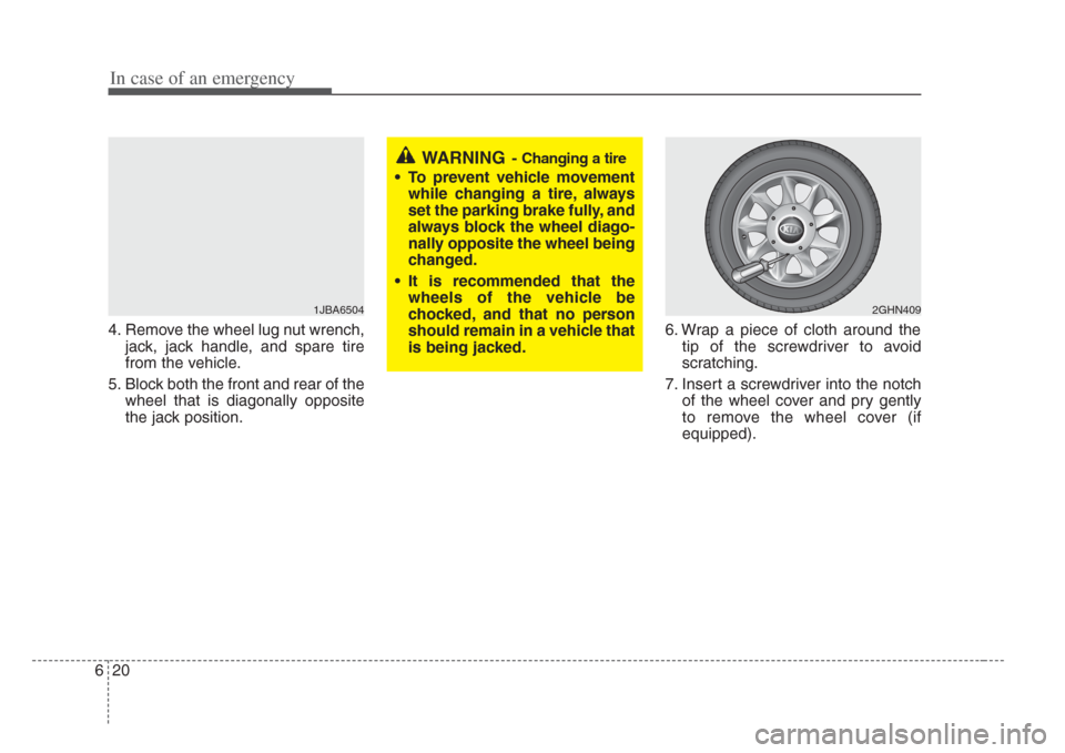
4. Remove the wheel lug nut wrench,jack, jack handle, and spare tire
from the vehicle.
5. Block both the front and rear of the wheel that is diagonally opposite
the jack position. 6. Wrap a piece of cloth around the
tip of the screwdriver to avoid
scratching.
7. Insert a screwdriver into the notch of the wheel cover and pry gently
to remove the wheel cover (if
equipped).
WARNING-Changing a tire
• To prevent vehicle movementwhile changing a tire, alway s
set the parking brake fully, and
always block the wheel diago-
nally opposite the wheel being
changed.
• It is recommended that the wheels of the vehicle be
chocked, and that no per son
should remain in a vehicle that
is being jacked.
1JBA65042GHN409
Page 234 of 283
621
In case of an emergency
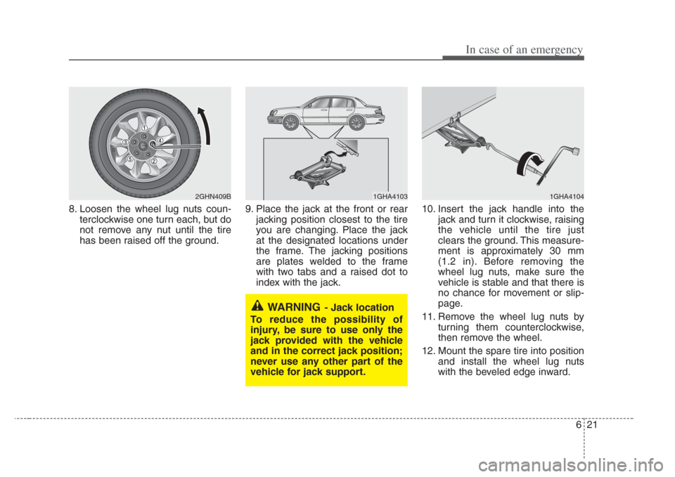
8. Loosen the wheel lug nuts coun-terclockwise one turn each, but do
not remove any nut until the tire
has been raised off the ground. 9. Place the jack at the front or rear
jacking position closest to the tire
you are changing. Place the jack
at the designated locations under
the frame. The jacking positions
are plates welded to the frame
with two tabs and a raised dot to
index with the jack. 10. Insert the jack handle into the
jack and turn it clockwise, raising
the vehicle until the tire just
clears the ground. This measure-
ment is approximately 30 mm
(1.2 in). Before removing the
wheel lug nuts, make sure the
vehicle is stable and that there is
no chance for movement or slip-
page.
11. Remove the wheel lug nuts by turning them counterclockwise,
then remove the wheel.
12. Mount the spare tire into position and install the wheel lug nuts
with the beveled edge inward.
WARNING- Jack location
To reduce the possibility of
injury, be sure to use only the
jack provided with the vehicle
and in the correct jack position;
never use any other part of the
vehicle for jack support.
1GHA41041GHA41032GHN409B
Page 235 of 283
In case of an emergency
226
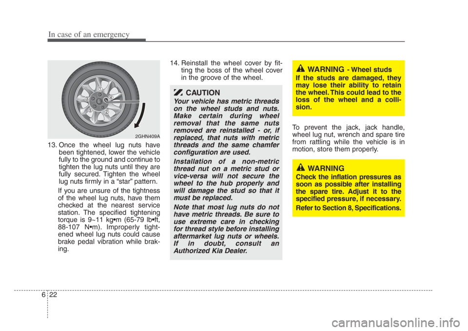
13. Once the wheel lug nuts havebeen tightened, lower the vehicle
fully to the ground and continue to
tighten the lug nuts until they are
fully secured. Tighten the wheel
lug nuts firmly in a “star” pattern.
If you are unsure of the tightness
of the wheel lug nuts, have them
checked at the nearest service
station. The specified tightening
torque is 9~11 kg•m (65-79 lb•ft,
88-107 N•m). Improperly tight-
ened wheel lug nuts could cause
brake pedal vibration while brak-
ing. 14. Reinstall the wheel cover by fit-
ting the boss of the wheel cover
in the groove of the wheel.
To prevent the jack, jack handle,
wheel lug nut, wrench and spare tire
from rattling while the vehicle is in
motion, store them properly.
2GHN409A
CAUTION
Your vehicle has metric threadson the wheel studs and nuts.Make certain during wheelremoval that the s ame nuts
removed are reinstalled - or, if replaced, that nut s with metric
threads and the same chamfer configuration are used.
Ins tallation of a non-metric
thread nut on a metric stud or
vice-ver sa will not secure the
wheel to the hub properly and will damage the stud so that it
mu st be replaced.
Note that most lug nuts do not have metric threads. Be sure to
use extreme care in checking for thread style before in stalling
aftermarket lug nut s or wheels.
If in doubt, cons ult an
Authorized Kia Dealer.
WARNING- Wheel studs
If the studs are damaged, they
may lose their ability to retain
the wheel. Thi s could lead to the
loss of the wheel and a colli-
sion.
WARNING
Check the inflation pressures as
s oon as possible after ins talling
the spare tire. Adjus t it to the
s pecified pre ssure, if necessary.
Refer to Section 8, Specifications .
Page 236 of 283
7
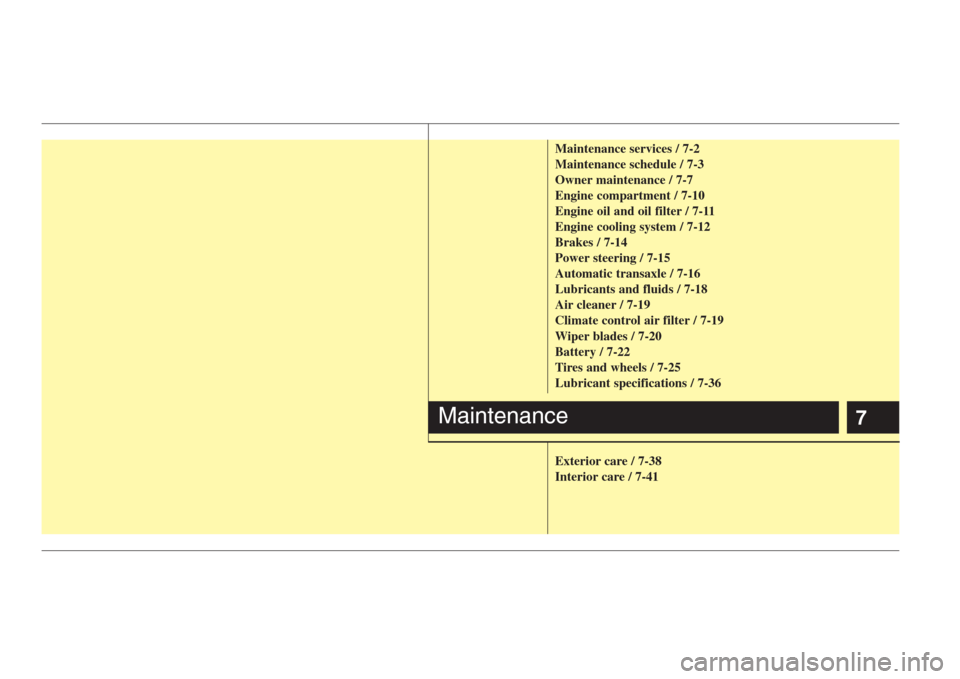
Maintenance services / 7-2
Maintenance schedule / 7-3
Owner maintenance / 7-7
Engine compartment / 7-10
Engine oil and oil filter / 7-11
Engine cooling system / 7-12
Brakes / 7-14
Power steering / 7-15
Automatic transaxle / 7-16
Lubricants and fluids / 7-18
Air cleaner / 7-19
Climate control air filter / 7-19
Wiper blades / 7-20
Battery / 7-22
Tires and wheels / 7-25
Lubricant specifications / 7-36
Exterior care / 7-38
Interior care / 7-41
Maintenance
Page 237 of 283
Maintenance
27
MAINTENANCE SERVICES
You should exercise the utmost care to
prevent damage to your vehicle and
injury to yourself whenever performing
any maintenance or inspection proce-
dures.
Should you have any doubts concerning
the inspection or servicing of your vehi-
cle, we strongly recommend that you
have an Authorized Kia Dealer perform
this work.
An Authorized Kia Dealer has factory-
trained technicians and genuine Kia
parts to service your vehicle properly. For
expert advice and quality service, see an
Authorized Kia Dealer.
Inadequate, incomplete or insufficient
servicing may result in operational prob-
lems with your vehicle that could lead to
vehicle damage, an accident, or person-
al injury.Owner’s responsibility
✽
NOTICE
Maintenance Service and Record
Retention are the owner's responsibility.
You should retain documents that show
proper maintenance has been performed
on your vehicle in accordance with the
scheduled maintenance service charts
shown on the following pages. You need
this information to establish your compli-
ance with the servicing and maintenance
requirements of your Kia warranties.
Detailed warranty information is provided
in your Warranty & Consumer
Information manual. Repairs and adjustments required as a
result of improper maintenance or a lack
of required maintenance are not covered.
We strongly recommend that all vehicle
maintenance be performed by an author-
ized Kia dealer using genuine Kia parts.
Page 238 of 283
73
Maintenance
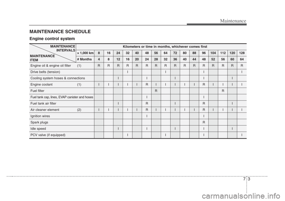
MAINTENANCE SCHEDULE
Kilometers or time in months, whichever come s first
× 1,000 km 8 16 24 32 40 48 56 64 72 80 88 96 104 112 120 128
# Months 4 8 12 16 20 24 28 32 36 40 44 48 52 56 60 64
Engine oil & engine oil filter (1) R R R R R R RRRRRRR RRR
Drive belts (tension) I I I I
Cooling system hoses & connections I I I I I
Engine coolant (1) I I I I I R IIIIIRI III
Fuel filter RR
Fuel tank cap, lines, EVAP canister and hosesII
Fuel tank air filter I R I R I
Air cleaner element (2) I I I I I R IIIIIRI III
Ignition wires I I
Spark plugs R
Idle speed I I I I I
PCV valve (if equipped) I I I I
MAINTENANCE INTERVALS
MAINTENANCE
ITEM
Engine control system
Page 239 of 283
Maintenance
47
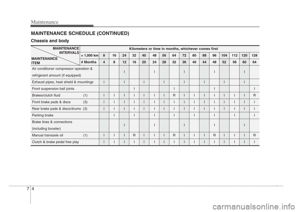
MAINTENANCE SCHEDULE (CONTINUED)
Kilometers or time in months, whichever come s first
× 1,000 km 8 16 24 32 40 48 56 64 72 80 88 96 104 112 120 128
# Months 4 8 12 16 20 24 28 32 36 40 44 48 52 56 60 64
Air conditioner compressor operation & IIIII
refrigerant amount (if equipped)
Exhaust pipes, heat shield & mountings I I IIIIII
Front suspension ball joints I I I I
Brakes/clutch fluid (1) I I I I I I I R IIIII IIR
Front brake pads & discs (3) I I I I I I IIIIIII III
Rear brake pads & discs/drums (3) I I I I I I IIIIIII III
Parking brake I I I IIIII
Brake lines & connections IIIII
(including booster)
Manual transaxle oil (1) I I I R I I I R I I I R I I I R
Clutch & brake pedal free play I I I I I I IIIIIII III
MAINTENANCE
INTERVALS
MAINTENANCE
ITEM
Chassis and body
Page 240 of 283
75
Maintenance
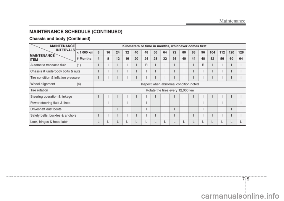
MAINTENANCE SCHEDULE (CONTINUED)
Kilometers or time in months, whichever come s first
× 1,000 km 8 16 24 32 40 48 56 64 72 80 88 96 104 112 120 128
# Months 4 8 12 16 20 24 28 32 36 40 44 48 52 56 60 64
Automatic transaxle fluid (1) I I I I I R IIIIIRI III
Chassis & underbody bolts & nuts I I I I I I IIIIIII III
Tire condition & inflation pressure I I I I I I IIIIIII III
Wheel alignment (4)
Tire rotation
Steering operation & linkage I I I I I I IIIIIII III
Power steering fluid & lines I I I IIIII
Driveshaft dust boots I I I I I
Safety belts, buckles & anchors I I I I I I IIIIIII III
Lock, hinges & hood latch L L L L L L LLLLLLL LLL
MAINTENANCE
INTERVALS
MAINTENANCE
ITEM
Inspect when abnormal condition noted
Rotate the tires every 12,000 km
Chassis and body (Continued)