display KIA CADENZA 2020 Repair Manual
[x] Cancel search | Manufacturer: KIA, Model Year: 2020, Model line: CADENZA, Model: KIA CADENZA 2020Pages: 560, PDF Size: 11.37 MB
Page 392 of 560
5139
Driving your vehicle
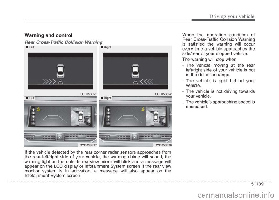
When the operation condition of
Rear Cross-Traffic Collision Warning
is satisfied the warning will occur
every time a vehicle approaches the
side/rear of your stopped vehicle.
The warning will stop when:
- The vehicle moving at the rear
left/right side of your vehicle is not
in the detection range.
- The vehicle is right behind your
vehicle.
- The vehicle is not driving towards
your vehicle.
- The vehicle’s approaching speed is
decreased.
OJF058351
OYG059297
OJF058352
OYG059298
■ Left
■ Left
■ Right
■ Right
Warning and control
Rear Cross-Traffic Collision Warning
If the vehicle detected by the rear corner radar sensors approaches from
the rear left/right side of your vehicle, the warning chime will sound, the
warning light on the outside rearview mirror will blink and a message will
appear on the LCD display or Infotainment System screen If the rear view
monitor system is in activation, a message will also appear on the
Infotainment System screen.
Page 394 of 560
5141
Driving your vehicle
The brake control may not operate
properly according to the status of
the ESC (Electronic Stability
Control). The same warning mes-
sage is displayed on the instrument
cluster for this case also.
- When the ESC (Electronic Stability
Control) warning light is on.
- When the ESC (Electronic Stability
Control) is engaged in a different
function.
When the operation condition of
Rear Cross-Traffic Collision
Warning is satisfied, the warning
will occur every time a vehicle
approaches the side or rear of your
stopped (0 mph (0 km/h) vehicle
speed) vehicle.
The driver should always exercise
extreme caution while operating
the vehicle, whether or not the
warning light on the outside
rearview mirror illuminates or there
is a warning alarm.
Playing the vehicle audio system at
high volume may prevent you from
hearing the system's warning
sounds.CAUTION
The system's warning or
brake may not operate proper-
ly if the left/right of your vehi-
cle's rear bumper is obscured
by a vehicle or obstacle.
The warning of Rear Cross-
Traffic Collision Warning may
not sound while other sys-
tem's warning sounds.
If any other warning sound
such as seat belt warning
chime is already generated,
Rear Cross-Traffic Collision
Warning may not sound.
WARNING
Drive safely even though the
vehicle is equipped with a
Rear Cross-Traffic Collision
Warning and Rear Cross-
Traffic Collision-Avoidance
Assist. Do not solely rely on
the system but check your
surrounding when backing
the vehicle up.
The driver is responsible for
accurate brake control.
Always exercise extreme cau-
tion while driving. Rear Cross-
Traffic Collision Warning and
Rear Cross-Traffic Collision-
Avoidance Assist may not
operate properly or unneces-
sarily operate in accordance
with your driving situations.
(Continued)
Page 395 of 560
Driving your vehicle
142 5
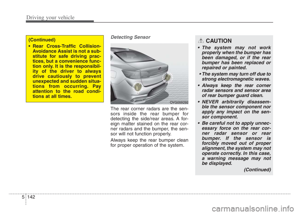
Detecting Sensor
The rear corner radars are the sen-
sors inside the rear bumper for
detecting the side/rear areas. A for-
eign matter stained on the rear cor-
ner radars and the bumper, the sen-
sor will not function properly.
Always keep the rear bumper clean
for proper operation of the system.
(Continued)
Rear Cross-Traffic Collision-
Avoidance Assist is not a sub-
stitute for safe driving prac-
tices, but a convenience func-
tion only. It is the responsibil-
ity of the driver to always
drive cautiously to prevent
unexpected and sudden situa-
tions from occurring. Pay
attention to the road condi-
tions at all times.
OYG059292
CAUTION
The system may not work
properly when the bumper has
been damaged, or if the rear
bumper has been replaced or
repaired or painted.
The system may turn off due to
strong electromagnetic waves.
Always keep the rear corner
radar sensors and sensor area
of rear bumper guard clean.
NEVER arbitrarily disassem-
ble the sensor component nor
apply any impact on the sen-
sor component.
Be careful not to apply unnec-
essary force on the rear cor-
ner radar sensor or rear
bumper. If the sensor is
forcibly moved out of proper
alignment, the system may not
operate correctly. In this case,
a warning message may not
be displayed.
(Continued)
Page 397 of 560

Driving your vehicle
144 5
When BCW canceled warning mes-
sage is displayed in the cluster,
check to make sure that the rear
bumper is free from any dirt or snow
in the areas where the sensor is
located. Remove any dirt, snow, or
foreign material that could interfere
with the radar sensors.
After any dirt or debris is removed,
RCCA system should operate nor-
mally after about 10 minutes of driv-
ing the vehicle.
If the system does not work normally
even though the foreign substance,
trailer or carrier, or other equipment
is removed, have the system
checked by an authorized Kia dealer.Check Blind-Spot Collision Warning
system
If there is a problem with BCW sys-
tem, a warning message will appear.
The system will turn off automatical-
ly. RCCW and RCCA will not operate
also if BCW system turns off due to
malfunction. In this case, have the
system checked by an authorized
Kia dealer.Limitations of the system
The driver must be cautious in the
below situations, because the sys-
tem may not detect other vehicles
or objects in certain circum-
stances.
When a trailer or carrier is
installed.
The vehicle drives in inclement
weather such as heavy rain or
snow.
The rear corner radar sensors are
is polluted with rain, snow, mud,
etc.
The rear bumper where the sensor
is located is covered with a foreign
object such as a bumper sticker, a
bumper guard, a bike rack, etc.
The rear bumper is damaged, or
the sensor is out of the original
default position.
The vehicle height gets lower or
higher due to heavy loading in a
trunk (tailgate), abnormal tire pres-
sure, etc.
OJF058435L
Page 425 of 560
69
What to do in an emergency
TIRE PRESSURE MONITORING SYSTEM (TPMS)
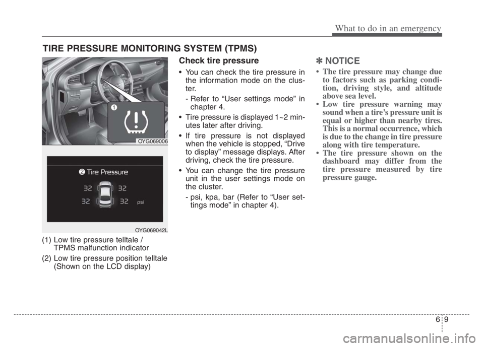
(1) Low tire pressure telltale /
TPMS malfunction indicator
(2) Low tire pressure position telltale
(Shown on the LCD display)
Check tire pressure
You can check the tire pressure in
the information mode on the clus-
ter.
- Refer to “User settings mode” in
chapter 4.
Tire pressure is displayed 1~2 min-
utes later after driving.
If tire pressure is not displayed
when the vehicle is stopped, “Drive
to display” message displays. After
driving, check the tire pressure.
You can change the tire pressure
unit in the user settings mode on
the cluster.
- psi, kpa, bar (Refer to “User set-
tings mode” in chapter 4).
✽ ✽
NOTICE
• The tire pressure may change due
to factors such as parking condi-
tion, driving style, and altitude
above sea level.
• Low tire pressure warning may
sound when a tire’s pressure unit is
equal or higher than nearby tires.
This is a normal occurrence, which
is due to the change in tire pressure
along with tire temperature.
• The tire pressure shown on the
dashboard may differ from the
tire pressure measured by tire
pressure gauge.
OYG069006
OYG069042L
Page 487 of 560

Maintenance
42 7
3. Checking tire life (TIN : Tire
Identification Number)
Any tires that are over 6 years old,
based on the manufacturing date,
(including the spare tire) should be
replaced by new ones. You can find
the manufacturing date on the tire
sidewall (possibly on the inside of the
wheel), displaying the DOT Code.
The DOT Code is a series of num-
bers on a tire consisting of numbers
and English letters. The manufactur-
ing date is designated by the last four
digits (characters) of the DOT code.
DOT : XXXX XXXX OOOO
The front part of the DOT means a
plant code number, tire size and
tread pattern and the last four num-
bers indicate week and year manu-
factured.
For example:
DOT XXXX XXXX 1620 represents
that the tire was produced in the 16th
week of 2020.
4. Tire ply composition and mate-
rial
The number of layers or plies of rub-
ber-coated fabric in the tire. Tire
manufacturers also must indicate the
materials in the tire, which include
steel, nylon, polyester, and others.
The letter "R" means radial ply con-
struction; the letter "D" means diago-
nal or bias ply construction; and the
letter "B" means belted-bias ply con-
struction.
5. Maximum permissible inflation
pressure
This number is the greatest amount of
air pressure that should be put in the
tire. Do not exceed the maximum per-
missible inflation pressure. Refer to
the Tire and Loading Information label
for recommended inflation pressure.
6. Maximum load rating
This number indicates the maximum
load in kilograms and pounds that can
be carried by the tire. When replacing
the tires on the vehicle, always use a
tire that has the same load rating as
the factory installed tire.
7. Uniform tire quality grading
Quality grades can be found where
applicable on the tire sidewall
between tread shoulder and maxi-
mum section width.
For example:
TREADWEAR 440
TRACTION A
TEMPERATURE A
WARNING - Tire age
Replace tires within the recom-
mended time frame. Failure to
replace tires as recommended
can result in sudden tire failure,
which could lead to a loss of
control and an accident.
Page 496 of 560
751
Maintenance
✽ ✽
NOTICE
• When replacing fuse, turn the
ignition “OFF” and turn off
switches of all electrical devices
then remove battery (-) terminal.
• The actual fuse/relay panel label
may differ from equipped items.
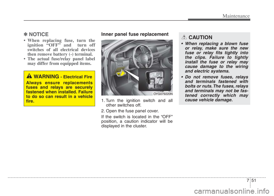
Inner panel fuse replacement
1. Turn the ignition switch and all
other switches off.
2. Open the fuse panel cover.
If the switch is located in the “OFF”
position, a caution indicator will be
displayed in the cluster.
WARNING- Electrical Fire
Always ensure replacements
fuses and relays are securely
fastened when installed. Failure
to do so can result in a vehicle
fire.
CAUTION
When replacing a blown fuse
or relay, make sure the new
fuse or relay fits tightly into
the clips. Failure to tightly
install the fuse or relay may
cause damage to the wiring
and electric systems.
Do not remove fuses, relays
and terminals fastened with
bolts or nuts. The fuses, relays
and terminals may not be fas-
tened correctly which may
cause vehicle damage.
OYG079220N
Page 498 of 560
753
Maintenance
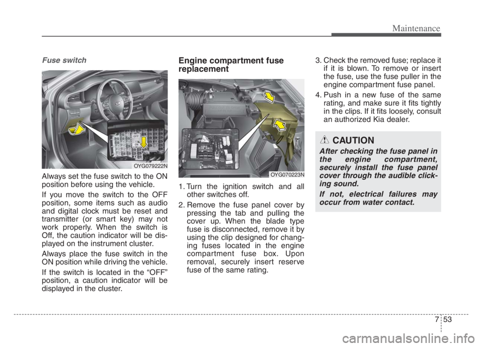
Fuse switch
Always set the fuse switch to the ON
position before using the vehicle.
If you move the switch to the OFF
position, some items such as audio
and digital clock must be reset and
transmitter (or smart key) may not
work properly. When the switch is
Off, the caution indicator will be dis-
played on the instrument cluster.
Always place the fuse switch in the
ON position while driving the vehicle.
If the switch is located in the “OFF”
position, a caution indicator will be
displayed in the cluster.
Engine compartment fuse
replacement
1. Turn the ignition switch and all
other switches off.
2. Remove the fuse panel cover by
pressing the tab and pulling the
cover up. When the blade type
fuse is disconnected, remove it by
using the clip designed for chang-
ing fuses located in the engine
compartment fuse box. Upon
removal, securely insert reserve
fuse of the same rating.3. Check the removed fuse; replace it
if it is blown. To remove or insert
the fuse, use the fuse puller in the
engine compartment fuse panel.
4. Push in a new fuse of the same
rating, and make sure it fits tightly
in the clips. If it fits loosely, consult
an authorized Kia dealer.
CAUTION
After checking the fuse panel in
the engine compartment,
securely install the fuse panel
cover through the audible click-
ing sound.
If not, electrical failures may
occur from water contact.
OYG079222N
OYG070223N
Page 502 of 560
757
Maintenance
Fuse NameFuse ratingCircuit Protected
MODULE 710ADriver Door Module, Passenger Door Module
MODULE 310AStop Lamp Switch, BCM (Body Control Module), Sports Mode Switch
MODULE 510AConsole Switch, Blind-Spot Collision Warning Unit Left Handle side/Right Handle side, BCM (Body Control
Module), Crash Pad Switch, Fuel Filler & Trunk Open Switch, Lane Keeping Assist Unit (Line), Steering Tilt
& Telescopic Module, Smart Cruise Control Unit, Parking Collision Avoidance Assist Unit
IG 125APCB Block (Fuse – TCU 2, ECU 3, ABS 3)
MDPS7.5AMDPS (Motor Driven Power Steering) Unit
MODULE 610A
Air Conditioner Switch, Air Conditioner Control Module, Electro Chromic Mirror, Wireless Charger Unit, Front
Seat Warmer Control Module, Front Air Ventilation Seat Control Module, Rear Seat Warmer Control Module,
Audio/Video & Navigation Head Unit, Audio, Driver Integrated Memory System Module, Automatic
Transmission Shift Lever Indicator
CLUSTER10AInstrument Cluster, Head-Up Display
AIR BAG15ASRS (Supplemental Restraint System) Control Module, Passenger Occupant Detection Sensor
MULTIMEDIA 120AIGPM (Integrated Gateway Power control Module), Audio/Video & Navigation Head Unit, Audio
A/BAG IND7.5AAir Conditioner Switch, Instrument Cluster
MODULE 410ASmart Key Control Module, Immobilizer Module
SPARE 210ASpare
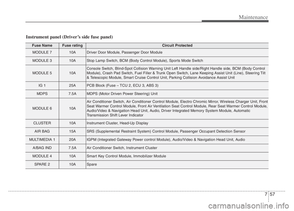
Instrument panel (Driver’s side fuse panel)
Page 503 of 560
Maintenance
58 7
Fuse NameFuse ratingCircuit Protected
A/C7.5AAir Conditioner Switch, Air Conditioner Control Module, Ionizer, Engine Room Junction Block (Blower Relay)
MEMORY 110AHead-Up Display, Instrument Cluster, Blind-Spot Collision Warning Unit Left Handle side/Right Handle side,
Driver Door Module, Power Trunk Module, Passenger Door Module, Air Conditioner Switch, Air Conditioner
Control Module, Security Indicator, BCM (Body Control Module)
MEMORY 215ADriver Door Module
MEMORY 310APassenger Door Module
START7.5ATransmission Range Switch
HEATED
STEERING15ABCM (Body Control Module)
MODULE 97.5ASurround View Monitor Unit, Rear Seat Warmer Control Module, Front Seat Warmer Control Module, Front
Air Ventilation Seat Control Module, Parking Collision Avoidance Assist Unit
WASHER15AMultifunction Switch
INTERIOR
LAMP10AGlove Box Lamp, Passenger Foot Lamp, Driver Foot Lamp, Room Lamp, Front Vanity Lamp Switch Left
Handle side/Right Handle side, Overhead Console Lamp, Trunk Room Lamp, Rear Personal Lamp Left
Handle side/Right Handle side
DOOR LOCK20ADoor Lock/Unlock Relay
S/HEATER (FR)25AFront Seat Warmer Control Module, Front Air Ventilation Seat Control Module
SMART KEY 210AStart/Stop Button Switch
BRAKE SWITCH10AStop Lamp Switch, Immobilizer Module, Smart Key Control Module
AMP30AAMP (Amplifier)