starter KIA CARNIVAL 2007 User Guide
[x] Cancel search | Manufacturer: KIA, Model Year: 2007, Model line: CARNIVAL, Model: KIA CARNIVAL 2007Pages: 1575, PDF Size: 44.86 MB
Page 180 of 1575
2007 > 2.7L V6 GASOLINE >
REMOVAL
STATATER
1. Disconnect the battery negative cable.
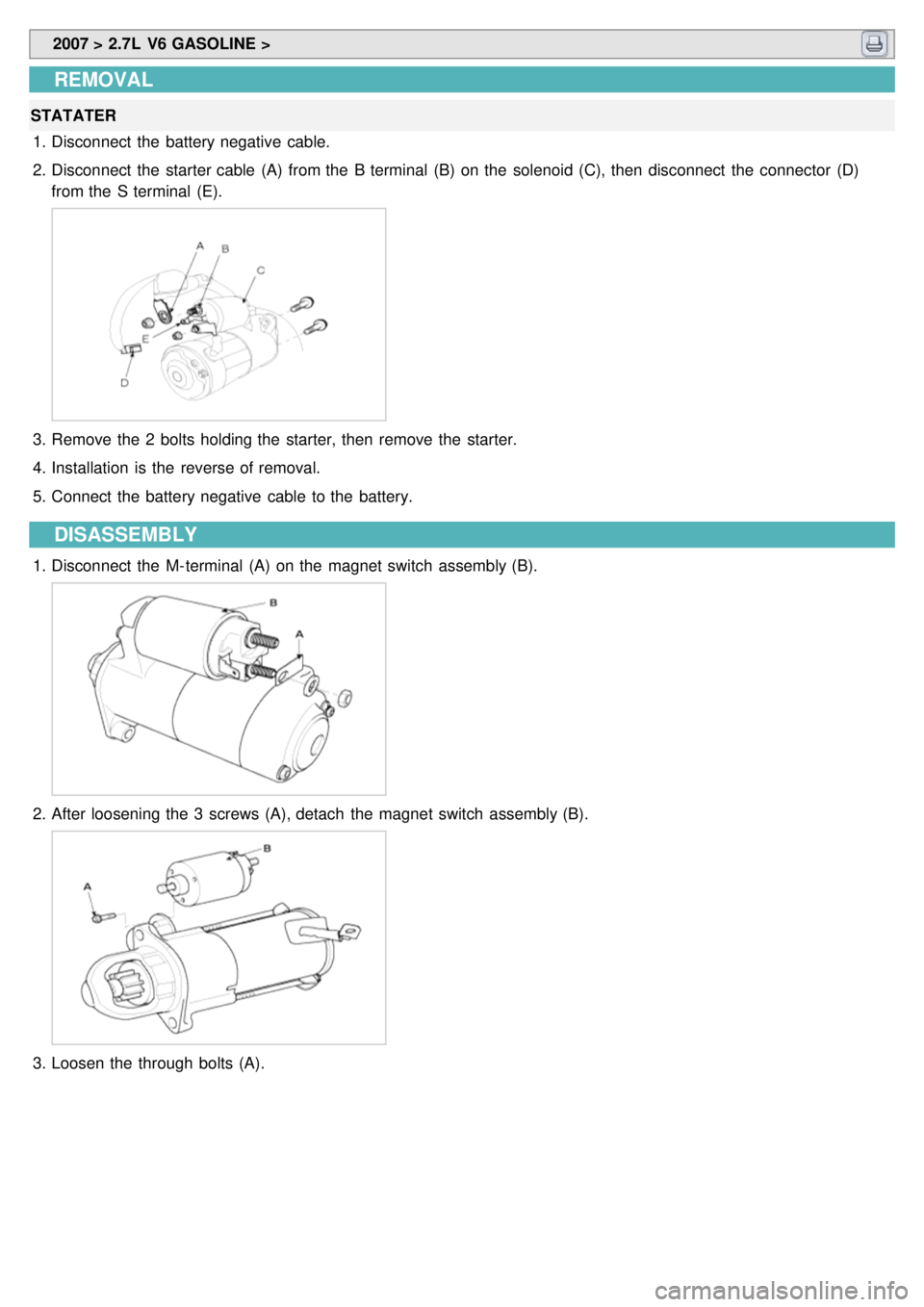
2. Disconnect the starter cable (A) from the B terminal (B) on the solenoid (C), then disconnect the connector (D)
from the S terminal (E).
3.Remove the 2 bolts holding the starter, then remove the starter.
4. Installation is the reverse of removal.
5. Connect the battery negative cable to the battery.
DISASSEMBLY
1.Disconnect the M- terminal (A) on the magnet switch assembly (B).
2.After loosening the 3 screws (A), detach the magnet switch assembly (B).
3.Loosen the through bolts (A).
Page 183 of 1575
INSPECTION
ARMATURE INSPECTION AND TEST1. Remove the starter.
2. Disassemble the starter as shown at the beginning of this procedure.
3. Inspect the armature for wear or damage from contact with the permanent magnet. If there is wear or damage,
replace the armature.
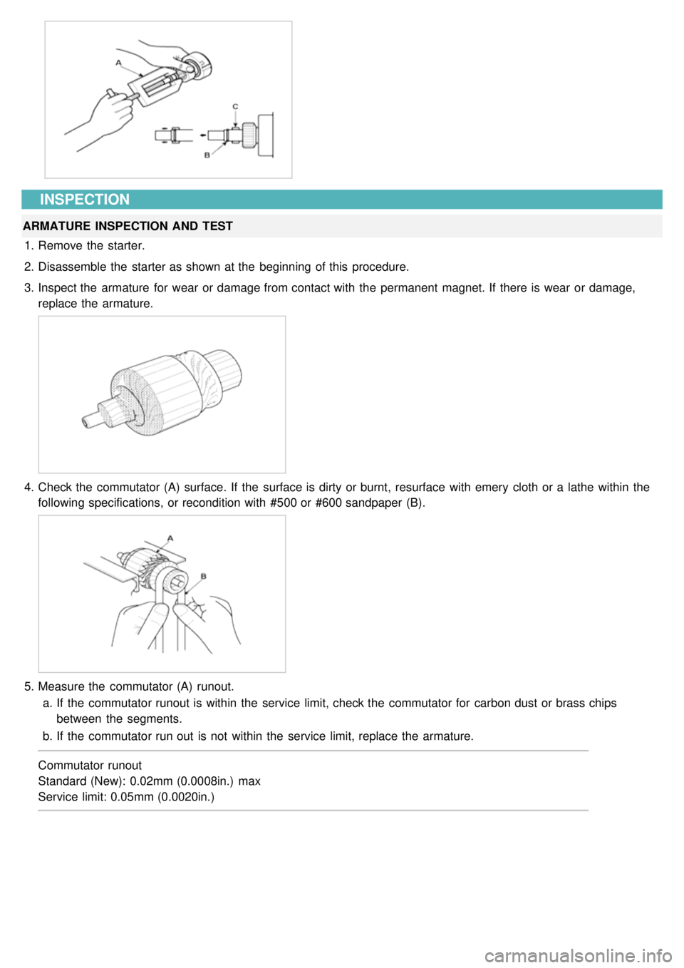
4.Check the commutator (A) surface. If the surface is dirty or burnt, resurface with emery cloth or a lathe within the
following specifications, or recondition with #500 or #600 sandpaper (B).
5.Measure the commutator (A) runout.
a. If the commutator runout is within the service limit, check the commutator for carbon dust or brass chips
between the segments.
b. If the commutator run out is not within the service limit, replace the armature.
Commutator runout
Standard (New): 0.02mm (0.0008in.) max
Service limit: 0.05mm (0.0020in.)
Page 184 of 1575
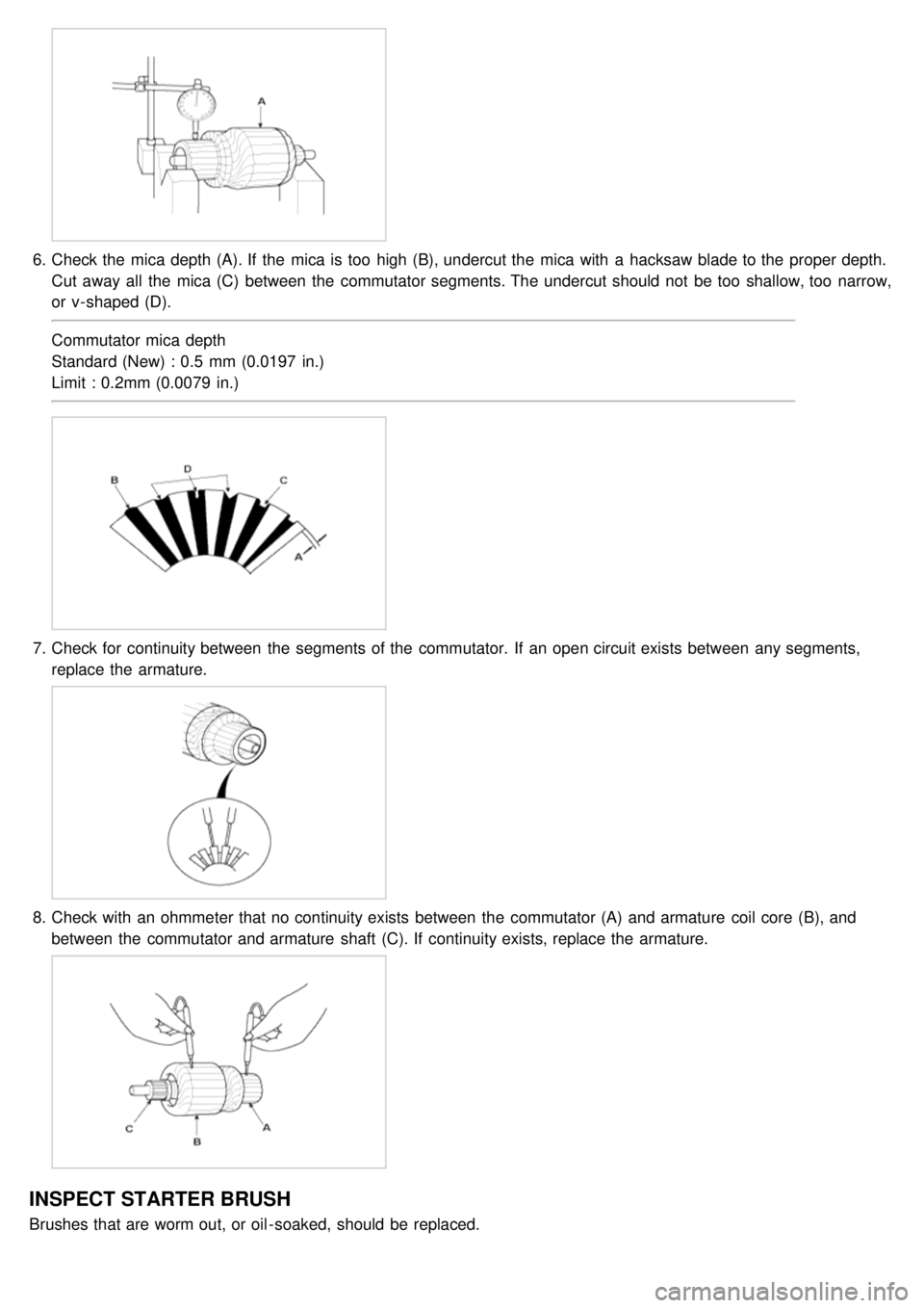
6.Check the mica depth (A). If the mica is too high (B), undercut the mica with a hacksaw blade to the proper depth.
Cut away all the mica (C) between the commutator segments. The undercut should not be too shallow, too narrow,
or v- shaped (D).
Commutator mica depth
Standard (New) : 0.5 mm (0.0197 in.)
Limit : 0.2mm (0.0079 in.)
7.Check for continuity between the segments of the commutator. If an open circuit exists between any segments,
replace the armature.
8.Check with an ohmmeter that no continuity exists between the commutator (A) and armature coil core (B), and
between the commutator and armature shaft (C). If continuity exists, replace the armature.
INSPECT STARTER BRUSH
Brushes that are worm out, or oil - soaked, should be replaced.
Page 185 of 1575
STARTER BRUSH HOLDER TEST
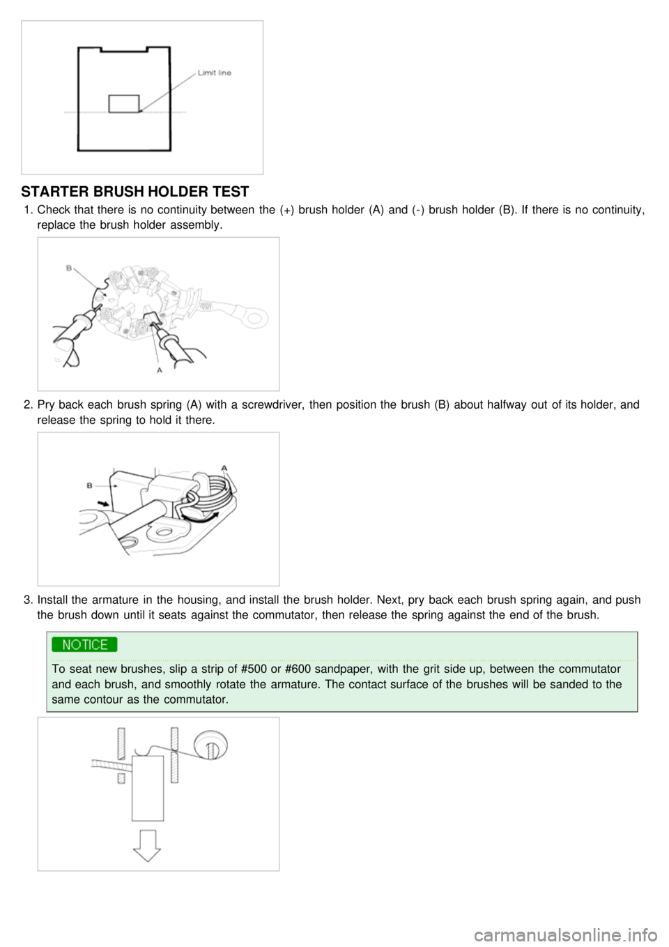
1.Check that there is no continuity between the (+) brush holder (A) and ( - ) brush holder (B). If there is no continuity,
replace the brush holder assembly.
2.Pry back each brush spring (A) with a screwdriver, then position the brush (B) about halfway out of its holder, and
release the spring to hold it there.
3.Install the armature in the housing, and install the brush holder. Next, pry back each brush spring again, and push
the brush down until it seats against the commutator, then release the spring against the end of the brush.
To seat new brushes, slip a strip of #500 or #600 sandpaper, with the grit side up, between the commutator
and each brush, and smoothly rotate the armature. The contact surface of the brushes will be sanded to the
same contour as the commutator.
Page 186 of 1575
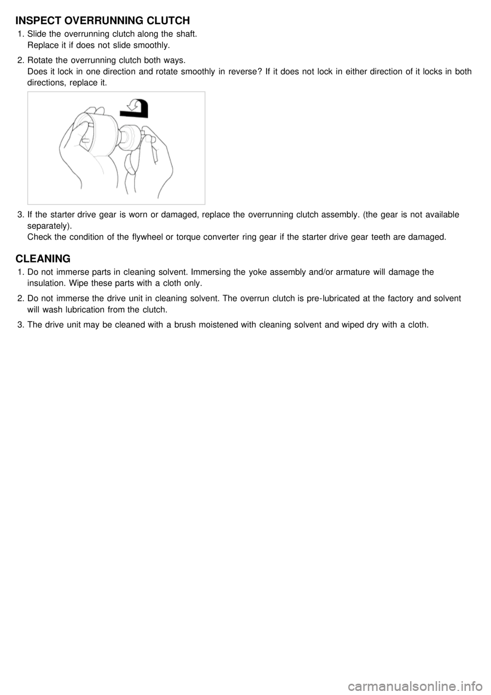
INSPECT OVERRUNNING CLUTCH
1.Slide the overrunning clutch along the shaft.
Replace it if does not slide smoothly.
2. Rotate the overrunning clutch both ways.
Does it lock in one direction and rotate smoothly in reverse? If it does not lock in either direction of it locks in both
directions, replace it.
3.If the starter drive gear is worn or damaged, replace the overrunning clutch assembly. (the gear is not available
separately).
Check the condition of the flywheel or torque converter ring gear if the starter drive gear teeth are damaged.
CLEANING
1.Do not immerse parts in cleaning solvent. Immersing the yoke assembly and/or armature will damage the
insulation. Wipe these parts with a cloth only.
2. Do not immerse the drive unit in cleaning solvent. The overrun clutch is pre- lubricated at the factory and solvent
will wash lubrication from the clutch.
3. The drive unit may be cleaned with a brush moistened with cleaning solvent and wiped dry with a cloth.
Page 187 of 1575

Starter Relay
Page 188 of 1575
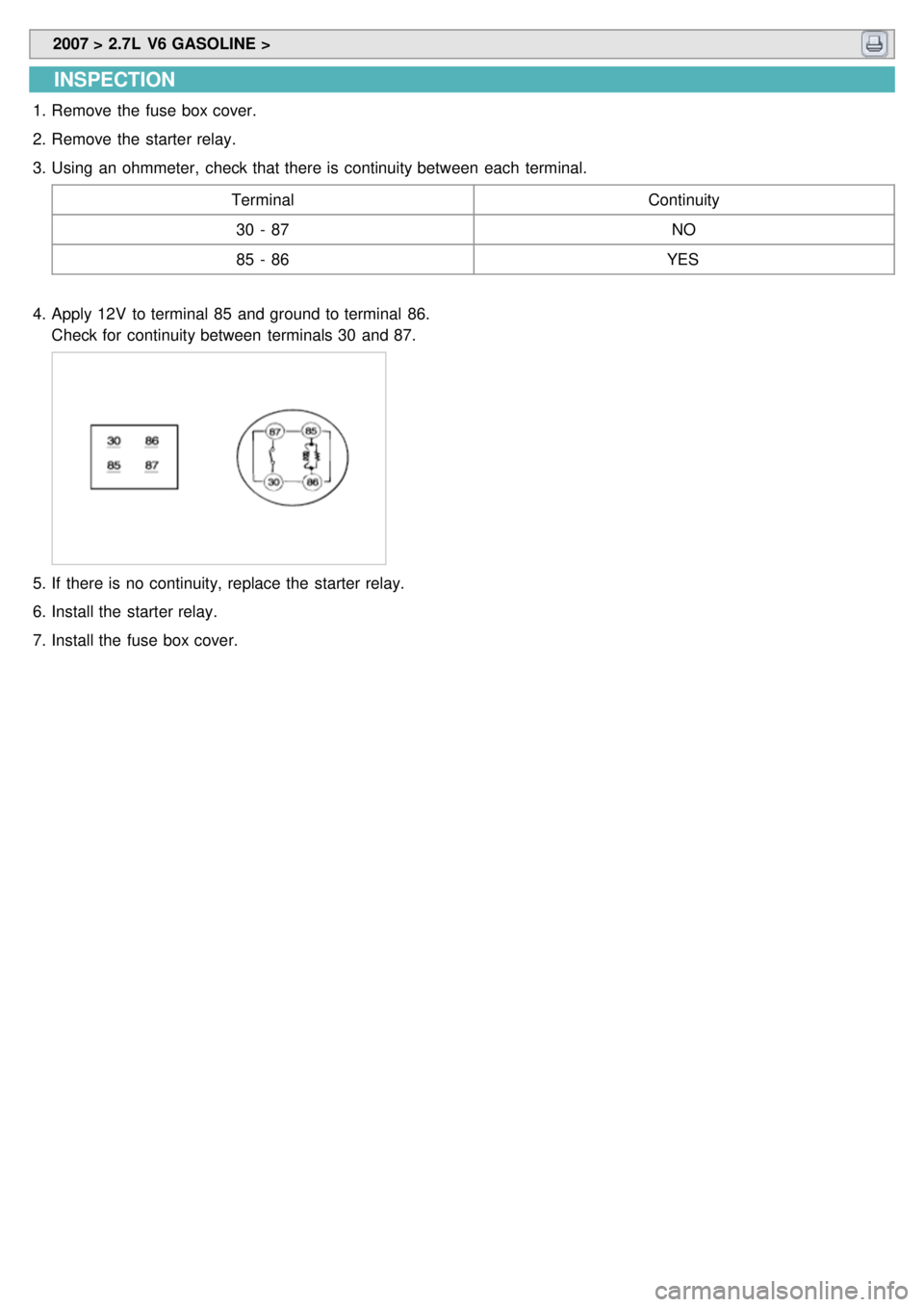
2007 > 2.7L V6 GASOLINE >
INSPECTION
1.Remove the fuse box cover.
2. Remove the starter relay.
3. Using an ohmmeter, check that there is continuity between each terminal.
Terminal Continuity
30 - 87 NO
85 - 86 YES
4. Apply 12V to terminal 85 and ground to terminal 86.
Check for continuity between terminals 30 and 87.
5.If there is no continuity, replace the starter relay.
6. Install the starter relay.
7. Install the fuse box cover.
Page 230 of 1575
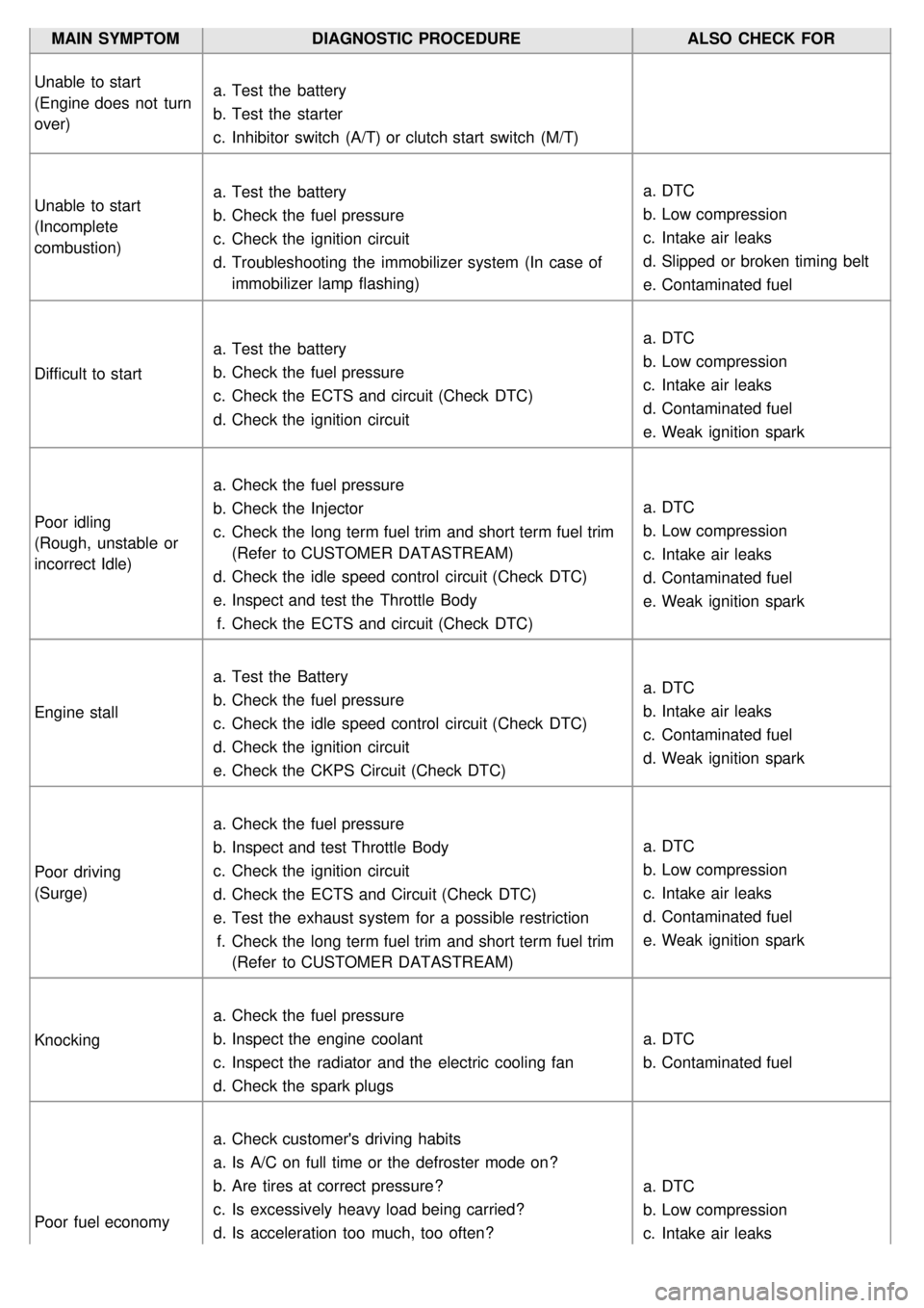
MAIN SYMPTOMDIAGNOSTIC PROCEDURE ALSO CHECK FOR
Unable to start
(Engine does not turn
over) a.
Test the battery
b. Test the starter
c. Inhibitor switch (A/T) or clutch start switch (M/T)
Unable to start
(Incomplete
combustion) a.
Test the battery
b. Check the fuel pressure
c. Check the ignition circuit
d. Troubleshooting the immobilizer system (In case of
immobilizer lamp flashing) a.
DTC
b. Low compression
c. Intake air leaks
d. Slipped or broken timing belt
e. Contaminated fuel
Difficult to start a.
Test the battery
b. Check the fuel pressure
c. Check the ECTS and circuit (Check DTC)
d. Check the ignition circuit a.
DTC
b. Low compression
c. Intake air leaks
d. Contaminated fuel
e. Weak ignition spark
Poor idling
(Rough, unstable or
incorrect Idle) a.
Check the fuel pressure
b. Check the Injector
c. Check the long term fuel trim and short term fuel trim
(Refer to CUSTOMER DATASTREAM)
d. Check the idle speed control circuit (Check DTC)
e. Inspect and test the Throttle Body
f. Check the ECTS and circuit (Check DTC) a.
DTC
b. Low compression
c. Intake air leaks
d. Contaminated fuel
e. Weak ignition spark
Engine stall a.
Test the Battery
b. Check the fuel pressure
c. Check the idle speed control circuit (Check DTC)
d. Check the ignition circuit
e. Check the CKPS Circuit (Check DTC) a.
DTC
b. Intake air leaks
c. Contaminated fuel
d. Weak ignition spark
Poor driving
(Surge) a.
Check the fuel pressure
b. Inspect and test Throttle Body
c. Check the ignition circuit
d. Check the ECTS and Circuit (Check DTC)
e. Test the exhaust system for a possible restriction
f. Check the long term fuel trim and short term fuel trim
(Refer to CUSTOMER DATASTREAM) a.
DTC
b. Low compression
c. Intake air leaks
d. Contaminated fuel
e. Weak ignition spark
Knocking a.
Check the fuel pressure
b. Inspect the engine coolant
c. Inspect the radiator and the electric cooling fan
d. Check the spark plugs a.
DTC
b. Contaminated fuel
Poor fuel economy a.
Check customer's driving habits
a. Is A/C on full time or the defroster mode on?
b. Are tires at correct pressure?
c. Is excessively heavy load being carried?
d. Is acceleration too much, too often? a.
DTC
b. Low compression
c. Intake air leaks
Page 367 of 1575
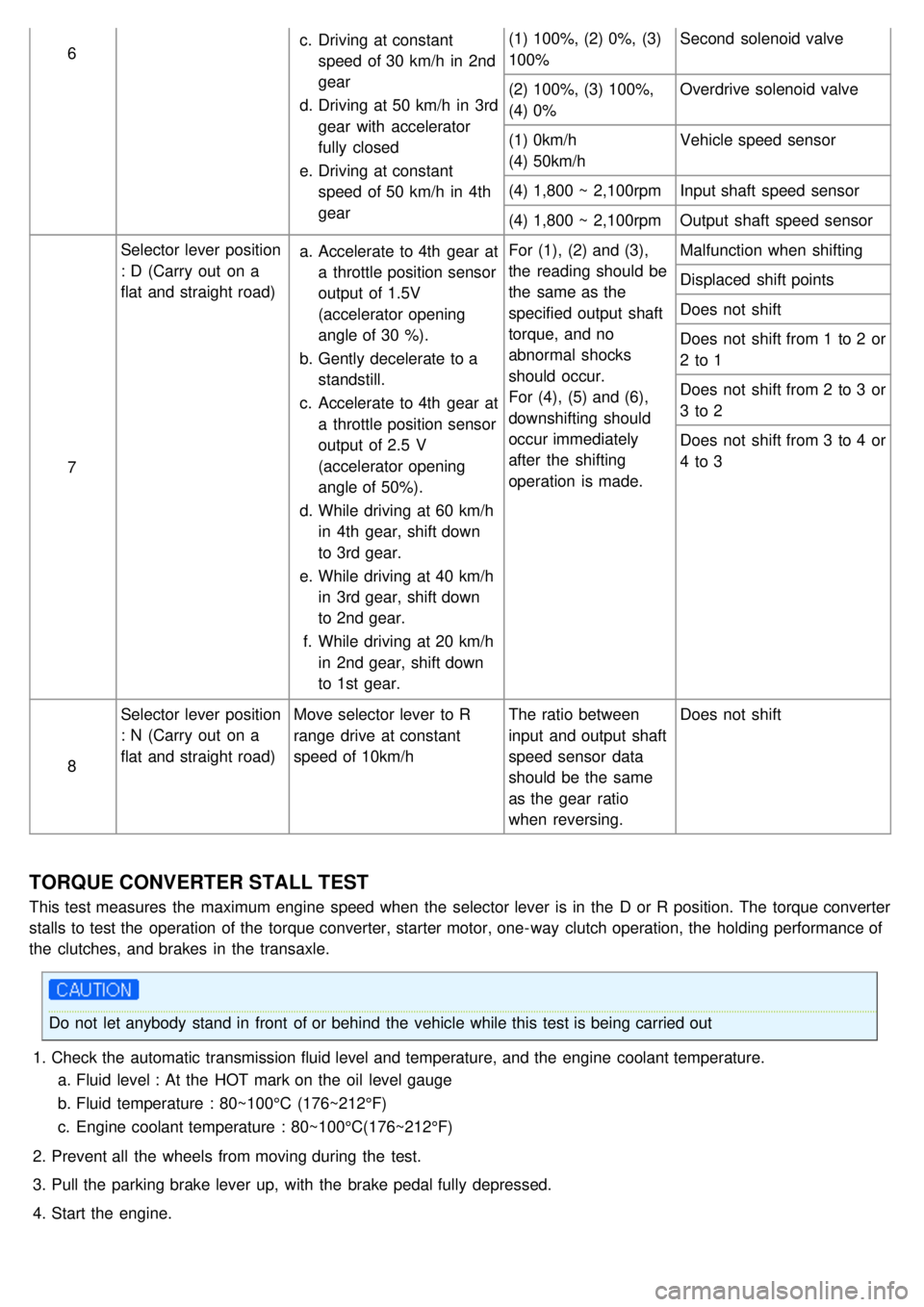
6c.
Driving at constant
speed of 30 km/h in 2nd
gear
d. Driving at 50 km/h in 3rd
gear with accelerator
fully closed
e. Driving at constant
speed of 50 km/h in 4th
gear (1) 100%, (2) 0%, (3)
100%
Second solenoid valve
(2) 100%, (3) 100%,
(4) 0% Overdrive solenoid valve
(1) 0km/h
(4) 50km/h Vehicle speed sensor
(4) 1,800 ~ 2,100rpm Input shaft speed sensor
(4) 1,800 ~ 2,100rpm Output shaft speed sensor
7 Selector lever position
: D (Carry out on a
flat and straight road)
a.
Accelerate to 4th gear at
a throttle position sensor
output of 1.5V
(accelerator opening
angle of 30 %).
b. Gently decelerate to a
standstill.
c. Accelerate to 4th gear at
a throttle position sensor
output of 2.5 V
(accelerator opening
angle of 50%).
d. While driving at 60 km/h
in 4th gear, shift down
to 3rd gear.
e. While driving at 40 km/h
in 3rd gear, shift down
to 2nd gear.
f. While driving at 20 km/h
in 2nd gear, shift down
to 1st gear. For (1), (2) and (3),
the reading should be
the same as the
specified output shaft
torque, and no
abnormal shocks
should occur.
For (4), (5) and (6),
downshifting should
occur immediately
after the shifting
operation is made.
Malfunction when shifting
Displaced shift points
Does not shift
Does not shift from 1 to 2 or
2 to 1
Does not shift from 2 to 3 or
3 to 2
Does not shift from 3 to 4 or
4 to 3
8 Selector lever position
: N (Carry out on a
flat and straight road)
Move selector lever to R
range drive at constant
speed of 10km/h The ratio between
input and output shaft
speed sensor data
should be the same
as the gear ratio
when reversing.Does not shift
TORQUE CONVERTER STALL TEST
This test measures the maximum engine speed when the selector lever is in the D or R position. The torque converter
stalls to test the operation of the torque converter, starter motor, one- way clutch operation, the holding performance of
the clutches, and brakes in the transaxle.
Do not let anybody stand in front of or behind the vehicle while this test is being carried out
1. Check the automatic transmission fluid level and temperature, and the engine coolant temperature.
a. Fluid level : At the HOT mark on the oil level gauge
b. Fluid temperature : 80~100°C (176~212°F)
c. Engine coolant temperature : 80~100°C(176~212°F)
2. Prevent all the wheels from moving during the test.
3. Pull the parking brake lever up, with the brake pedal fully depressed.
4. Start the engine.
Page 383 of 1575

13.Remove the starter motor by disconnecting the connector. (see EE group)
14. Using the SST(09200- 38001), hold the engine and transaxle assembly safely.
15.Remove the transaxle insulator mounting (B) bolts (A).
16.Remove the front wheels. (see SS group)
17. Lift up the vehicle.
18. Remove the power steering column joint bolt and the VRS connector (A). (see ST group)