battery replacement KIA CARNIVAL 2007 Workshop Manual
[x] Cancel search | Manufacturer: KIA, Model Year: 2007, Model line: CARNIVAL, Model: KIA CARNIVAL 2007Pages: 1575, PDF Size: 44.86 MB
Page 252 of 1575

2007 > 2.7L V6 GASOLINE >
PCM PROBLEM INSPECTION PROCEDURE
1.TEST PCM GROUND CIRCUIT: Measure resistance between PCM and chassis ground using the backside of PCM
harness connector as PCM side check point. If the problem is found, repair it.
Specification (Resistance): 1Ω or less
2. TEST PCM CONNECTOR: Disconnect the PCM connector and visually check the ground terminals on PCM side
and harness side for bent pins or poor contact pressure. If the problem is found, repair it.
3. If problem is not found in Step 1 and 2, the PCM could be faulty. If so, replace the PCM with a new one, and then
check the vehicle again. If the vehicle operates normally then the problem was likely with the PCM.
4. RE - TEST THE ORIGINAL PCM : Install the original PCM (may be broken) into a known- good vehicle and check
the vehicle. If the problem occurs again, replace the original PCM with a new one. If problem does not occur, this
is intermittent problem (Refer to INTERMITTENT PROBLEM PROCEDURE in BASIC INSPECTION
PROCEDURE).
REPLACEMENT
1.Turn ignition switch off.
2. Disconnect the battery ( - ) cable from the battery.
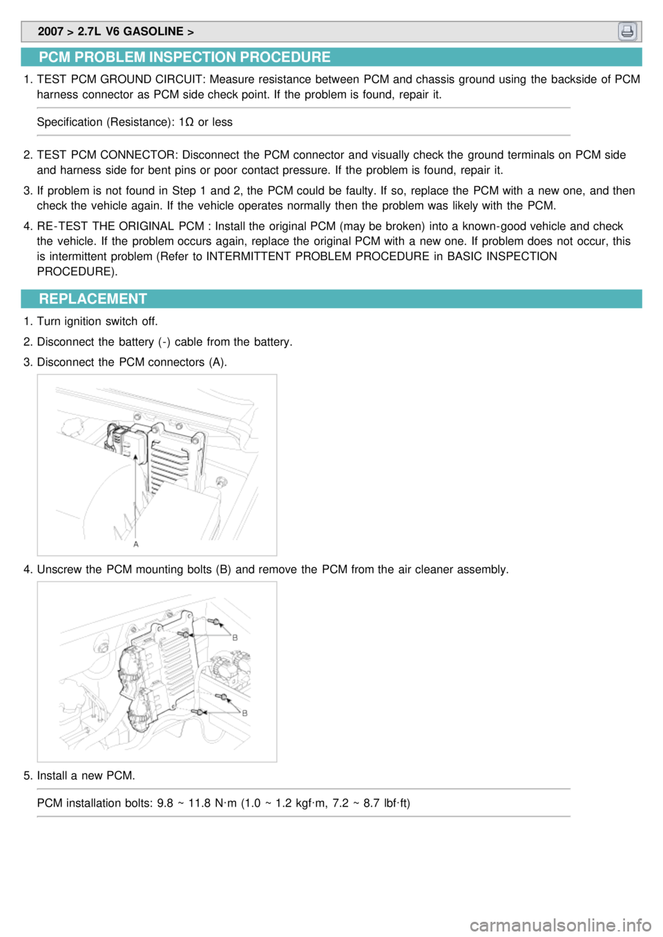
3. Disconnect the PCM connectors (A).
4.Unscrew the PCM mounting bolts (B) and remove the PCM from the air cleaner assembly.
5.Install a new PCM.
PCM installation bolts: 9.8 ~ 11.8 N·m (1.0 ~ 1.2 kgf·m, 7.2 ~ 8.7 lbf·ft)
Page 405 of 1575

2007 > 2.7L V6 GASOLINE >
REPLACEMENT
1.Remove the battery and air cleaner (see "Transaxle range switch replacement").
2. Remove the transaxle range switch connector.
3. Remove the control cable to transaxle range switch mounting nut.
4. Remove the input shaft speed sensor(A).
(1) Disconnect the input shaft speed sensor connector.
(2) Remove the bolt(B).
(3)Inspect the input shaft speed sensor bore.
5. Apply a light coat of automatic transaxle fluid to the O - ring seal before installation.
6. Install the input shaft speed sensor.
7. Install the control cable mounting bracket.
8. Connect the input shaft speed sensor connector.
9. Install the holder of the control cable.
10. Adjust the control cable to transaxle range switch and tighten the transaxle manual lever to the control cable
mounting nut. (see "Automatic transaxle shift control installation")
11. Installation is the reverse of removal.
Page 409 of 1575

2007 > 2.7L V6 GASOLINE >
REPLACEMENT
1.Remove the battery and air cleaner. (see "Transaxle range switch replacement")
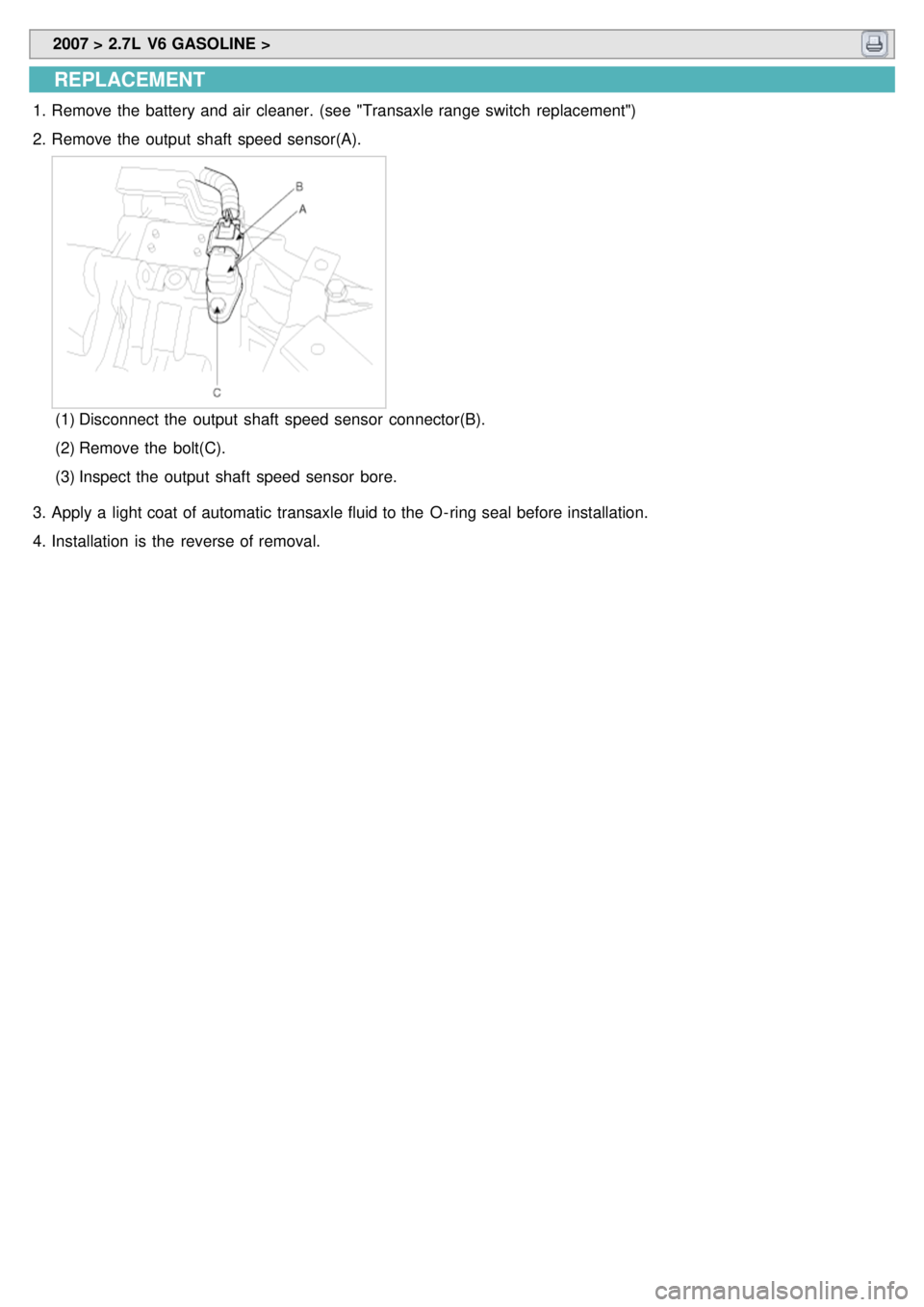
2. Remove the output shaft speed sensor(A).
(1) Disconnect the output shaft speed sensor connector(B).
(2) Remove the bolt(C).
(3) Inspect the output shaft speed sensor bore.
3. Apply a light coat of automatic transaxle fluid to the O - ring seal before installation.
4. Installation is the reverse of removal.
Page 415 of 1575

2007 > 2.7L V6 GASOLINE >
REPLACEMENT
1.Pull up the parking brake.
2. Position the shift lever in 'N' range.
3. Remove the air cleaner assembly.
4. Remove the battery.
5. Remove the battery tray.
6. Remove the inhibiter switch connector.
7. Remove the shift cable mounting nut(A).
8.Remove the inhibiter switch loosening the mounting bolts.
9. Refering to 'INSPECTION', check for continuity. If there is an error, replace the inhibiter switch.
10. After tightening the shift cable mounting nut, connect the inhibiter switch.
11. Install the battery, battery tray and the air cleaner assembly.
INSPECTION
1.Check for the starter motor when the ignition switch is at 'START' position and the shift lever at 'P' or 'N' range.
2. Check for the rear lamp when the ignition switch if it does not work properly.
3. Check for the inhibiter switch if it does not work properly.
4. If the inhibiter switch is not fixed in a proper position, reassemble it in the right position.
5. Re- check 1 and 2 procedures.
6. Using a scan tool, confirm the DTCs.
7. Disconnect the battery ( - ) terminal and the inhibiter switch.
8. Check for continuity between terminals at the switch connector.
Page 668 of 1575

2007 > 2.7L V6 GASOLINE >
INSPECTION
1.Check the condenser fins for clogging and damage. If clogged, clean them with water, and blow them with
compressed air. If bent, gently bend them using a screwdriver or pliers.
2. Check the condenser connections for leakage, and repair or replace it, if required.
REPLACEMENT
CONDENSER ASSEMBLY
1. Recover the refrigerant with a recovery/ recycling/ charging station (Refer to HA - 8).
2. Disconnect the negative ( - ) battery terminal.
3. Remove the radiator. (Refer to EM group)
4. Remove 2 bolts, and then remove the condenser (A) by lifting it up. Be careful not to damage the radiator and
condenser fins when removing the condenser.
5.Install in the reverse order of removal, and note these items :
a. If you're installing a new condenser, add refrigerant oil ND- OIL8.
b. Replace the O - rings with new ones at each fitting, and apply a thin coat of refrigerant oil before installing them.
Be sure to use the right O - rings for R- 134a to avoid leakage.
c. Be careful not to damage the radiator and condenser fins when installing the condenser.
d. Be sure to install the lower mount cushions of condenser securely into the holes.
e. Charge the system, and test its performance. (Refer to HA - 9)
DESICCANT
1.Remove the condenser, and then remove the bottom cap (B) with L wrench (A) from the condenser.
TORQUE: 20~25N.m (2.0~2.5kgf•m, 14.5~18.2lb - ft)
Page 676 of 1575

2007 > 2.7L V6 GASOLINE >
INSPECTION
1.Measure the pressure of high pressure line by measuring voltage output between NO.1 and NO.2 terminals.
2.Inspect the voltage value whether it is sufficient to be regular value or not.
Vout = Vdd(0.025 * P + 0.1) [kgf/cm²G]
Vout = Vdd(0.001758 * P + 0.074162) [PSIA]
3. If the measured voltage value is not specification, replace the A/C pressure transducer.
REPLACEMENT
1.Disconnect the negative ( - ) battery terminal.
2. Recover the refrigerant with a recovery/charging station.
3. Disconnect A/C pressure transducer connector (3P) (A).
Page 680 of 1575

2007 > 2.7L V6 GASOLINE >
INSPECTION
1.Ignition "OFF"
2. Disconnect evaporator temperature sensor.
3. Using the multi- tester, Measure resistance between terminal "1" and "2" of evaporator temperature sensor.
Specification
Evaporator core temperature [°C(°F)] Resistance [kΩ]
- 10(14) 13.6
0(32) 8
10(50) 4.9
15(59) 3.9
30(86) 2
40(104) 1.3
50(122) 0.9
4. If the measured resistance is not specification, substitute with a known- good evaporator temperature sensor and
check for proper operation.
5. If the problem is corrected, replace the evaporator temperature sensor.
REPLACEMENT
1.Disconnect the negative ( - ) battery terminal.
2. Remove the center lower side cover(B).
Page 685 of 1575

2007 > 2.7L V6 GASOLINE >
INSPECTION
1.Ignition "ON"
2. Blow air with changing temperature to the in car sensor air inlet. Measure sensor resistance between 2 and 4
terminals.
Specification
Temperature [°C(°F)] Resistance between terminals 2and 4 (kΩ)
0 (32) 97.83 ± 2.61%
15 (59) 47.12 ± 1.45%
25 (77) 30.00 ± 1.20%
35 (95) 19.60 ± 1.44%
50 (122) 10.82 ± 2.26%
In car sensor is negative type thermistor that resistance will rise with lower temperature, and reduce with
higher temperature.
REPLACEMENT
1.Disconnect the negative ( - ) battery terminal.
2. Remove the A/C control pannel. (Refer to BD group).
3. Disconnect the connector of in - car sensor (A).Loosen the mounting 2 screws and then remove the in - car sensor
(B).
4.Installation is the reverse order of removal.
Page 689 of 1575

2007 > 2.7L V6 GASOLINE >
INSPECTION
1.Ignition "ON"
2. Using the scan tool.
3. Emit intensive light toward photo sensor using a lamp, and check the output voltage change.
4. The voltage will rise with higher intensive light and reduce with lower intensive light.
REPLACEMENT
1.Disconnect the negative ( - ) battery terminal.
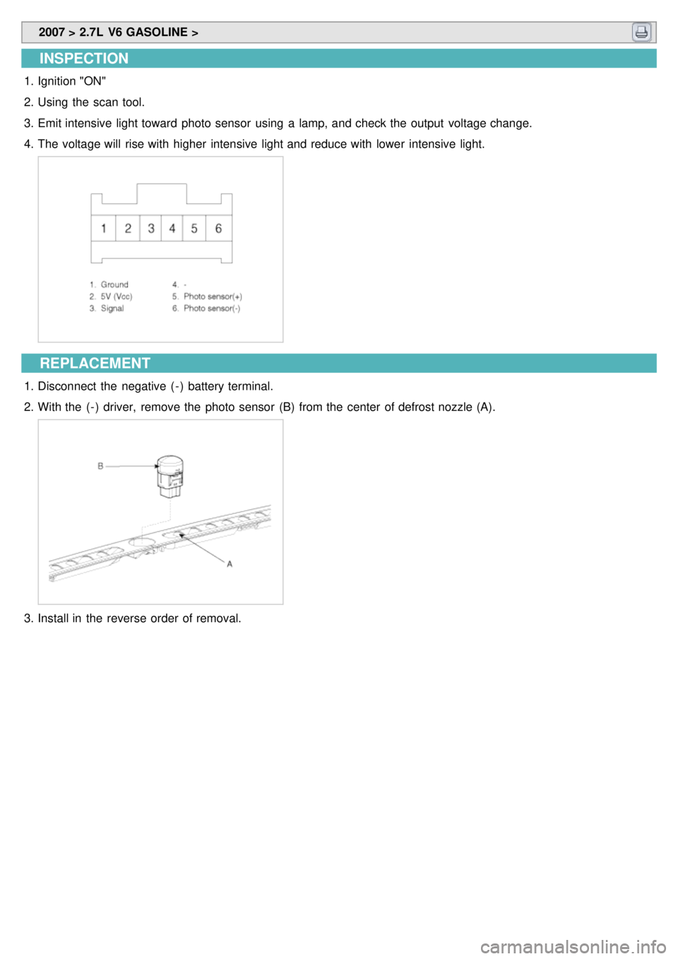
2. With the ( - ) driver, remove the photo sensor (B) from the center of defrost nozzle (A).
3.Install in the reverse order of removal.
Page 693 of 1575

2007 > 2.7L V6 GASOLINE >
INSPECTION
1.Ignition "ON"
2. Using the multi- tester, Measure resistance between terminal "1" and "2" of water temperature sensor.
Specification
Coolant temperature [°C(°F)] Resistance (kΩ)Voltage (V)
- 10(14) 55.85 ± 3% 4.24 ± 3%
0(32) 32.91 ± 3% 3.83 ± 3%
10(50) 19.99 ± 3% 3.33 ± 3%
20(68) 12.51 ± 3% 2.78 ± 3%
30(86) 8.047 ± 3% 2.23 ± 3%
40(104) 5.311 ± 3% 1.73 ± 3%
50(122) 3.588 ± 3% 1.32 ± 3%
60(140) 2.476 ± 3% 0.99 ± 3%
70(158) 1.742 ±3% 0.74 ± 3%
80(176) 1.246 ± 3% 0.55 ± 3%
3. If the measured resistance is not specification, substitute with a known- good water temperature sensor and check
for proper operation.
4. If the problem is corrected, replace the water temperature sensor.
Negative type thermistor that resistance will rise with lower temperature, and reduce with higher temperature.
REPLACEMENT
1.Disconnect the negative ( - ) battery terminal.
2. Remove the grove box. (Refer to BD group)
3. Disconnect the connector (B) of water temperature sensor and then remove the water temperature sensor(A) by
pulling out.