relay KIA CARNIVAL 2007 Owner's Manual
[x] Cancel search | Manufacturer: KIA, Model Year: 2007, Model line: CARNIVAL, Model: KIA CARNIVAL 2007Pages: 1575, PDF Size: 44.86 MB
Page 366 of 1575

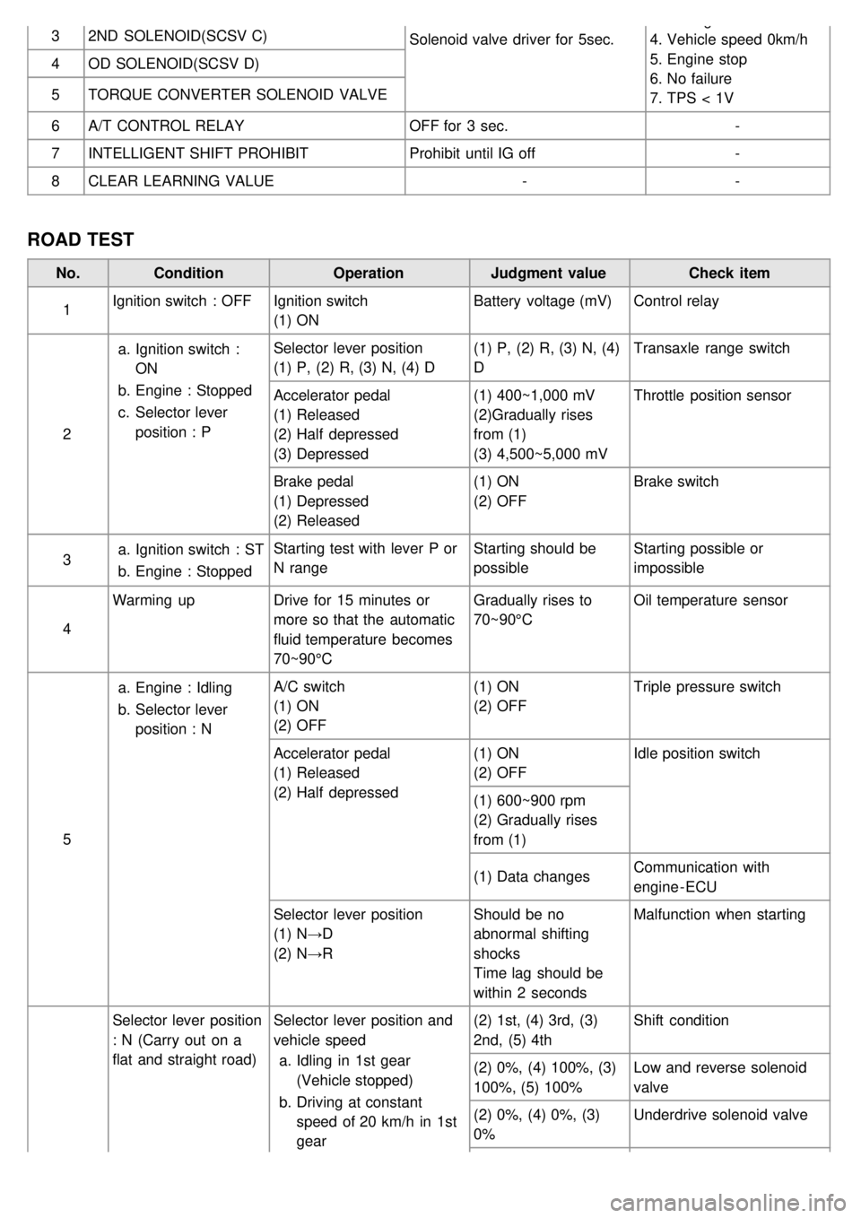
32ND SOLENOID(SCSV C)
Solenoid valve driver for 5sec.3. P range
4. Vehicle speed 0km/h
5. Engine stop
6. No failure
7. TPS < 1V
4
OD SOLENOID(SCSV D)
5 TORQUE CONVERTER SOLENOID VALVE
6 A/T CONTROL RELAY OFF for 3 sec. -
7 INTELLIGENT SHIFT PROHIBIT Prohibit until IG off -
8 CLEAR LEARNING VALUE --
ROAD TEST
No.Condition OperationJudgment value Check item
1 Ignition switch : OFF
Ignition switch
(1) ON Battery voltage (mV)
Control relay
2 a.
Ignition switch :
ON
b. Engine : Stopped
c. Selector lever
position : P Selector lever position
(1) P, (2) R, (3) N, (4) D
(1) P, (2) R, (3) N, (4)
DTransaxle range switch
Accelerator pedal
(1) Released
(2) Half depressed
(3) Depressed (1) 400~1,000 mV
(2)Gradually rises
from (1)
(3) 4,500~5,000 mVThrottle position sensor
Brake pedal
(1) Depressed
(2) Released (1) ON
(2) OFF
Brake switch
3 a.
Ignition switch : ST
b. Engine : Stopped Starting test with lever P or
N range
Starting should be
possibleStarting possible or
impossible
4 Warming up
Drive for 15 minutes or
more so that the automatic
fluid temperature becomes
70~90°C Gradually rises to
70~90°C
Oil temperature sensor
5 a.
Engine : Idling
b. Selector lever
position : N A/C switch
(1) ON
(2) OFF
(1) ON
(2) OFF
Triple pressure switch
Accelerator pedal
(1) Released
(2) Half depressed (1) ON
(2) OFF
Idle position switch
(1) 600~900 rpm
(2) Gradually rises
from (1)
(1) Data changes Communication with
engine - ECU
Selector lever position
(1) N→D
(2) N→R Should be no
abnormal shifting
shocks
Time lag should be
within 2 secondsMalfunction when starting
Selector lever position
: N (Carry out on a
flat and straight road) Selector lever position and
vehicle speed
a. Idling in 1st gear
(Vehicle stopped)
b. Driving at constant
speed of 20 km/h in 1st
gear (2) 1st, (4) 3rd, (3)
2nd, (5) 4th
Shift condition
(2) 0%, (4) 100%, (3)
100%, (5) 100% Low and reverse solenoid
valve
(2) 0%, (4) 0%, (3)
0% Underdrive solenoid valve
Page 646 of 1575

2007 > 2.7L V6 GASOLINE >
TROUBLESHOOTING
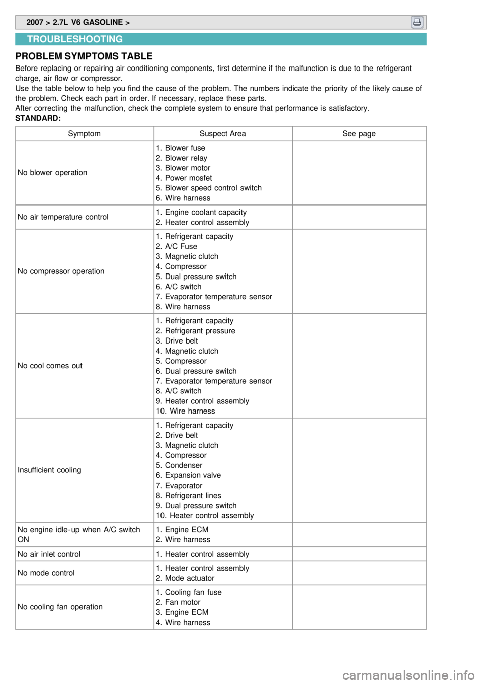
PROBLEM SYMPTOMS TABLE
Before replacing or repairing air conditioning components, first determine if the malfunction is due to the refrigerant
charge, air flow or compressor.
Use the table below to help you find the cause of the problem. The numbers indicate the priority of the likely cause of
the problem. Check each part in order. If necessary, replace these parts.
After correcting the malfunction, check the complete system to ensure that performance is satisfactory.
STANDARD:
Symptom Suspect Area See page
No blower operation 1. Blower fuse
2. Blower relay
3. Blower motor
4. Power mosfet
5. Blower speed control switch
6. Wire harness
No air temperature control 1. Engine coolant capacity
2. Heater control assembly
No compressor operation 1. Refrigerant capacity
2. A/C Fuse
3. Magnetic clutch
4. Compressor
5. Dual pressure switch
6. A/C switch
7. Evaporator temperature sensor
8. Wire harness
No cool comes out 1. Refrigerant capacity
2. Refrigerant pressure
3. Drive belt
4. Magnetic clutch
5. Compressor
6. Dual pressure switch
7. Evaporator temperature sensor
8. A/C switch
9. Heater control assembly
10. Wire harness
Insufficient cooling 1. Refrigerant capacity
2. Drive belt
3. Magnetic clutch
4. Compressor
5. Condenser
6. Expansion valve
7. Evaporator
8. Refrigerant lines
9. Dual pressure switch
10. Heater control assembly
No engine idle - up when A/C switch
ON 1. Engine ECM
2. Wire harness
No air inlet control 1. Heater control assembly
No mode control 1. Heater control assembly
2. Mode actuator
No cooling fan operation 1. Cooling fan fuse
2. Fan motor
3. Engine ECM
4. Wire harness
Page 679 of 1575

2007 > 2.7L V6 GASOLINE >
DESCRIPTION
The evaporator temperature sensor will detect the evaporator core temperature and interrupt compressor relay power
in order to prevent evaporator freezing by excessive cooling.
Page 737 of 1575

2007 > 2.7L V6 GASOLINE >
INSPECTION
Inspect the PTC operation by confirmation logic as below.
1. Entering method
(1) Set the floor mode, maximum heating
(2) Turn off the blower switch
(3) Press the intake button more than 5 times.
(4) Indicator of entire button is flashed with an interval of 0.5 seconds continuously (Manual).
Graphics of the entire LCD display switch on and off with an interval of 0.5 seconds continuously (Automatic)
(5) Confirm the PTC operation by operating the blower switch
Manual : 1~4 step, Automatic: 1~8step.
(6) Each PTC relay is operated with an interval of 3 seconds.
(7) Execute the PTC operation by confirmation logic for 30 seconds.
2. Cancellation method
(1) Select the A/C button or intake button.
(2) IG "OFF".
(3) Cancel the logic after 30 seconds automatically.
3. If the PTC operation is not operated, substitute with a known- good PTC and check for proper operation.
If the problem is corrected, replace the PTC.
Page 766 of 1575

Blower Relay
Page 768 of 1575

2007 > 2.7L V6 GASOLINE >
INSPECTION
1.There should be continuity between the NO.1 in the A and NO.10 in the B terminals when power and ground are
connected to the NO.7 and NO.13 in the A terminals. (Passenger compartment relay box)
2. There should be to no continuity btween the NO.1 in the A and NO.10 in the B terminals when power is
disconnected.
REAR BLOWER
1.There should be continuity between the NO.4in the A and NO.12n the B terminals when power and ground are
connected to the NO.2and NO.14in the A terminals. (Passenger compartment relay box)
2. There should be to no continuity btween the NO.4in the A and NO.12in the B terminals when power is
disconnected.
REPLACEMENT
1.Disconnect the negative ( - ) battery terminal.
2. Remove the crash pad center lower side cover. (Refer to BD group)
3. Loosen the relat box mounting nut, and then remove the relay box(A).
4.Install in the reverse order of removal.
Page 783 of 1575

Connector AConnector B
6 REAR TEMP ACTUATOR
(F/B) 12
SENSOR POWER (+5V)
7 REAR TEMP SWITCH 13-
8 REAR MODE ACTUATOR
(VENT) 14
HAZARD SEIECT
9 REAR MODE ACTUATOR
(FLOOR) 15
-
10 REAR MODE ACTUATOR
(F/B) 16
-
11 BLOWER MOTOR (+)
Connector C1
DRIVE'S TEMP ACTUATOR
(COOL)
12 GROUND 2DRIVE'S TEMP ACTUATOR
(WARM)
13 RHEOSTAT (ILL- ) 3DRIVE'S TEMP ACTUATOR (F/B)
14 A/C SELECT SIGNAL 4DRIVE'S MODE ACTUATOR
(COOL)
15 A/C OUTPUT 5DRIVE'S MODE ACTUATOR
(WARM)
16 REAR DEFOGGER 6DRIVE'S MODE ACTUATOR (F/B)
17 REAR DEFOGGER
SWITCH 7
INTAKE ACTUATOR (FRESH)
18 - 8INTAKE ACTUATOR
(RECIRCULATION)
19 REAR BLOWER SWITCH 9INTAKE ACTUATOR (F/B)
20 REAR MODE SWITCH
(VENT) 10
PASSENGER'S TEMP ACTUATOR
(COOL)
21 REAR MODE SWITCH (B/L) 11EVAPORATOR SENSOR (+)
22 REAR MODE SWITCH
(FLOOR) 12
SENSOR POWER (+5V)
23 REAR MODE GND (VENT) 13PASSENGER'S TEMP ACTUATOR
(WARM)
24 REAR MODE GND (B/L) 14PASSENGER'S TEMP ACTUATOR
(F/B)
25 REAR MODE GND
(FLOOR) 15
-
26 - 16DATA PORT
Connector B 1
- 17RESET PIN
2 A/C OUTPUT 18-
3 PTC RELAY2 19POWER MOSFET (GATE) -
FRONT
4 PTC RELAY3 20POWER MOSFET (DRAIN) -
FRONT
5 BLOWER SELECT SIGNAL 21SENSOR GND
6 PTC ON SIGNAL 22-
Page 787 of 1575

Connector AConnector B
6 REAR TEMP ACTUATOR
(F/B) 12
SENSOR POWER (+5V)
7 REAR TEMP SWITCH 13-
8 REAR MODE ACTUATOR
(VENT) 14
HAZARD SEIECT
9 REAR MODE ACTUATOR
(FLOOR) 15
-
10 REAR MODE ACTUATOR
(F/B) 16
-
11 BLOWER MOTOR (+)
Connector C1
DRIVE'S TEMP ACTUATOR
(COOL)
12 GROUND 2DRIVE'S TEMP ACTUATOR
(WARM)
13 RHEOSTAT (ILL- ) 3DRIVE'S TEMP ACTUATOR (F/B)
14 A/C SELECT SIGNAL 4DRIVE'S MODE ACTUATOR
(COOL)
15 A/C OUTPUT 5DRIVE'S MODE ACTUATOR
(WARM)
16 REAR DEFOGGER 6DRIVE'S MODE ACTUATOR (F/B)
17 REAR DEFOGGER
SWITCH 7
INTAKE ACTUATOR (FRESH)
18 - 8INTAKE ACTUATOR
(RECIRCULATION)
19 REAR BLOWER SWITCH 9INTAKE ACTUATOR (F/B)
20 REAR MODE SWITCH
(VENT) 10
PASSENGER'S TEMP ACTUATOR
(COOL)
21 REAR MODE SWITCH (B/L) 11EVAPORATOR SENSOR (+)
22 REAR MODE SWITCH
(FLOOR) 12
SENSOR POWER (+5V)
23 REAR MODE GND (VENT) 13PASSENGER'S TEMP ACTUATOR
(WARM)
24 REAR MODE GND (B/L) 14PASSENGER'S TEMP ACTUATOR
(F/B)
25 REAR MODE GND
(FLOOR) 15
-
26 - 16DATA PORT
Connector B 1
- 17RESET PIN
2 A/C OUTPUT 18-
3 PTC RELAY2 19POWER MOSFET (GATE) -
FRONT
4 PTC RELAY3 20POWER MOSFET (DRAIN) -
FRONT
5 BLOWER SELECT SIGNAL 21SENSOR GND
6 PTC ON SIGNAL 22-
Page 866 of 1575

TIGHTENING TORQUE
ItemsNmkgf.m lb - ft
Master cylinder to booster mounting nut 8 ~ 120.8 ~ 1.2 5.8 ~ 8.7
Brake booster mounting nut 13 ~ 161.3 ~ 1.6 9.4 ~ 11.6
Bleeder screw 7 ~ 130.7 ~ 1.3 5.06 ~ 9.4
Brake tube nut, brake hose 13 ~ 171.3 ~ 1.7 9.4 ~ 12.3
Caliper guide rod bolt (Front) 22 ~ 322.2 ~ 3.215.9 ~ 23.1
Caliper guide rod bolt (Rear) 22 ~ 322.2 ~ 3.215.9 ~ 23.1
Caliper assembly to knuckle (Front) 85 ~ 1008.5 ~ 1061.5 ~ 72.3
Caliper assembly to knuckle (Rear) 50 ~ 605.0 ~ 6.036.2 ~ 43.4
Brake hose to front caliper 25 ~ 302.5 ~ 3.018.1 ~ 21.7
Brake pedal assembly bracket mounting nut 10 ~ 151.0 ~ 1.5 7.2 ~ 10.8
Brake pedal mounting nut 13 ~ 161.3 ~ 1.6 9.4 ~ 11.6
Stop lamp switch mounting nut 8 ~ 100.8 ~ 1.0 5.8 ~ 7.23
Active wheel speed sensor mounting bolt on
the brake plate 7 ~ 10
0.7 ~ 1.0 5.1 ~ 7.2
HECU mounting bracket bolt 17 ~ 261.7 ~ 2.612.3 ~ 18.8
HECU mounting nut 6 ~ 100.6 ~ 1.0 4.3 ~ 7.2
Yaw rate & lateral acceleration sensor bolt 5 ~ 80.5 ~ 0.8 3.62 ~ 5.8
SPECIFICATION (ABS)
Part ItemStandard valueRemark
HECU(Hydraulic and
Electronic Control
Unit) System
4 channel 4 sensor
(Solenoid)
·ABS system:ABS &
EBD control
Type
Motor, valve relay
intergrated type
Operating voltage 8 V ~ 16 V(DC)
Operating temperature - 40 ~ 120 °C
( - 40 ~ 248 °F)
Warning lamp Operating voltage
12 V·ABS W/L:ABS failure
·Brake W/L:Parking,
brake oil, EBD failure
Current consumption 80 mA
Acitve wheel speed
sensor Supply voltage
DC 4.5 ~ 2.0 V
Operating temperature - 40 ~ 150 °C
Output current low 5.9 ~ 8.4 mATyp.7 mA
Output current High 11.8 ~ 16.8 mATyp.14 mA
Frequency range 1 ~ 2500 HZ
Air gap Front
0.15 ~ 1.5 mm Typ.0.7 mm
Rear 0.2 ~ 1.2 mm Typ.0.7 mm
Tone wheel 48 teeth
Output duty 30~70 %
SPECIFICATION(ESP)
Page 867 of 1575

PartItemStandard ValueRemark
HECU(Hydraulic and
Electronic Control
Unit) System
4 channel 4
sensor(Solenoid)
·Total control(ABS,
EBD, TCS, ESP)
Type
Motor, valve relay
intergrated type
Operating voltage 8 V ~ 16 V(DC)
Operating temperature - 40 ~ 120 °C(- 40 ~
248 °F)
Warning lamp Operating voltage
12 V
·ESP Operating Lamp
·ESP Warning Lamp
Current consumption 80 mA
Active wheel speed
sensor Supply voltage
DC 4.5 ~ 20V
Operating temperature - 40 ~ 150 °C
Output current low 5.9 ~ 8.4 mA
Output current high 11.8 ~ 16.8 mA
Tone wheel 48 teeth
Frequency range 1 ~ 2500 HZ
Airgap Front
0.15 ~ 1.5 mm Typ. 0.7 mm
Rear 0.2 ~ 1.2 mm Typ. 0.7 mm
Steering Wheel Angle
Sensor Operating Voltage
8V ~ 16 V
Current Consumption Max 150 mA
Operating Angular velocity Max ± 780 °/sec
Yaw - rate & Lateral G
sensor Operating Voltage
8 V ~ 16 V
Current Consumption Max. 120 mA
Output Voltage high 4.35 V~ 4.65 VTyp. 4.5 V
Output Voltage low 0.35 ~ 0.65 VTyp. 0.5 V
Yaw Sensor Operating Range ±100 ° /s
G Sensor Operating Range ±1.8 G
Reference voltage output 2.464 ~ 2.536 VTyp. 2.5 V
LUBRICANT
Item Recommended lubricantQuantity
Brake fluid DOT 3 or DOT 4As required
Brake pedal bushing and brake pedal bolt Chassis greaseAs required
Parking brake shoe and backing plate contact surfaces Bearing greaseAs required
Caliper guide rod and boot RX - 2 grease0.8 ~ 1.3 g
Rear caliper guide rod and boot Rubber grease0.8 ~ 1.3g