KIA CARNIVAL 2007 Service Manual
CARNIVAL 2007
KIA
KIA
https://www.carmanualsonline.info/img/2/57045/w960_57045-0.png
KIA CARNIVAL 2007 Service Manual
Page 1248 of 1575

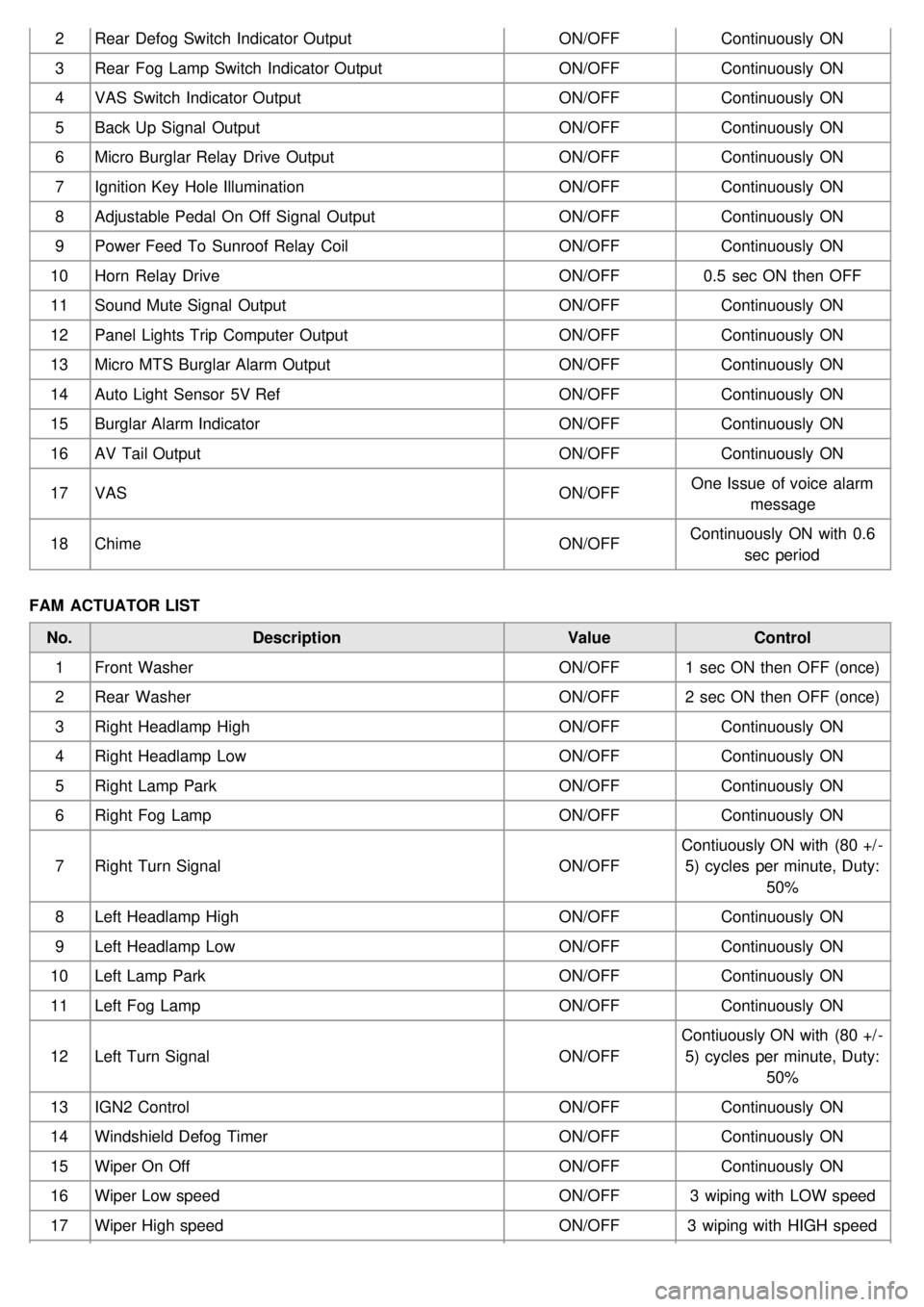
2Rear Defog Switch Indicator Output ON/OFFContinuously ON
3 Rear Fog Lamp Switch Indicator Output ON/OFFContinuously ON
4 VAS Switch Indicator Output ON/OFFContinuously ON
5 Back Up Signal Output ON/OFFContinuously ON
6 Micro Burglar Relay Drive Output ON/OFFContinuously ON
7 Ignition Key Hole Illumination ON/OFFContinuously ON
8 Adjustable Pedal On Off Signal Output ON/OFFContinuously ON
9 Power Feed To Sunroof Relay Coil ON/OFFContinuously ON
10 Horn Relay Drive ON/OFF0.5 sec ON then OFF
11 Sound Mute Signal Output ON/OFFContinuously ON
12 Panel Lights Trip Computer Output ON/OFFContinuously ON
13 Micro MTS Burglar Alarm Output ON/OFFContinuously ON
14 Auto Light Sensor 5V Ref ON/OFFContinuously ON
15 Burglar Alarm Indicator ON/OFFContinuously ON
16 AV Tail Output ON/OFFContinuously ON
17 VAS ON/OFFOne Issue of voice alarm
message
18 Chime ON/OFFContinuously ON with 0.6
sec period
FAM ACTUATOR LIST No. Description ValueControl
1 Front Washer ON/OFF1 sec ON then OFF (once)
2 Rear Washer ON/OFF2 sec ON then OFF (once)
3 Right Headlamp High ON/OFFContinuously ON
4 Right Headlamp Low ON/OFFContinuously ON
5 Right Lamp Park ON/OFFContinuously ON
6 Right Fog Lamp ON/OFFContinuously ON
7 Right Turn Signal ON/OFFContiuously ON with (80 +/ -
5) cycles per minute, Duty: 50%
8 Left Headlamp High ON/OFFContinuously ON
9 Left Headlamp Low ON/OFFContinuously ON
10 Left Lamp Park ON/OFFContinuously ON
11 Left Fog Lamp ON/OFFContinuously ON
12 Left Turn Signal ON/OFFContiuously ON with (80 +/ -
5) cycles per minute, Duty: 50%
13 IGN2 Control ON/OFFContinuously ON
14 Windshield Defog Timer ON/OFFContinuously ON
15 Wiper On Off ON/OFFContinuously ON
16 Wiper Low speed ON/OFF3 wiping with LOW speed
17 Wiper High speed ON/OFF3 wiping with HIGH speed
Page 1285 of 1575
Page 1287 of 1575
Relay Box
(Engine Compartment)
Page 1290 of 1575
2007 > 2.7L V6 GASOLINE >
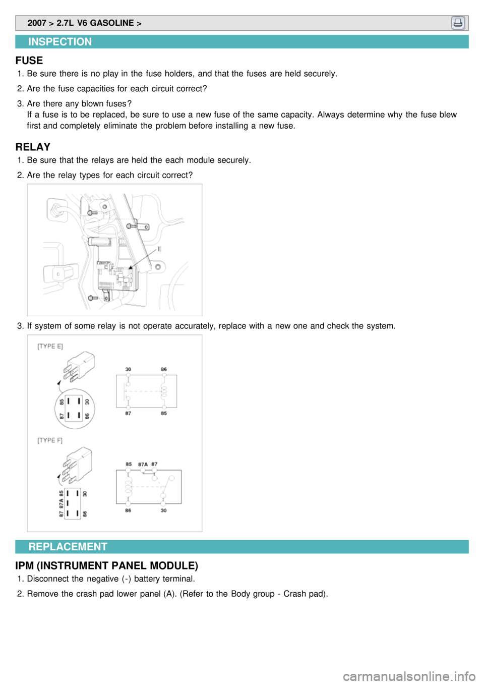
INSPECTION
FUSE
1. Be sure there is no play in the fuse holders, and that the fuses are held securely.
2. Are the fuse capacities for each circuit correct?
3. Are there any blown fuses ?
If a fuse is to be replaced, be sure to use a new fuse of the same capacity. Always determine why the fuse blew
first and completely eliminate the problem before installing a new fuse.
RELAY
1.Be sure that the relays are held the each module securely.
2. Are the relay types for each circuit correct?
Page 1292 of 1575
3.If system of some relay is not operate accurately, replace with a new one and check the system.
REPLACEMENT
FAM (FRONT AREA MODULE)
1. Disconnect the negative ( - ) battery terminal.
2. Remove the FAM cover of engine room.
3. Remove the FAM connectors (2EA) (A) and battery terminal nut (1EA) (B).
4.Remove FAM mounting bolts (3EA) (A) and remove the FAM (B) from splash shield (C).
5.Disconnect the connector from splash shield.
6. Installation is the reverse of removal.
Page 1293 of 1575
Relay Box
(Passenger Compartment)
Page 1298 of 1575
2007 > 2.7L V6 GASOLINE >
INSPECTION
FUSE
1. Be sure there is no play in the fuse holders, and that the fuses are held securely.
2. Are the fuse capacities for each circuit correct?
3. Are there any blown fuses ?
If a fuse is to be replaced, be sure to use a new fuse of the same capacity. Always determine why the fuse blew
first and completely eliminate the problem before installing a new fuse.
RELAY
1.Be sure that the relays are held the each module securely.
2. Are the relay types for each circuit correct?
3.If system of some relay is not operate accurately, replace with a new one and check the system.
REPLACEMENT
IPM (INSTRUMENT PANEL MODULE)
1. Disconnect the negative ( - ) battery terminal.
2. Remove the crash pad lower panel (A). (Refer to the Body group - Crash pad).
Page 1300 of 1575
ICM
(Integrated Circuit Module) Relay Box
Page 1301 of 1575
2007 > 2.7L V6 GASOLINE >
DESCRIPTION
The ICM (Integrated circuit module) relay (A) is united with many kinds of relays and installed side of the in - panel
module.
Page 1302 of 1575

2007 > 2.7L V6 GASOLINE >
INSPECTION
FRONT BLOWER
Check for continuity between the terminals. 1. There should be continuity between the No.1 in the ICM- A and No.10 in the ICM- B terminals when power and
ground are connected to the No.7 in the ICM- A and No.13 terminals in the ICM- B terminals.
2. There should be no continuity between the No.1 in the ICM- A and No.10 terminals in the ICM- B terminals when
power is disconnected.
REAR BLOWER
Check for continuity between the terminals.
1. There should be continuity between the No.4 in the ICM- A and No.12 in the ICM- B terminals when power and
ground are connected to the No.2 in the ICM- A and No.14 terminals in the ICM- B terminals.
2. There should be no continuity between the No.4 in the ICM- A and No.12 in the ICM- B terminals when power is
disconnected.
SEAT HEATER RELAYS
Check for continuity between the terminals.
1. There should be continuity between the No.9 and No.6 terminals when power and ground are connected to the
No.7 and No.8 terminals in the ICM- B.
2. There should be no continuity between the No.9 and No.6 terminals when power is disconnected.
KEY INTERLOCK
Check for continuity between the terminals.
1. There should be continuity between the No.2 and No.3 terminals when power and ground are connected to the
No.4 and No.5 terminals in the ICM- B.
2. There should be no continuity between the No.2 and No.3 terminals when power is disconnected.


