Rear Area Module KIA CARNIVAL 2007 Workshop Manual
[x] Cancel search | Manufacturer: KIA, Model Year: 2007, Model line: CARNIVAL, Model: KIA CARNIVAL 2007Pages: 1575, PDF Size: 44.86 MB
Page 1211 of 1575
2007 > 2.7L V6 GASOLINE >
DESCRIPTION
All modules are linked a low speed CAN network.
The input information for the modules is coming from both the CAN network and the hardware components
(actuatorsand sensors).
a. FAM (Front Area Module)
a. Headlamp low/high beam control (with DRL)
b. Park lamp control
c. Front fog lamp control
d. Front turn signal lamp control
e. Windshield wiper control
f. Windshield deicer
g. Diagnostics
b. IPM (In - Panel Module)
a. RKE (Remote Keyless Control)
b. VAS (Voice Alarm System)
c. Ignition key hole illumination
d. Switch indicators control
e. Panel light control
f. Seat belt warning
g. Auto light/DRL control (Logic)
h. Windshield/Rear wiper control (Logic)
i. Turn and Hazard lamp control (Logic)
j. Central door lock (Logic)
k. Windshield deicer timer
l. Rear glass defog timer
m. Gateway for ISO- 9141 (K- Line)
c. RAM (Rear Area Module)
a. Tail lamp control
b. Turn and Hazard lamp control
c. Back up lamp control
d. Rea fog lamp control
e. Stop lamp outage detection
f. Sliding door power window/Quarter glass control
g. Room lamp control
h. Rear wiper control
i. Rear glass defog
j. Fuel filler door open solenoid control
d. ADM (Assist Drive Module)
e. DDM (Driver Drive Module)
MODULE INTRODUCTION
FAM/IPM/RAM consists of a power board and an electronic board. The power board contains circuit protection devices
and switching devices. The electronic board uses Intelligent Power Switching (IPS) for HS/LS load control, logic
functions and CAN/K- Line communication. The power board and electronic board are connected with pin blocks for
the Front Area Module (FAM) and VCD (Variable Connection Displacement) for the In- Panel Module (IPM) and the
Rear Area Module (RAM).
Page 1218 of 1575
b.When the multifunction switch is not in postion headlamps turned on or autolight
c. 20 mn after the driver door is open
d. 20mn after IGN leaves the positions RUN to ACC or OFF
e. If IPM receives RKE "LOCK" command two times
3. Escort function enables only "Head Lamp Low Beam", so Park/Tail lamp should be turned off when driver door is
opened at key out (Battery Saver function).
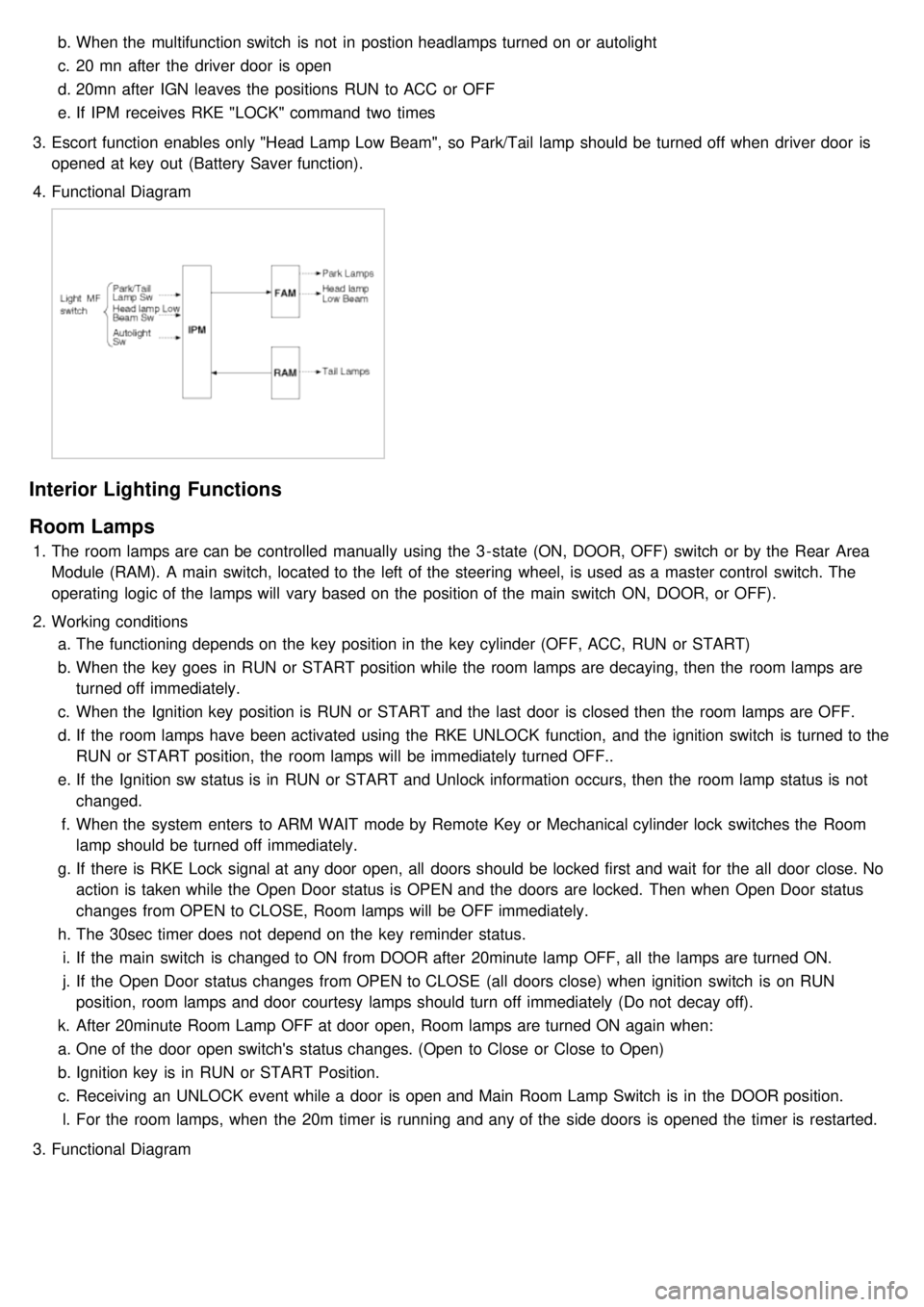
4. Functional Diagram
Interior Lighting Functions
Room Lamps
1.The room lamps are can be controlled manually using the 3 - state (ON, DOOR, OFF) switch or by the Rear Area
Module (RAM). A main switch, located to the left of the steering wheel, is used as a master control switch. The
operating logic of the lamps will vary based on the position of the main switch ON, DOOR, or OFF).
2. Working conditions
a. The functioning depends on the key position in the key cylinder (OFF, ACC, RUN or START)
b. When the key goes in RUN or START position while the room lamps are decaying, then the room lamps are
turned off immediately.
c. When the Ignition key position is RUN or START and the last door is closed then the room lamps are OFF.
d. If the room lamps have been activated using the RKE UNLOCK function, and the ignition switch is turned to the
RUN or START position, the room lamps will be immediately turned OFF..
e. If the Ignition sw status is in RUN or START and Unlock information occurs, then the room lamp status is not
changed.
f. When the system enters to ARM WAIT mode by Remote Key or Mechanical cylinder lock switches the Room
lamp should be turned off immediately.
g. If there is RKE Lock signal at any door open, all doors should be locked first and wait for the all door close. No
action is taken while the Open Door status is OPEN and the doors are locked. Then when Open Door status
changes from OPEN to CLOSE, Room lamps will be OFF immediately.
h. The 30sec timer does not depend on the key reminder status.
i. If the main switch is changed to ON from DOOR after 20minute lamp OFF, all the lamps are turned ON.
j. If the Open Door status changes from OPEN to CLOSE (all doors close) when ignition switch is on RUN
position, room lamps and door courtesy lamps should turn off immediately (Do not decay off).
k. After 20minute Room Lamp OFF at door open, Room lamps are turned ON again when:
a. One of the door open switch's status changes. (Open to Close or Close to Open)
b. Ignition key is in RUN or START Position.
c. Receiving an UNLOCK event while a door is open and Main Room Lamp Switch is in the DOOR position.
l. For the room lamps, when the 20m timer is running and any of the side doors is opened the timer is restarted.
3. Functional Diagram
Page 1219 of 1575
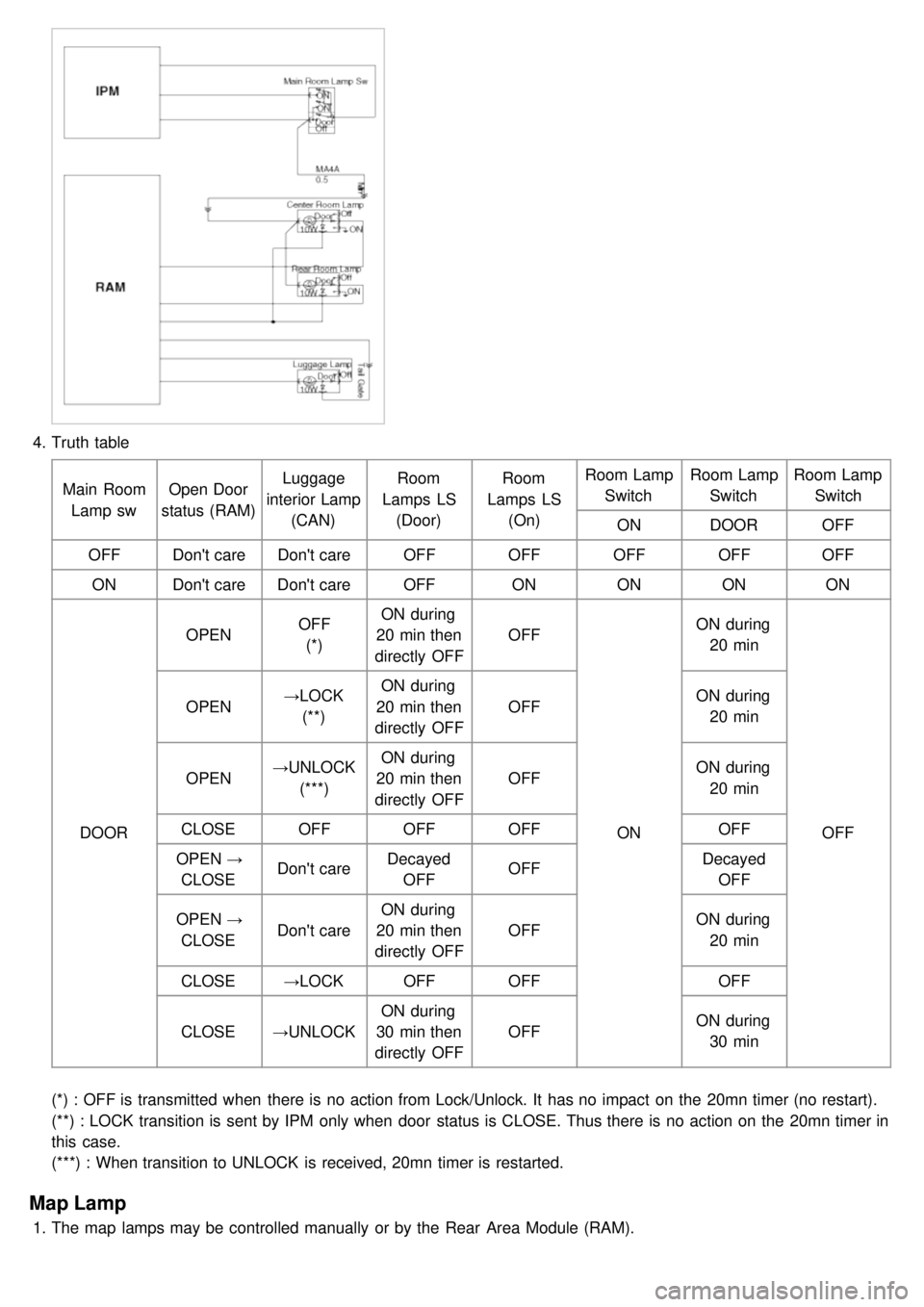
4.Truth table
Main RoomLamp sw Open Door
status (RAM) Luggage
interior Lamp (CAN) Room
Lamps LS (Door) Room
Lamps LS (On) Room Lamp
Switch Room Lamp
Switch Room Lamp
Switch
ON DOOR OFF
OFF Don't care Don't care OFFOFFOFFOFFOFF
ON Don't care Don't care OFFONONONON
DOOR OPEN
OFF
(*) ON during
20 min then
directly OFF OFF
ONON during
20 min
OFF
OPEN
→LOCK
(**) ON during
20 min then
directly OFF OFF
ON during
20 min
OPEN →UNLOCK
(***) ON during
20 min then
directly OFF OFF
ON during
20 min
CLOSE OFFOFFOFF OFF
OPEN →
CLOSE Don't care
Decayed
OFF OFF
Decayed
OFF
OPEN →
CLOSE Don't care ON during
20 min then
directly OFF OFF
ON during
20 min
CLOSE →LOCK OFFOFF OFF
CLOSE →UNLOCK ON during
30 min then
directly OFF OFF
ON during
30 min
(*) : OFF is transmitted when there is no action from Lock/Unlock. It has no impact on the 20mn timer (no restart).
(**) : LOCK transition is sent by IPM only when door status is CLOSE. Thus there is no action on the 20mn timer in
this case.
(***) : When transition to UNLOCK is received, 20mn timer is restarted.
Map Lamp
1. The map lamps may be controlled manually or by the Rear Area Module (RAM).
Page 1227 of 1575

Easy Access
1.Description
The easy access function permits automatic rearward movement of the driver seat when the key is removed from
the cylinder. Automatic forward movement of the driver seat will take place when the key is inserted into the
cylinder. This function will be enabled on IMS equipped vehicles when the AUTO button is pressed.
Inhibit Switch should be in P- Position for the Easy Access operation.
2. Functional Diagram
Driver Information
Cluster Indicators
1.The instument cluster indicators listed below are controlled by the In- Panel Module (IPM), Front Area Module
(FAM), or Rear Area Module (RAM) as applicable.
These indicators are:
a. Gearbox status
b. Oil pressure
c. Sediment fuel filter
d. Vacuum
e. Brake fluid
f. Washer fluid
g. Seat belt
h. Park brake
i. Charging voltage
j. Turn indicators
k. High beam
l. Front fog
m. Doors open
n. Tailgate open
o. Stop lamp failure front and rear
2. Functional Diagram
Page 1241 of 1575
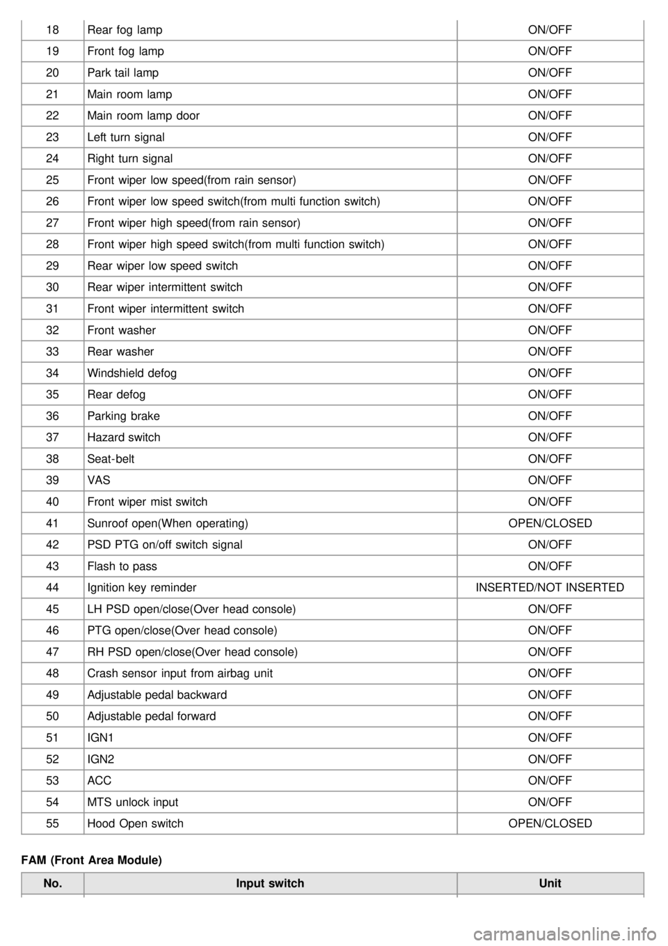
18Rear fog lamp ON/OFF
19 Front fog lamp ON/OFF
20 Park tail lamp ON/OFF
21 Main room lamp ON/OFF
22 Main room lamp door ON/OFF
23 Left turn signal ON/OFF
24 Right turn signal ON/OFF
25 Front wiper low speed(from rain sensor) ON/OFF
26 Front wiper low speed switch(from multi function switch) ON/OFF
27 Front wiper high speed(from rain sensor) ON/OFF
28 Front wiper high speed switch(from multi function switch) ON/OFF
29 Rear wiper low speed switch ON/OFF
30 Rear wiper intermittent switch ON/OFF
31 Front wiper intermittent switch ON/OFF
32 Front washer ON/OFF
33 Rear washer ON/OFF
34 Windshield defog ON/OFF
35 Rear defog ON/OFF
36 Parking brake ON/OFF
37 Hazard switch ON/OFF
38 Seat- belt ON/OFF
39 VAS ON/OFF
40 Front wiper mist switch ON/OFF
41 Sunroof open(When operating) OPEN/CLOSED
42 PSD PTG on/off switch signal ON/OFF
43 Flash to pass ON/OFF
44 Ignition key reminder INSERTED/NOT INSERTED
45 LH PSD open/close(Over head console) ON/OFF
46 PTG open/close(Over head console) ON/OFF
47 RH PSD open/close(Over head console) ON/OFF
48 Crash sensor input from airbag unit ON/OFF
49 Adjustable pedal backward ON/OFF
50 Adjustable pedal forward ON/OFF
51 IGN1 ON/OFF
52 IGN2 ON/OFF
53 ACC ON/OFF
54 MTS unlock input ON/OFF
55 Hood Open switch OPEN/CLOSED
FAM (Front Area Module) No. Input switch Unit
Page 1242 of 1575
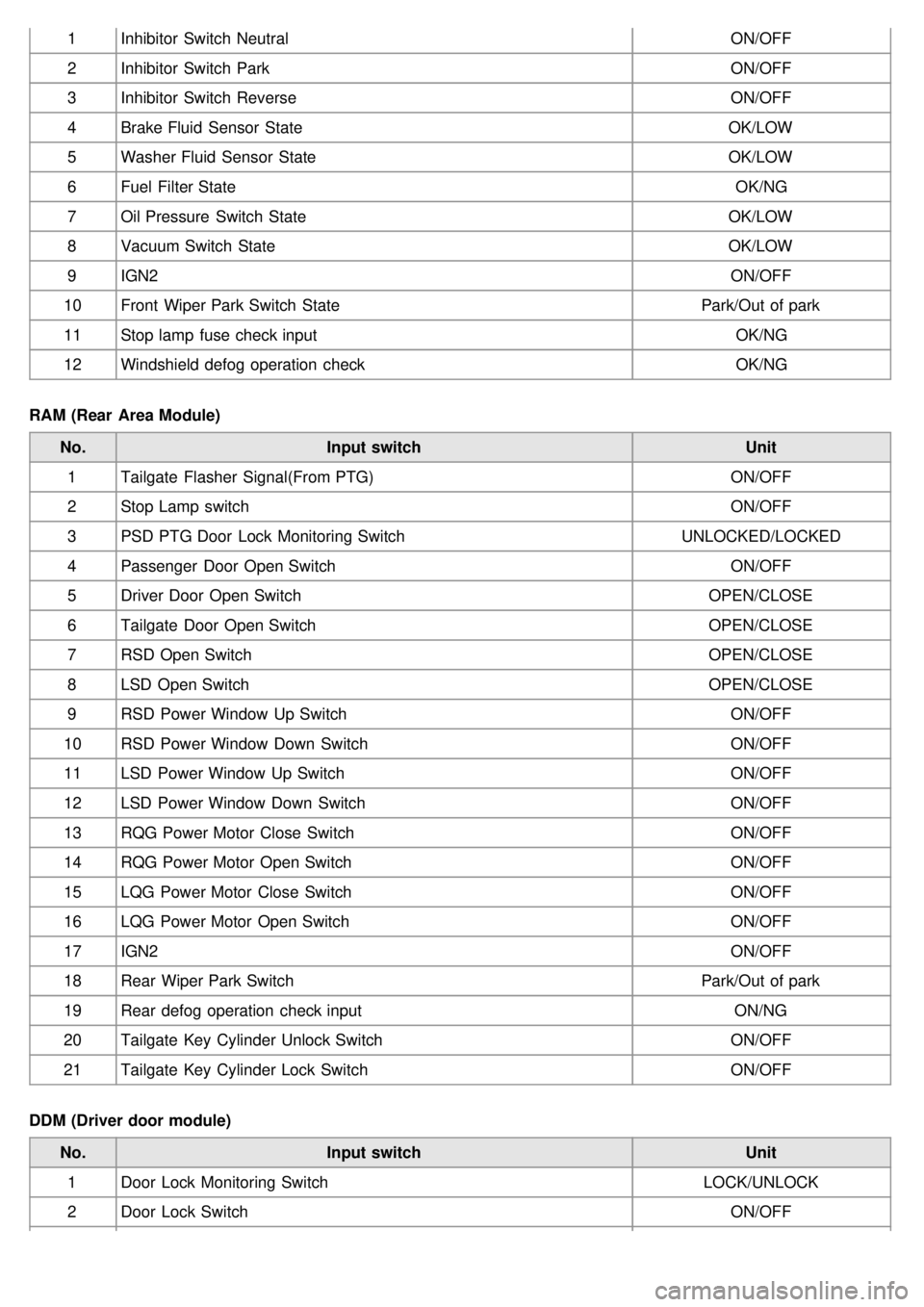
1Inhibitor Switch Neutral ON/OFF
2 Inhibitor Switch Park ON/OFF
3 Inhibitor Switch Reverse ON/OFF
4 Brake Fluid Sensor State OK/LOW
5 Washer Fluid Sensor State OK/LOW
6 Fuel Filter State OK/NG
7 Oil Pressure Switch State OK/LOW
8 Vacuum Switch State OK/LOW
9 IGN2 ON/OFF
10 Front Wiper Park Switch State Park/Out of park
11 Stop lamp fuse check input OK/NG
12 Windshield defog operation check OK/NG
RAM (Rear Area Module) No. Input switch Unit
1 Tailgate Flasher Signal(From PTG) ON/OFF
2 Stop Lamp switch ON/OFF
3 PSD PTG Door Lock Monitoring Switch UNLOCKED/LOCKED
4 Passenger Door Open Switch ON/OFF
5 Driver Door Open Switch OPEN/CLOSE
6 Tailgate Door Open Switch OPEN/CLOSE
7 RSD Open Switch OPEN/CLOSE
8 LSD Open Switch OPEN/CLOSE
9 RSD Power Window Up Switch ON/OFF
10 RSD Power Window Down Switch ON/OFF
11 LSD Power Window Up Switch ON/OFF
12 LSD Power Window Down Switch ON/OFF
13 RQG Power Motor Close Switch ON/OFF
14 RQG Power Motor Open Switch ON/OFF
15 LQG Power Motor Close Switch ON/OFF
16 LQG Power Motor Open Switch ON/OFF
17 IGN2 ON/OFF
18 Rear Wiper Park Switch Park/Out of park
19 Rear defog operation check input ON/NG
20 Tailgate Key Cylinder Unlock Switch ON/OFF
21 Tailgate Key Cylinder Lock Switch ON/OFF
DDM (Driver door module) No. Input switch Unit
1 Door Lock Monitoring Switch LOCK/UNLOCK
2 Door Lock Switch ON/OFF
Page 1252 of 1575

4.Installation is the reverse of removal.
FAM (Front Area Module)
1.Disconnect the negative ( - ) battery terminal.
2. Remove the FAM cover from the engine room.
3. Remove the 2 FAM connectors(A) and battery terminal nut(B).
4.Remove the IPM(B) from the splesh shield(C) after loosening the 3 IPM mounting bolts(A) and the IPM mounting
clip.
5.Disconnect the connector from the splesh shield.
6. Installation is the reverse of removal.
RAM (Rear Area Module)
1.Disconnect the negative ( - ) battery terminal.
2. Remove the left luggage side trim
(Refer to the Body group - interior trim)
3. Remove the RAM(A) after loosening the 7 connectors and the 3 RAM mounting bolts(A).
Page 1295 of 1575
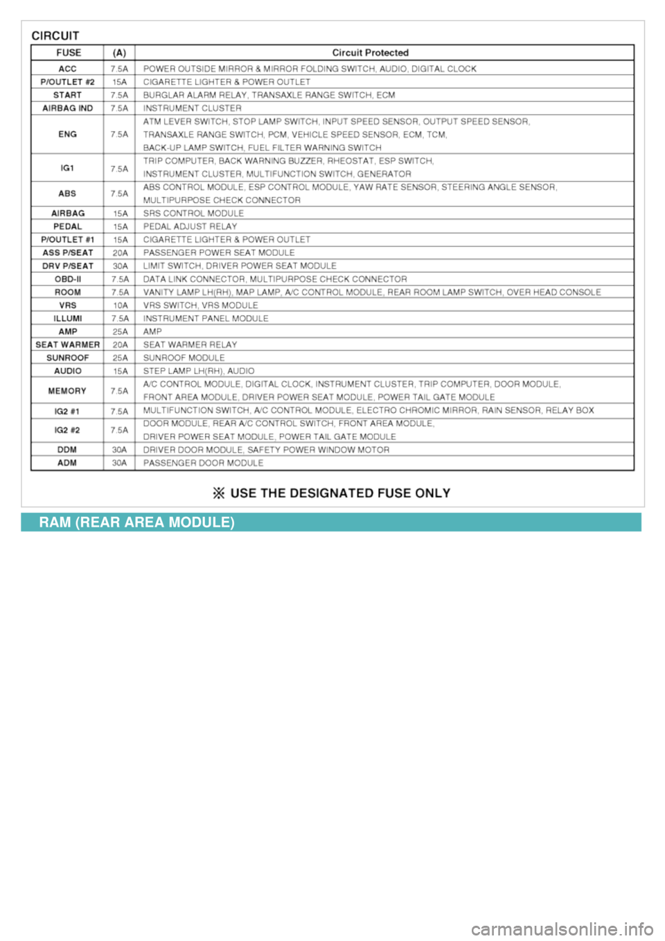
RAM (REAR AREA MODULE)
Page 1338 of 1575

2007 > 2.7L V6 GASOLINE >
INSPECTION
SLIDING DOOR MOTOR INSPECTION
1. It will be able to diagnose defects of PSD motor with scan tool quickly.
2. Select model and menu(BCM).
3.Select "rear area module(RAM)".
4.Select the "Actuation test" and "PSD open/close" to operate tailgate motor.
5.Replace the drive unit, if actuator operates abnormal.
DRIVE UNIT CLUTCH INSPECTION
1.Check the power sliding door control module input/output value by using the diagnostic tool. If the operation of
power sliding control module is abnormal, replace power sliding door drive unit.
2. When checking the clutch operation, select a vehicle type and "POWER SLIDING/TAILGATE" menu.
Page 1355 of 1575
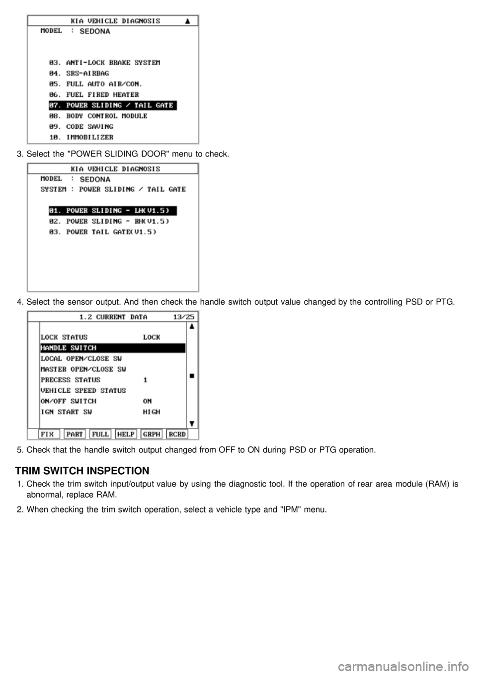
3.Select the "POWER SLIDING DOOR" menu to check.
4.Select the sensor output. And then check the handle switch output value changed by the controlling PSD or PTG.
5.Check that the handle switch output changed from OFF to ON during PSD or PTG operation.
TRIM SWITCH INSPECTION
1.Check the trim switch input/output value by using the diagnostic tool. If the operation of rear area module (RAM) is
abnormal, replace RAM.
2. When checking the trim switch operation, select a vehicle type and "IPM" menu.