KIA Opirus 2004 1.G Owner's Manual
Manufacturer: KIA, Model Year: 2004, Model line: Opirus, Model: KIA Opirus 2004 1.GPages: 296, PDF Size: 29.34 MB
Page 211 of 296
525
Driving tips
1
2
3
4
5
6
7
8
9
6. Return to the vehicle and firmlypress and release the pro-
grammed HomeLink button up to
three times. The rolling code
equipped device should now rec-
ognize the HomeLink signal and
activate when the HomeLink but-
ton is pressed. The remaining two
buttons may now be programmed
if this has not previously been
done. Refer to the “Programming”
portion of this text.
Operating HomeLink To operate, simply press the pro-
grammed HomeLink button.
Activation will now occur for the
trained product (garage door, securi-
ty system, entry door lock, estate
gate, or home or office lighting). For
convenience, the hand-held trans-
mitter of the device may also be used
at any time. The HomeLink Wireless
Controls System (once programmed)
or the original hand-held transmitter
may be used to activate the device
(e.g. garage door, entry door lock,
etc.). In the event that there are still
programming difficulties, contact
HomeLink at 1-800-355-3515 or on
the internet at www.homelink.com.
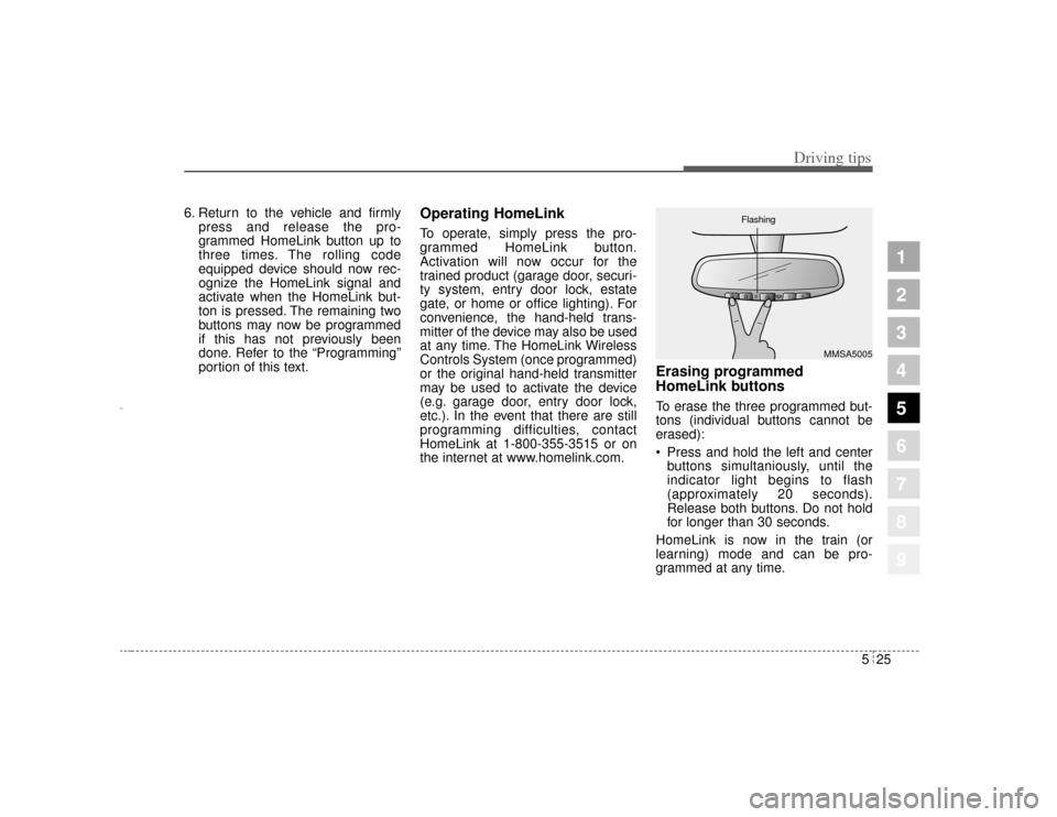
Erasing programmed
HomeLink buttonsTo erase the three programmed but-
tons (individual buttons cannot be
erased):
Press and hold the left and centerbuttons simultaniously, until the
indicator light begins to flash
(approximately 20 seconds).
Release both buttons. Do not hold
for longer than 30 seconds.
HomeLink is now in the train (or
learning) mode and can be pro-
grammed at any time.
MMSA5005
Flashing
Opirus CAN 5-1.qxd 7/8/03 2:21 PM Page 25
Page 212 of 296
Driving tips26
5
1
2
3
4
5
6
7
8
9
Reprogramming a single
HomeLink buttonTo program a device to HomeLink
using a HomeLink button previously
trained, follow these steps:
1. Press and hold the desired
HomeLink button. Do NOT release
until step 4 has been completed.
2. When the indicator light begins to flash slowly (after 20 seconds),
position the hand-held transmitter
3 ~ 7 cm away from the HomeLink
surface.
3. Press and hold the hand-held transmitter button (or press and
“cycle” - as described in
“Canadian Programming” above).
4. The HomeLink indicator light will flash, first slowly and then rapidly.
When the indicator light begins to
flash rapidly, release both buttons.
The previous device has now been
erased and the new device can be
activated by pushing the HomeLink
button that has just been pro-
grammed. This procedure will not
affect any other programmed
HomeLink buttons.
Gate operator programming &
canadian programmingDuring programming, your hand-held
transmitter may automatically stop
transmitting. Continue to press and
hold the HomeLink button (note
steps 2 through 4 in the
“Programming” portion of this text)
while you press and re-press
(“cycle”) your handheld transmitter
every two seconds until the frequen-
cy signal has been learned. The indi-
cator light will flash slowly and then
rapidly after several seconds upon
successful training.✽ ✽ NOTICEIf programming a garage door
opener or gate, it is advised to
unplug the device during the
“cycling” process to prevent possi-
ble motor burn-up.
AccessoriesIf you would like additional informa-
tion on the HomeLink Wireless
Control System, HomeLink compati-
ble products, or to purchase other
accessories such as the HomeLink®
Lighting Package, please contact
HomeLink at 1-800-355-3515 or on
the internet at www.homelink.com.
This device complies with FCC rules
part 15. Operation is subject to the
following two conditions:
(1) This device may not cause harm-
ful interference.
(2) This device must accept any
interference that may be received
including interference that may
cause undesired operation.
Opirus CAN 5-1.qxd 7/8/03 2:21 PM Page 26
Page 213 of 296
527
Driving tips
1
2
3
4
5
6
7
8
9
WARNING
The transmitter has been tested
and complies with FCC and
DOC/MDC rules. Changes or
modifications not expressly
approved by the party responsi-
ble for compliance could void
the user’s authority to operate
the device.
IC: 4112104541A Gentex
MODEL/FCC ID: NZLSTDHL3
Opirus CAN 5-1.qxd 7/8/03 2:21 PM Page 27
Page 214 of 296
1
2
3
4
5
6
7
8
91
2
3
4
5
6
7
8
9
Road warning / 6-2
Overheating / 6-3
Emergency starting / 6-4
Electrical circuit protection / 6-7
Towing / 6-15
If you have a flat tire / 6-20
In case of an emergency
Opirus CAN 6-1.qxd 7/8/03 2:22 PM Page 1
Page 215 of 296
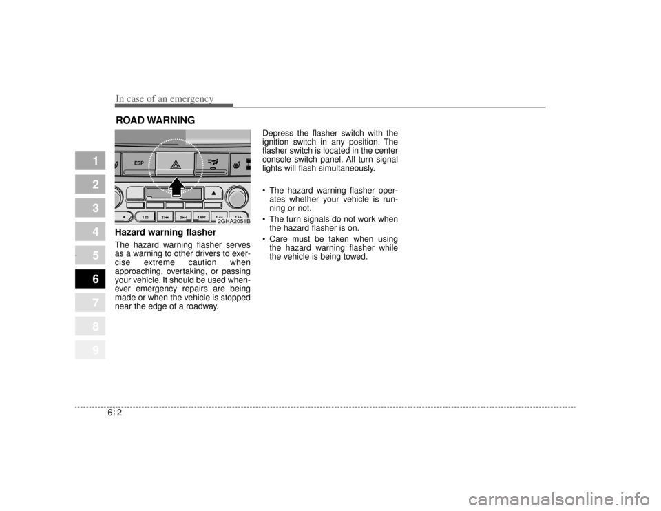
In case of an emergency26ROAD WARNING Hazard warning flasher The hazard warning flasher serves
as a warning to other drivers to exer-
cise extreme caution when
approaching, overtaking, or passing
your vehicle. It should be used when-
ever emergency repairs are being
made or when the vehicle is stopped
near the edge of a roadway.Depress the flasher switch with the
ignition switch in any position. The
flasher switch is located in the center
console switch panel. All turn signal
lights will flash simultaneously.
• The hazard warning flasher oper-
ates whether your vehicle is run-
ning or not.
The turn signals do not work when the hazard flasher is on.
Care must be taken when using the hazard warning flasher while
the vehicle is being towed.
1
2
3
4
5
6
7
8
9
ESP
2GHA2051B
Opirus CAN 6-1.qxd 7/8/03 2:22 PM Page 2
Page 216 of 296
63
In case of an emergency
OVERHEATING If your temperature gauge indicates
overheating, if you experience a loss
of power, or if you hear a loud knock-
ing or pinging noise, the engine has
probably overheated. Should any of
these symptoms occur, use the fol-
lowing procedure:
1. Turn on the hazard warning flash-er, then drive to the nearest safe
location and stop your vehicle; set
the automatic transaxle in P (Park)
and apply the parking brake.
2. Make sure the air conditioner is off.
3. If coolant or steam is boiling out of the radiator, stop the engine and
call an Authorized Kia Dealer for
assistance. If coolant is not boiling out, allow
the engine to idle and open the
hood to permit the engine to cool
gradually.
If the temperature does not go
down with the engine idling, stop
the engine and allow sufficient
time for it to cool.
4. The coolant level should then be checked. If the level in the reser-
voir is low, look for leaks at the
radiator hoses and connections,
heater hoses and connections,
radiator, and water pump. If you
find a major leak or another prob-
lem that may have caused the
engine to overheat, do not operate
the engine until it has been cor-
rected. Call an Authorized Kia
Dealer for assistance. If you do not
find a leak or other problem, care-
fully add coolant to the reservoir.
If the engine frequently overheats,have the cooling system checkedand repaired by an Authorized KiaDealer.
1
2
3
4
5
6
7
8
9
WARNING
- Removing
radiator cap
Do not remove the radiator cap
when the engine and radiator
are hot. Scalding hot coolant
and steam may blow out under
pressure. This could cause seri-
ous injury.
Opirus CAN 6-1.qxd 7/8/03 2:22 PM Page 3
Page 217 of 296
In case of an emergency46EMERGENCY STARTING Jump starting Jump starting can be dangerous if
done incorrectly. Therefore, to avoid
harm to yourself or damage to your
vehicle or battery, follow the jump
starting procedures listed on page
6-6. If in doubt, we strongly recom-
mend that you have a competent
technician or towing service jump
start your vehicle.
✽ ✽NOTICEUse only a 12-volt jumper system.
You can damage a 12-volt starting
motor, ignition system, and other
electrical parts beyond repair by use
of a 24-volt power supply (either two
12-volt batteries in series or a 24-
volt motor generator set).
1
2
3
4
5
6
7
8
9
WARNING
- Battery
• Keep all flames or sparks away from the battery. The bat-
tery produces hydrogen gas
which may explode if exposed
to flame or sparks.
Do not attempt to jump start the vehicle if the discharged
battery is frozen or if the elec-
trolyte level is low; the battery
may rupture or explode.
WARNING
- Battery
Never attempt to check the elec-
trolyte level of the battery as
this may cause the battery to
rupture or explode causing seri-
ous injury.
Opirus CAN 6-1.qxd 7/8/03 2:22 PM Page 4
Page 218 of 296
65
In case of an emergency
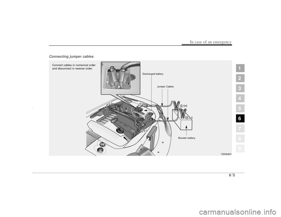
Connecting jumper cables
1
2
3
4
5
6
7
8
9
1GHA401
Connect cables in numerical order
and disconnect in reverse order.
Discharged batteryJumper Cables
Booster battery
Opirus CAN 6-1.qxd 7/8/03 2:22 PM Page 5
Page 219 of 296
In case of an emergency66Jump starting procedure 1. Make sure the booster battery is12-volt and that its negative termi-
nal is grounded.
2. If the booster battery is in another vehicle, do not allow the vehicles
to touch.
3. Turn off all unnecessary electrical loads.
4. Connect the jumper cables in the exact sequence shown in the pre-
vious illustration. First connect one
end of a jumper cable to the posi-
tive terminal of the discharged bat-
tery (
➀), then connect the other
end to the positive terminal on the
booster battery (
➁). Proceed to
connect one end of the other
jumper cable to the negative ter-
minal of the booster battery (
➂),
then the other end to a solid, sta-
tionary, metallic point (for exam-
ple, the engine lifting bracket)
away from the battery (
➃). Do not
connect it to or near any part that
moves when the engine is
cranked. Do not connect the
jumper cable from the negative
terminal of the booster battery to
the negative terminal of the dis-
charged battery. Do not allow the jumper cables to
contact anything except the cor-
rect battery terminals or the cor-
rect ground. Do not lean over the
battery when making connections.
5. Start the engine of the vehicle with the booster battery and let it run at
2,000 rpm, then start the engine of
the vehicle with the discharged
battery.
If the cause of your battery discharg-ing is not apparent, you should haveyour vehicle checked by anAuthorized Kia Dealer.
Refer to illustration on page 6-5.
Push-starting Vehicles equipped with automatic
transaxle cannot be push-started.
Follow the directions in this section
for jump-starting.
1
2
3
4
5
6
7
8
9
CAUTION
Never tow a vehicle to start itbecause the sudden surge for-ward when the engine startscould cause a collision with thetow vehicle.
Opirus CAN 6-1.qxd 7/8/03 2:22 PM Page 6
Page 220 of 296
67
In case of an emergency
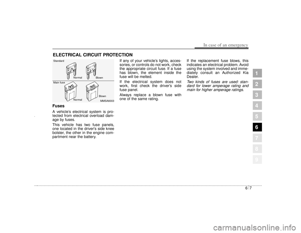
ELECTRICAL CIRCUIT PROTECTION Fuses A vehicle’s electrical system is pro-
tected from electrical overload dam-
age by fuses.
This vehicle has two fuse panels,
one located in the driver's side knee
bolster, the other in the engine com-
partment near the battery.If any of your vehicle’s lights, acces-
sories, or controls do not work, check
the appropriate circuit fuse. If a fuse
has blown, the element inside the
fuse will be melted.
If the electrical system does not
work, first check the driver’s side
fuse panel.
Always replace a blown fuse with
one of the same rating.
If the replacement fuse blows, this
indicates an electrical problem. Avoid
using the system involved and imme-
diately consult an Authorized Kia
Dealer.
Two kinds of fuses are used: stan-
dard for lower amperage rating andmain for higher amperage ratings.
1
2
3
4
5
6
7
8
9
MMSA6003
Standard
Main fuse
Normal Normal Blown
Blown
Opirus CAN 6-1.qxd 7/8/03 2:22 PM Page 7