ECU KIA OPTIMA 2020 Features and Functions Guide
[x] Cancel search | Manufacturer: KIA, Model Year: 2020, Model line: OPTIMA, Model: KIA OPTIMA 2020Pages: 591, PDF Size: 14.1 MB
Page 433 of 591

What to do in an emergency
14
6
IF YOU HAVE A FLAT TIRE
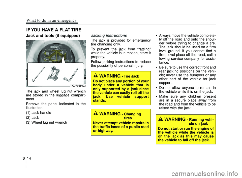
Jack and tools (if equipped)
The jack and wheel lug nut wrench
are stored in the luggage compart-
ment.
Remove the panel indicated in the
illustration.
(1) Jack handle
(2) Jack
(3) Wheel lug nut wrench
Jacking instructions
The jack is provided for emergency
tire changing only.
To prevent the jack from “rattling”
while the vehicle is in motion, store it
properly.
Follow jacking instructions to reduce
the possibility of personal injury. Always move the vehicle complete-
ly off the road and onto the shoul-
der before trying to change a tire.
The jack should be used on a firm
level ground. If you cannot find a
firm, level place off the road, call a
towing service company for assis-
tance.
Be sure to use the correct front and rear jacking positions on the vehi-
cle; never use the bumpers or any
other part of the vehicle for jack
support.
Do not allow anyone to remain in the vehicle while it is on the jack.
Make sure any children present are in a secure place away from
the road and from the vehicle to be
raised with the jack.
WARNING- Changing
tires
Never attempt vehicle repairs in
the traffic lanes of a public road
or highway.
OJF065003
WARNING- Tire Jack
Do not place any portion of your
body under a vehicle that is
only supported by a jack since
the vehicle can easily roll off the
jack. Use vehicle support
stands.
WARNING- Running vehi- cle on jack
Do not start or run the engine of
the vehicle while the vehicle is
on the jack as this may cause
the vehicle to fall off the jack.
JFa PE USA 6.qxp 5/15/2019 3:17 PM Page 14
Page 438 of 591

619
What to do in an emergency
Position the wrench as shown in the
drawing and tighten the wheel nuts.
Be sure the socket is seated com-
pletely over the nut. Do not stand on
the wrench handle or use an exten-
sion pipe over the wrench handle. Go
around the wheel, tightening every
nut following the numerical sequence
shown in the image until they are all
tight. Double-check each nut for
tightness. After changing wheels,
have an authorized Kia dealer tight-
en the wheel nuts to their proper
torque as soon as possible.
Wheel nut tightening torque:
79~94 lbf·ft (11~13 kgf·m)If you have a tire gauge, remove the
valve cap and check the air pressure.
If the pressure is lower than recom-
mended, drive slowly to the nearest
service station and inflate to the cor-
rect pressure. If it is too high, adjust
it until it is correct. Always reinstall
the valve cap after checking or
adjusting the tire pressure. If the cap
is not replaced, dust and dirt may get
into the tire valve and air may leak
from the tire. If you lose a valve cap,
buy another and install it as soon as
possible.
After you have changed the wheels,
always secure the flat tire in its place
and return the jack and tools to their
proper storage locations.
Note that most lug nuts do not have
metric threads. Be sure to use
extreme care in checking for thread
style before installing aftermarket lug
nuts or wheels. If in doubt, consult an
authorized Kia dealer.
CAUTION- Reusing lug
nuts
Make certain during wheelremoval that the same nuts thatwere removed are reinstalled -or, if replaced, that nuts withmetric threads and the samechamfer configuration are used.Your vehicle has metric threadson the wheel studs and nuts.Installation of a non-metricthread nut on a metric stud willnot secure the wheel to the hubproperly and will damage thestud so that it must be replaced.
OJF065009
JFa PE USA 6.qxp 5/15/2019 3:18 PM Page 19
Page 476 of 591

723
Maintenance
Vacuum crankcase ventilation
hoses
Inspect the surface of hoses for evi-
dence of heat and/or mechanical
damage. Hard and brittle rubber,
cracking, tears, cuts, abrasions, and
excessive swelling indicate deterio-
ration.
Pay particular attention to the hose
surfaces nearest to high heat
sources, such as the exhaust mani-
fold.
Inspect the hose routing to assure
that the hoses do not come in con-
tact with any heat source, sharp
edges or moving component which
might cause heat damage or
mechanical wear. Inspect all hose
connections, such as clamps and
couplings, to make sure they are
secure, and that no leaks are pres-
ent. Hoses should be replaced
immediately if there is any evidence
of deterioration or damage.
Air cleaner filter
A Genuine Kia air cleaner filter is rec-
ommended when the filter is replaced.
Spark plugs
Make sure to install new spark plugs
of the correct heat range.
Valve clearance (if equipped)
Inspect for excessive valve noise
and/or engine vibration and adjust if
necessary. An authorized Kia dealer
should perform this procedure.
Cooling system
Check the cooling system compo-
nents, such as the radiator, coolant
reservoir, hoses and connections for
leakage and damage. Replace any
damaged parts.
Coolant
The coolant should be changed at
the intervals specified in the mainte-
nance schedule.
Automatic transmission fluid
Automatic transmission fluid should
not be checked under normal usage
conditions.
But in severe conditions, the fluid
should be changed at an authorized
Kia dealer in accordance to the
scheduled maintenance at the begin-
ning of this chapter.
✽ ✽NOTICE
Automatic transmission fluid color
is usually red.
As the vehicle is driven, the auto-
matic transmission fluid will begin
to look darker.
This is normal, and you should not
judge the need to replace the fluid
based upon the changed color.
JFa PE USA 7.qxp 5/15/2019 3:12 PM Page 23
Page 486 of 591

733
Maintenance
Checking the parking brake
Check whether the stroke is within
specification when the parking brake
pedal is pressed with 66 lb, 294 N
(30 kg) of force. Also, the parking
brake alone should securely hold the
vehicle on a fairly steep grade. If the
stroke is more or less than specified,
have the parking brake adjusted by
an authorized Kia dealer.
Stroke : 6~7 notch
PARKING BRAKE
OJF055017
JFa PE USA 7.qxp 5/15/2019 3:13 PM Page 33
Page 495 of 591

Maintenance
42
7
BATTERY
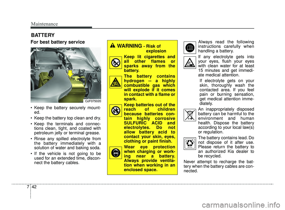
For best battery service
Keep the battery securely mount-
ed.
Keep the battery top clean and dry.
Keep the terminals and connec- tions clean, tight, and coated with
petroleum jelly or terminal grease.
Rinse any spilled electrolyte from the battery immediately with a
solution of water and baking soda.
If the vehicle is not going to be used for an extended time, discon-
nect the battery cables. Always read the following
instructions carefully when
handling a battery.
If any electrolyte gets into your eyes, flush your eyes
with clean water for at least
15 minutes and get immedi-
ate medical attention.
If electrolyte gets on your
skin, thoroughly wash the
contacted area. If you feel
pain or burning sensation,
get medical attention imme-
diately.
An inappropriately disposed battery can be harmful to the
environment and human
health. Dispose the battery
according to your local law(s)
or regulation.
The battery contains lead. Do
not dispose of it after use.
Please return the battery to
an authorized Kia dealer to
be recycled.
Never attempt to recharge the bat-
tery when the battery cables are con-
nected.
WARNING- Risk of explosion
Keep lit cigarettes and
all other flames or
sparks away from the
battery.
The battery contains hydrogen -- a highly
combustible gas which
will explode if it comes
in contact with a flame or
spark.
Keep batteries out of the reach of children
because batteries con-
tain highly corrosive
SULFURIC ACID and
electrolytes. Do not
allow battery acid to
contact your skin, eyes,
clothing or paint finish.
Wear eye protection when charging or work-
ing near a battery.
Always provide ventila-
tion when working in an
enclosed space.
OJF075020
JFa PE USA 7.qxp 5/15/2019 3:13 PM Page 42
Page 514 of 591

761
Maintenance
✽ ✽NOTICE
• When replacing a fuse, turn the
ignition “OFF” and turn off
switches of all electrical devices
then remove battery (-) terminal.
• The actual fuse/relay panel label may differ from equipped items.
WARNING- Electrical Fire
Always ensure replacements
fuses and relays are securely
fastened when installed. Failure
to do so can result in a vehicle
fire.
CAUTION
When replacing a blown fuse or relay, make sure the newfuse or relay fits tightly intothe clips. Failure to tightlyinstall the fuse or relay maycause damage to the wiringand electric systems.
Do not remove fuses, relays and terminals fastened withbolts or nuts. The fuses, relaysand terminals may not be fas-tened correctly which maycause vehicle damage.
CAUTION
Do not input any other objects except fuses or relays intofuse/relay terminals such as ascrewdriver or wiring. It maycause contact failure and sys-tem malfunction.
Do not plug in screwdrivers or aftermarket wiring into the ter-minal originally designed forfuse and relays only. The elec-trical system and wiring of thevehicle interior may be dam-aged or burned due to contactfailure.
If you directly connect the wire on the taillight or replacethe bulb which is over the reg-ulated capacity to install trail-ers etc., the inner junctionblock can get burned.
JFa PE USA 7.qxp 5/15/2019 3:14 PM Page 61
Page 515 of 591

Maintenance
62
7
✽ ✽
NOTICE- Remodeling
Prohibited
Do not rewire your vehicle in any
way as doing so may affect the per-
formance of several safety features
in your vehicle. Rewiring your vehi-
cle may also void your warranty and
cause you to be responsible for any
subsequent vehicle damage which
may result.
✽ ✽ NOTICE- Window tinting pre-
caution
Window tint (especially metallic
film) might cause communication
errors or poor radio reception, and
malfunctioning automatic lighting
system due to reflections from the
mirror tint inside the vehicle. The
solution used might also leak into
the electronic components, causing
malfunctions or damage.
Inner panel fuse replacement
1. Turn the ignition switch and all other switches off.
2. Open the fuse panel cover.
If the switch is located in the “OFF”
position, a caution indicator will be
displayed in the cluster.
To identify the location of a specific
fuse, please refer to the inside of the
fuse panel cover and the description
list in this section.
CAUTION
Visually inspect the battery cap to ensure it is securely closed.If the battery cap is not securelyclosed, moisture may enter thesystem and damage the electri-cal components.
WARNING
- Electrical wiring repairs
All electrical repairs should be
performed by authorized Kia
dealerships using approved Kia
parts. Using other wiring com-
ponents, especially when retro-
fitting AVN or theft alarm sys-
tem, remote engine control, car
phone or radio may cause vehi-
cle damage and increase the
risk of a vehicle fire.
OJF075022
JFa PE USA 7.qxp 5/15/2019 3:14 PM Page 62
Page 517 of 591

Maintenance
64
7
✽ ✽
NOTICE
If the vehicle is going to be unused
for over 1 month, set all switches to
OFF to prevent the batteries from
draining.
Engine compartment fuse
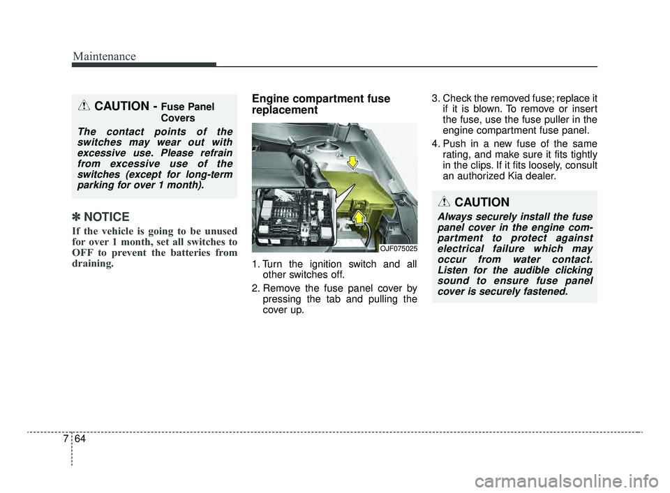
replacement
1. Turn the ignition switch and all
other switches off.
2. Remove the fuse panel cover by pressing the tab and pulling the
cover up. 3. Check the removed fuse; replace it
if it is blown. To remove or insert
the fuse, use the fuse puller in the
engine compartment fuse panel.
4. Push in a new fuse of the same rating, and make sure it fits tightly
in the clips. If it fits loosely, consult
an authorized Kia dealer.
OJF075025
CAUTION - Fuse Panel
Covers
The contact points of theswitches may wear out withexcessive use. Please refrainfrom excessive use of theswitches (except for long-termparking for over 1 month).
CAUTION
Always securely install the fusepanel cover in the engine com-partment to protect againstelectrical failure which mayoccur from water contact.Listen for the audible clickingsound to ensure fuse panelcover is securely fastened.
JFa PE USA 7.qxp 5/15/2019 3:14 PM Page 64
Page 518 of 591

765
Maintenance
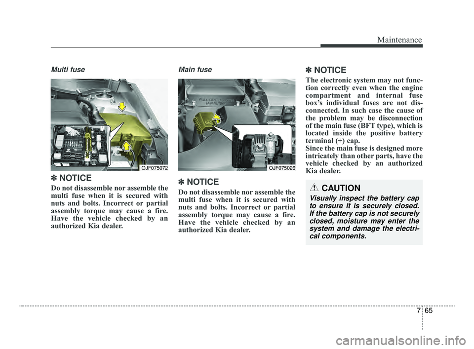
Multi fuse
✽ ✽NOTICE
Do not disassemble nor assemble the
multi fuse when it is secured with
nuts and bolts. Incorrect or partial
assembly torque may cause a fire.
Have the vehicle checked by an
authorized Kia dealer.
Main fuse
✽ ✽NOTICE
Do not disassemble nor assemble the
multi fuse when it is secured with
nuts and bolts. Incorrect or partial
assembly torque may cause a fire.
Have the vehicle checked by an
authorized Kia dealer.
✽ ✽NOTICE
The electronic system may not func-
tion correctly even when the engine
compartment and internal fuse
box’s individual fuses are not dis-
connected. In such case the cause of
the problem may be disconnection
of the main fuse (BFT type), which is
located inside the positive battery
terminal (+) cap.
Since the main fuse is designed more
intricately than other parts, have the
vehicle checked by an authorized
Kia dealer.
OJF075072OJF075026
CAUTION
Visually inspect the battery cap
to ensure it is securely closed.If the battery cap is not securelyclosed, moisture may enter thesystem and damage the electri-cal components.
JFa PE USA 7.qxp 5/15/2019 3:14 PM Page 65
Page 520 of 591

767
Maintenance
Fuse NameFuse ratingCircuit Protected
MODULE 710AAround View Unit, Front Air Ventilation Seat Control Module, Front Seat Warmer Control Module, Rear Seat
Warmer Control Module
MODULE 510A
A/C Control Module, Electro Chromic Mirror, Crash Pad Switch, Head Lamp LH/RH, Auto Head Lamp
Leveling Device Module, A/V & Navigation Head Unit, Fuel Lid & Trunk Open Switch, Shift Lever Indicator,
Driver IMS Module, Driver IMS Module, Front Air Ventilation Seat Control Module, Front Seat Warmer
Control Module, Rear Seat Warmer Control Module
MODULE 610ABCM, Smart Key Control Module
A/CON10AA/C Control Module, E/R Junction Block (Blower Relay)
START10A[W/O Smart Key & IMMO.] ICM Relay Box (Burglar Alarm Relay)
[With Smart Key / IMMO.] Transmission Range Switch, PCM (G4KH/G4KJ)
A/BAG15ASRS Control Module, Passenger Occupant Detection
MODULE 310ABCM, ATM Shift Lever, Stop Lamp Switch, DBL Unit, Keyboard, A/C Control Module
MODULE 410AConsole Switch, Blind Spot Detection Radar LH/RH, Smart Cruise Control Unit, AEB Module, Lane Keeping
Assist Module
INTERIOR LAMP10ATrunk Room Lamp, Ignition Key Ill. & Door Warning Switch, Glove Box Lamp, Driver/Passenger Smart Key
Outside Handle, Front Vanity Lamp Switch LH/RH, Overhead Console Lamp, Center Room Lamp, Center
Personal Lamp, Rear Personal Lamp LH/RH, Driver/Passenger Scuff Lamp
MDPS10AMDPS Unit (Column/Rack), Steering Angle Sensor
IG125APCB Block (Fuse - TCU 2, ABS 3, ECU 3, VACUUM PUMP 2)
MODULE 910AImmobilizer Module, Smart Key Control Module
Instrument panel (Driver’s side fuse panel)
JFa PE USA 7.qxp 5/15/2019 3:14 PM Page 67