ecu KIA Optima Hybrid 2011 3.G Owner's Guide
[x] Cancel search | Manufacturer: KIA, Model Year: 2011, Model line: Optima Hybrid, Model: KIA Optima Hybrid 2011 3.GPages: 394, PDF Size: 8.63 MB
Page 312 of 394
719
Maintenance
EXPLANATION OF SCHEDULED MAINTENANCE ITEMS
Engine oil and filter
The engine oil and filter should be
changed at the intervals specified in the
maintenance schedule. If the car is being
driven in severe conditions, more fre-
quent oil and filter changes are required.
Drive belts
Inspect all drive belts for evidence of
cuts, cracks, excessive wear or oil satu-
ration and replace if necessary. Drive
belts should be checked periodically for
proper tension and adjusted as neces-
sary.
Fuel filter
A clogged filter can limit the speed at
which the vehicle may be driven, damage
the emission system and cause multiple
issues such as hard starting. If an exces-
sive amount of foreign matter accumu-
lates in the fuel tank, the filter may
require replacement more frequently.
After installing a new filter, run the engine
for several minutes, and check for leaks
at the connections. Fuel filters should be
installed by an authorized Kia dealer.
Fuel lines, fuel hoses and con-
nections
Check the fuel lines, fuel hoses and con-
nections for leakage and damage. Have
an authorized Kia dealer replace any
damaged or leaking parts immediately.
Vapor hose and fuel filler cap
The vapor hose and fuel filler cap should
be inspected at those intervals specified
in the maintenance schedule. Make sure
that a new vapor hose or fuel filler cap is
correctly replaced.
Vacuum hose and crankcase ven-
tilation hoses
Inspect the surface of hoses for evidence
of heat and/or mechanical damage. Hard
and brittle rubber, cracking, tears, cuts,
abrasions, and excessive swelling indi-
cate deterioration. Particular attention
should be paid to examine those hose
surfaces nearest to high heat sources,
such as the exhaust manifold.
Inspect the hose routing to assure that
the hoses do not come in contact with
any heat source, sharp edges or moving
component which might cause heat dam-
age or mechanical wear. Inspect all hose
connections, such as clamps and cou-
plings, to make sure they are secure, and
that no leaks are present.
Hoses should be replaced immediately if
there is any evidence of deterioration or
damage.
Page 322 of 394
729
Maintenance
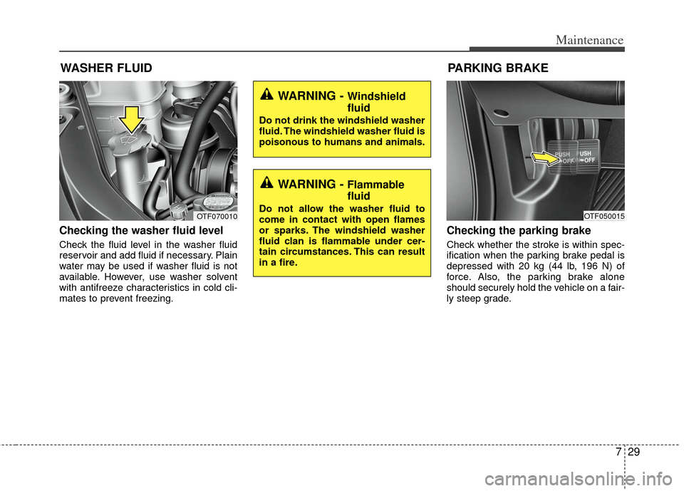
Checking the washer fluid level
Check the fluid level in the washer fluid
reservoir and add fluid if necessary. Plain
water may be used if washer fluid is not
available. However, use washer solvent
with antifreeze characteristics in cold cli-
mates to prevent freezing.
Checking the parking brake
Check whether the stroke is within spec-
ification when the parking brake pedal is
depressed with 20 kg (44 lb, 196 N) of
force. Also, the parking brake alone
should securely hold the vehicle on a fair-
ly steep grade.
WARNING - Windshield
fluid
Do not drink the windshield washer
fluid. The windshield washer fluid is
poisonous to humans and animals.
WARNING - Flammable
fluid
Do not allow the washer fluid to
come in contact with open flames
or sparks. The windshield washer
fluid clan is flammable under cer-
tain circumstances. This can result
in a fire.
WASHER FLUID
OTF070010
PARKING BRAKE
OTF050015
Page 328 of 394
735
Maintenance
BATTERY
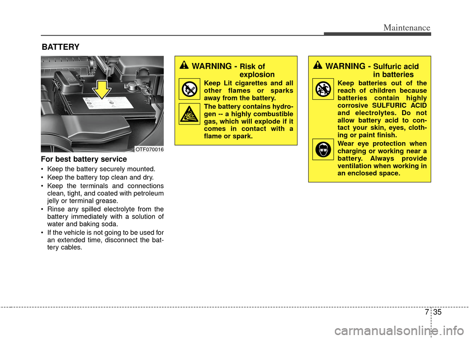
For best battery service
Keep the battery securely mounted.
Keep the battery top clean and dry.
Keep the terminals and connectionsclean, tight, and coated with petroleum
jelly or terminal grease.
Rinse any spilled electrolyte from the battery immediately with a solution of
water and baking soda.
If the vehicle is not going to be used for an extended time, disconnect the bat-
tery cables.
WARNING - Risk of
explosion
Keep Lit cigarettes and all
other flames or sparks
away from the battery.
The battery contains hydro-
gen -- a highly combustible
gas, which will explode if it
comes in contact with a
flame or spark.
WARNING - Sulfuric acid
in batteries
Keep batteries out of the
reach of children because
batteries contain highly
corrosive SULFURIC ACID
and electrolytes. Do not
allow battery acid to con-
tact your skin, eyes, cloth-
ing or paint finish.
Wear eye protection when charging or working near a
battery. Always provide
ventilation when working in
an enclosed space.
OTF070016
Page 346 of 394
753
Maintenance
✽
✽NOTICE
• If the memory fuse is pulled up from
the fuse panel, the warning chime,
audio, clock and interior lamps, etc.,
will not operate. Some items must be
reset after replacement. Refer to
“Battery” in this section.
• Even when the memory fuse is pulled up, the battery can still be discharged
by operation of the headlights or other
electrical devices.
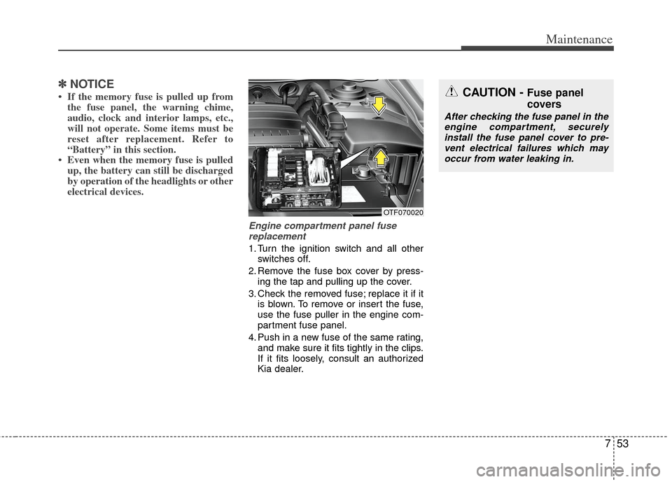
Engine compartment panel fuse
replacement
1. Turn the ignition switch and all other switches off.
2. Remove the fuse box cover by press- ing the tap and pulling up the cover.
3. Check the removed fuse; replace it if it is blown. To remove or insert the fuse,
use the fuse puller in the engine com-
partment fuse panel.
4. Push in a new fuse of the same rating, and make sure it fits tightly in the clips.
If it fits loosely, consult an authorized
Kia dealer.
CAUTION - Fuse panel
covers
After checking the fuse panel in theengine compartment, securely install the fuse panel cover to pre-vent electrical failures which mayoccur from water leaking in.
OTF070020
Page 350 of 394
757
Maintenance
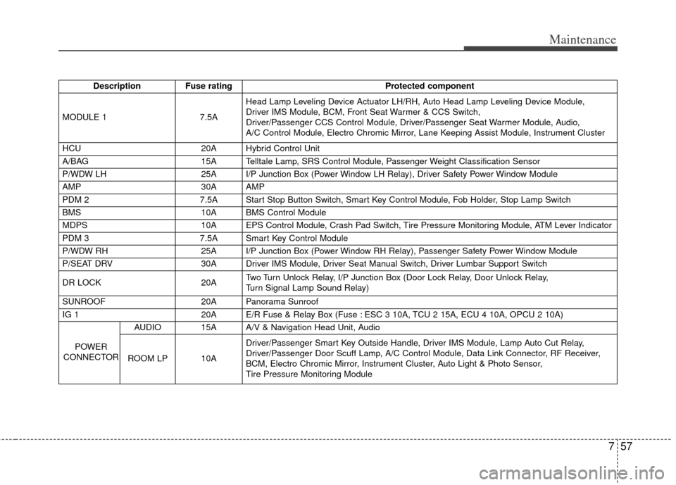
DescriptionFuse rating Protected component
MODULE 1 7.5AHead Lamp Leveling Device Actuator LH/RH, Auto Head Lamp Leveling Device Module,
Driver IMS Module, BCM, Front Seat Warmer & CCS Switch,
Driver/Passenger CCS Control Module, Driver/Passenger Seat Warmer Module, Audio,
A/C Control Module, Electro Chromic Mirror, Lane Keeping Assist Module, Instrument Cluster
HCU 20A Hybrid Control Unit
A/BAG 15A Telltale Lamp, SRS Control Module, Passenger Weight Classification Sensor
P/WDW LH 25A I/P Junction Box (Power Window LH Relay), Driver Safety Power Window Module
AMP 30A AMP
PDM 2 7.5A Start Stop Button Switch, Smart Key Control Module, Fob Holder, Stop Lamp Switch
BMS 10A BMS Control Module
MDPS 10A EPS Control Module, Crash Pad Switch, Tire Pressure Monitoring Module, ATM Lever Indicator
PDM 3 7.5A Smart Key Control Module
P/WDW RH 25A I/P Junction Box (Power Window RH Relay), Passenger Safety Power Window Module
P/SEAT DRV 30A Driver IMS Module, Driver Seat Manual Switch, Driver Lumbar Support Switch
DR LOCK 20ATwo Turn Unlock Relay, I/P Junction Box (Door Lock Relay, Door Unlock Relay,
Turn Signal Lamp Sound Relay)
SUNROOF 20A Panorama Sunroof
IG 1 20A E/R Fuse & Relay Box (Fuse : ESC 3 10A, TCU 2 15A, ECU 4 10A, OPCU 2 10A)
POWER
CONNECTOR AUDIO 15A A/V & Navigation Head Unit, Audio
ROOM LP 10A Driver/Passenger Smart Key Outside Handle, Driver IMS Module, Lamp Auto Cut Relay,
Driver/Passenger Door Scuff Lamp, A/C Control Module, Data Link Connector, RF Receiver,
BCM, Electro Chromic Mirror, Instrument Cluster, Auto Light & Photo Sensor,
Tire Pressure Monitoring Module
Page 352 of 394
759
Maintenance
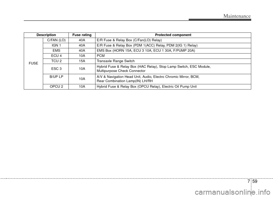
Description Fuse ratingProtected component
FUSE C/FAN (LO) 40A E/R Fuse & Relay Box (C/Fan(LO) Relay)
IGN 1 40A E/R Fuse & Relay Box (PDM 1(ACC) Relay, PDM 2(IG 1) Relay)
EMS 40A EMS Box (HORN 15A, ECU 3 10A, ECU 1 30A, F/PUMP 20A)
ECU 4 10A PCM TCU 2 15A Transaxle Range Switch
ESC 3 10A Hybrid Fuse & Relay Box (HAC Relay), Stop Lamp Switch, ESC Module,
Multipurpose Check Connector
B/UP LP 10AA/V & Navigation Head Unit, Audio, Electro Chromic Mirror, BCM,
Rear Combination Lamp(IN) LH/RH
OPCU 2 10A Hybrid Fuse & Relay Box (OPCU Relay), Electric Oil Pump Unit