sensor KIA Optima Hybrid 2014 3.G Owner's Guide
[x] Cancel search | Manufacturer: KIA, Model Year: 2014, Model line: Optima Hybrid, Model: KIA Optima Hybrid 2014 3.GPages: 474, PDF Size: 12.73 MB
Page 315 of 474
Driving your vehicle
38
5
If a vehicle is detected within the
boundary of the system, a warning
light will illuminate on the outside
rearview mirror.
If the detected vehicle is not in
detecting range, the warning will turn
off according to driving conditions. The second stage alarm will activate
when:
1.The first stage alert is on
2.The turn signal is on to change a
lane
When the second stage alert is acti-
vated, a warning light will blink on the
outside rearview mirror and a alarm
will sound.
If you move the turn signal switch to
the original position, the second
stage alert will be deactivated.
Detecting sensor
The sensors are located inside of the
rear bumper.
Always keep the rear bumper clean
for the system to work properly.
OTF054107
1st stage
OTF054108
2nd stage
OTFH054109
Page 316 of 474
539
Driving your vehicle
Warning message
The message will appear to notify
the driver if there are foreign sub-
stances on the rear bumper or it is
hot near the rear bumper. The light
on the switch and the system will
turn off automatically.
Remove the foreign matter on the
rear bumper.
If the system does not work normally
even though the foreign matter is
removed, take your vehicle to an
authorized Kia dealer and have the
system checked.If the system does not work properly,
a warning message will appear and
the light on the switch will turn off.
The system will turn off automatical-
ly.
Have your vehicle inspected by an
authorized Kia dealer.
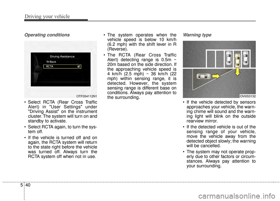
RCTA (Rear cross traffic alert)
When your vehicle moves backwards
from a parking position, the sensor
detects approaching vehicles to the
left or right side direction and gives
information to the driver.
OTF054104L
OTF054103L
OVI053131
Page 317 of 474
Driving your vehicle
40
5
Operating conditions
Select RCTA (Rear Cross Traffic
Alert) in "User Settings" under
"Driving Assist" on the instrument
cluster. The system will turn on and
standby to activate.
Select RCTA again, to turn the sys- tem off.
If the vehicle is turned off and on again, the RCTA system will return
to the state right before the vehicle
was turned off. Always turn the
RCTA system off when not in use. The system operates when the
vehicle speed is below 10 km/h
(6.2 mph) with the shift lever in R
(Reverse).
The RCTA (Rear Cross Traffic Alert) detecting range is 0.5m ~
20m based on the side direction. If
the approaching vehicle speed is
4 km/h (2.5 mph) ~ 36 km/h (22
mph) within sensing range, it is
detected. However, the system
sensing range is different base on
conditions. Always pay attention to
the surrounding.
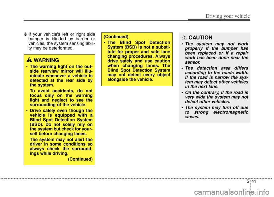
Warning type
If the vehicle detected by sensorsapproaches your vehicle, the warn-
ing chime will sound and the warn-
ing light will blink on the outside
rearview mirror.
If the detected vehicle is out of the sensing range of your vehicle,
move the vehicle away from the
detected object slowly; the warning
will be cancelled.
The system may not operate prop- erly due to other factors or circum-
stances. Always pay attention to
your surrounding.
OTF054112N1OVI053132
Page 318 of 474
541
Driving your vehicle
❈If your vehicle's left or right side
bumper is blinded by barrier or
vehicles, the system sensing abili-
ty may be deteriorated.
WARNING
The warning light on the out-
side rearview mirror will illu-
minate whenever a vehicle is
detected at the rear side by
the system.
To avoid accidents, do not
focus only on the warning
light and neglect to see the
surrounding of the vehicle.
Drive safely even though the vehicle is equipped with a
Blind Spot Detection System
(BSD). Do not solely rely on
the system but check for your-
self before changing lanes.
The system may not alert the
driver in some conditions so
always check the surround-
ings while driving.
(Continued)
(Continued)
The Blind Spot DetectionSystem (BSD) is not a substi-
tute for proper and safe lane
changing procedures. Always
drive safely and use caution
when changing lanes. The
Blind Spot Detection System
may not detect every object
alongside the vehicle.CAUTION
The system may not work properly if the bumper hasbeen replaced or if a repairwork has been done near thesensor.
The detection area differs according to the roads width.If the road is narrow the sys-tem may detect other vehiclesin the next lane.
On the contrary, if the road is very wide the system may notdetect other vehicles.
The system may turn off due to strong electromagneticwaves.
Page 319 of 474
Driving your vehicle
42
5
Non-operating condition
Driver's Attention
The driver must be cautious in the
below situations for the system may
not assist the driver and may not
work properly.
- Curved roads, tollgates, etc.
- The surrounding of the sensor is
polluted with rain, snow, mud, etc
- The rear bumper near the sensor is covered or hidden with a foreign
matter such as a sticker, bumper
guard, bicycle stand etc.
- The rear bumper is damaged or the sensor is out of place.
- The height of the vehicle shows much change such as when the
trunk is loaded with heavy objects,
abnormal tire pressure etc.
- Due to bad weather such as heavy rain or snow.
- A fixed object is near such as a guardrail, etc.
- A lot of amount of metal sub- stances are near the vehicles such
as a construction area. - A big vehicle is near such as a bus
or truck.
- A motorcycle or bicycle is near.
- A flat trailer like vehicle is near.
- If the vehicle has started at the same time as the vehicle next to it
and has accelerated.
- When the other vehicle passes by very fast.
- When changing lanes.
- When going down or up a steep road where the height of the lane is
different.
- When the other vehicle drives at the rear very nearby or drives very
close.
- When a trailer or carrier is installed.
- When the temperature of rear bumper is high.
- When the sensors are covered by the vehicle, wall and pillar of park-
ing lot.
- When your vehicle moves back, if the detected vehicle also moves
back.
- If there is small things like shopping cart and baby carriage. - If there is a vehicle with decreased
ride height (lowered).
- When the vehicle is close to anoth- er vehicle.
Page 358 of 474
623
What to do in an emergency
Distributing the sealant
11. Immediately drive approximately7~10km (4~6miles or, about
10min) to evenly distribute the
sealant in the tire.
Do not exceed a speed of 80 km/h
(50 mph). If possible, do not fall
below a speed of 20 km/h (12 mph).
While driving, if you experience any
unusual vibration, ride disturbance or
noise, reduce your speed and drive
with caution until you can safely pull
off of the side of the road.
Call for road side service or towing.
When you use the Tire Mobility Kit,
the tire pressure sensor valve stem
and wheel may be stained by
sealant. After use wipe off sealant
residue and inspect. Consult you Kia
dealership if necessary.
Checking the tire inflation
pressure
1.After driving approximately 7 ~ 10 km (4 ~ 6 miles or about 10 min),
stop at a safe location.
2.Connect connection hose (9) of the compressor directly to the tire
valve.
3.Plug the compressor power cord into the vehicle power outlet.
4.Adjust the tire inflation pressure to the recomended tire inflation.
With the ignition switch on, pro-
ceed as follows.
- To increase the inflation pres-sure : Switch on the compressor,
position I. To check the current
inflation pressure setting, briefly
switch off the compressor.
✽ ✽ NOTICE
The pressure gauge may show high-
er than actual reading when the
compressor is running. To get an
accurate tire reading, the compres-
sor needs to be turned off.
- To reduce the inflation pres-
sure: Press the button 8 on the
compressor.
CAUTION - Tire pressure
sensor
When you use the Tire MobilityKit including sealant notapproved by Kia, the tire pres-sure sensors may be damagedby sealant. The sealant on thetire pressure sensor and wheelshould be removed when youreplace the tire with a new oneand inspect the tire pressuresensors at an authorized dealer.
Page 398 of 474
735
Maintenance
Replace the filter according to the
Maintenance Schedule.
If the vehicle is operated in extreme-ly dusty or sandy areas, replace theelement more often than the usualrecommended intervals. (Refer to“Maintenance under severe usageconditions” in this chapter.)
CAUTION - Air filter
maintenance
Do not drive with the air clean- er removed; this will result inexcessive engine wear.
When removing the air cleaner filter, be careful that dust ordirt does not enter the airintake, or damage may result.
Use a Kia genuine part. Use of nongenuine part could dam-age the air flow sensor.
Page 426 of 474
763
Maintenance
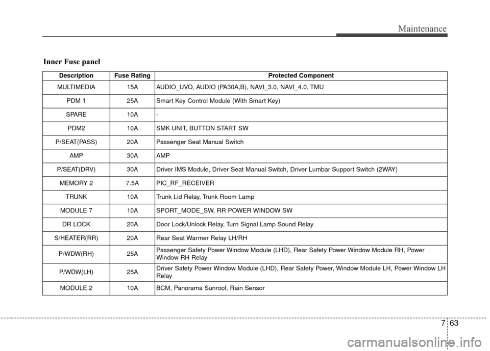
Inner Fuse panel
Description Fuse RatingProtected Component
MULTIMEDIA 15A AUDIO_UVO, AUDIO (PA30A,B), NAVI_3.0, NAVI_4.0, TMU
PDM 1 25A Smart Key Control Module (With Smart Key)
SPARE 10A -
PDM2 10A SMK UNIT, BUTTON START SW
P/SEAT(PASS) 20A Passenger Seat Manual Switch AMP 30A AMP
P/SEAT(DRV) 30A Driver IMS Module, Driver Seat Manual Switch, Driver Lumbar Support Switch (2WAY) MEMORY 2 7.5A PIC_RF_RECEIVER
TRUNK 10A Trunk Lid Relay, Trunk Room Lamp
MODULE 7 10A SPORT_MODE_SW, RR POWER WINDOW SW
DR LOCK 20A Door Lock/Unlock Relay, Turn Signal Lamp Sound Relay
S/HEATER(RR) 20A Rear Seat Warmer Relay LH/RH
P/WDW(RH) 25APassenger Safety Power Window Module (LHD), Rear Safety Power Window Module RH, Power
Window RH Relay
P/WDW(LH) 25ADriver Safety Power Window Module (LHD), Rear Safety Power, Window Module LH, Power Window LH
Relay
MODULE 2 10A BCM, Panorama Sunroof, Rain Sensor
Page 428 of 474
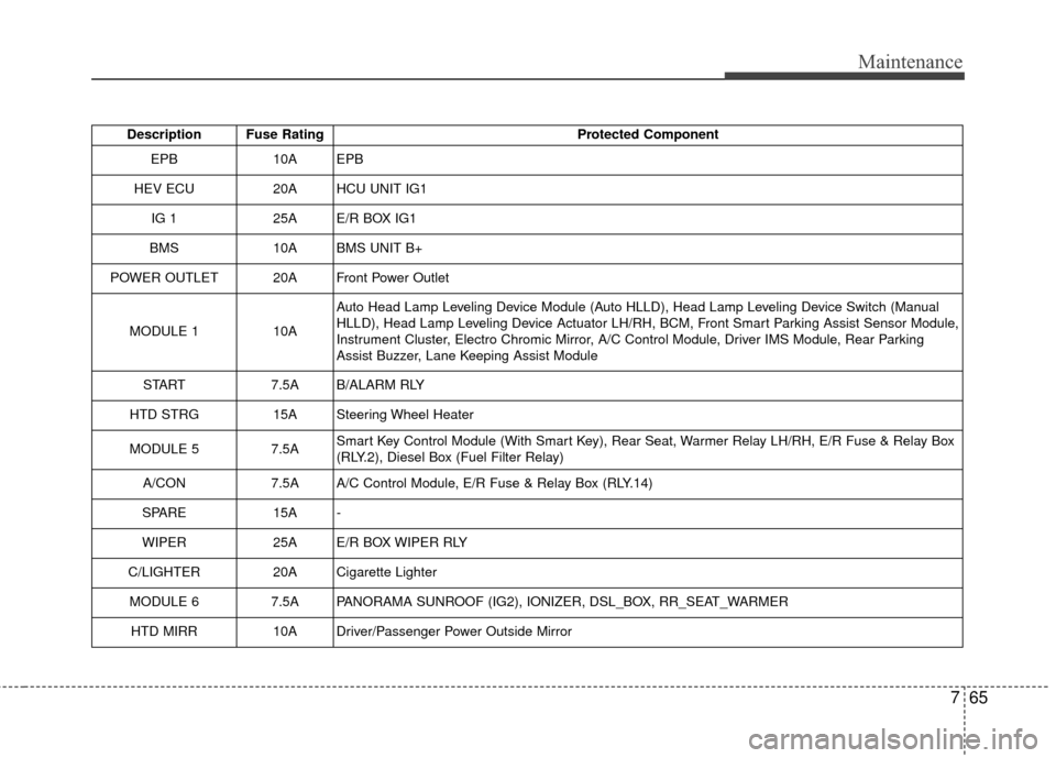
765
Maintenance
Description Fuse RatingProtected Component
EPB10AEPB
HEV ECU20AHCU UNIT IG1
IG 125AE/R BOX IG1
BMS 10A BMS UNIT B+
POWER OUTLET 20A Front Power Outlet
MODULE 1 10AAuto Head Lamp Leveling Device Module (Auto HLLD), Head Lamp Leveling Device Switch (Manual
HLLD), Head Lamp Leveling Device Actuator LH/RH, BCM, Front Smart Parking Assist Sensor Module,
Instrument Cluster, Electro Chromic Mirror, A/C Control Module, Driver IMS Module, Rear Parking
Assist Buzzer, Lane Keeping Assist Module
START 7.5A B/ALARM RLY
HTD STRG 15A Steering Wheel Heater
MODULE 5 7.5ASmart Key Control Module (With Smart Key), Rear Seat, Warmer Relay LH/RH, E/R Fuse & Relay Box
(RLY.2), Diesel Box (Fuel Filter Relay)
A/CON 7.5A A/C Control Module, E/R Fuse & Relay Box (RLY.14)
SPARE 15A -
WIPER 25A E/R BOX WIPER RLY
C/LIGHTER 20A Cigarette Lighter
MODULE 6 7.5A PANORAMA SUNROOF (IG2), IONIZER, DSL_BOX, RR_SEAT_WARMER
HTD MIRR 10A Driver/Passenger Power Outside Mirror
Page 430 of 474
767
Maintenance
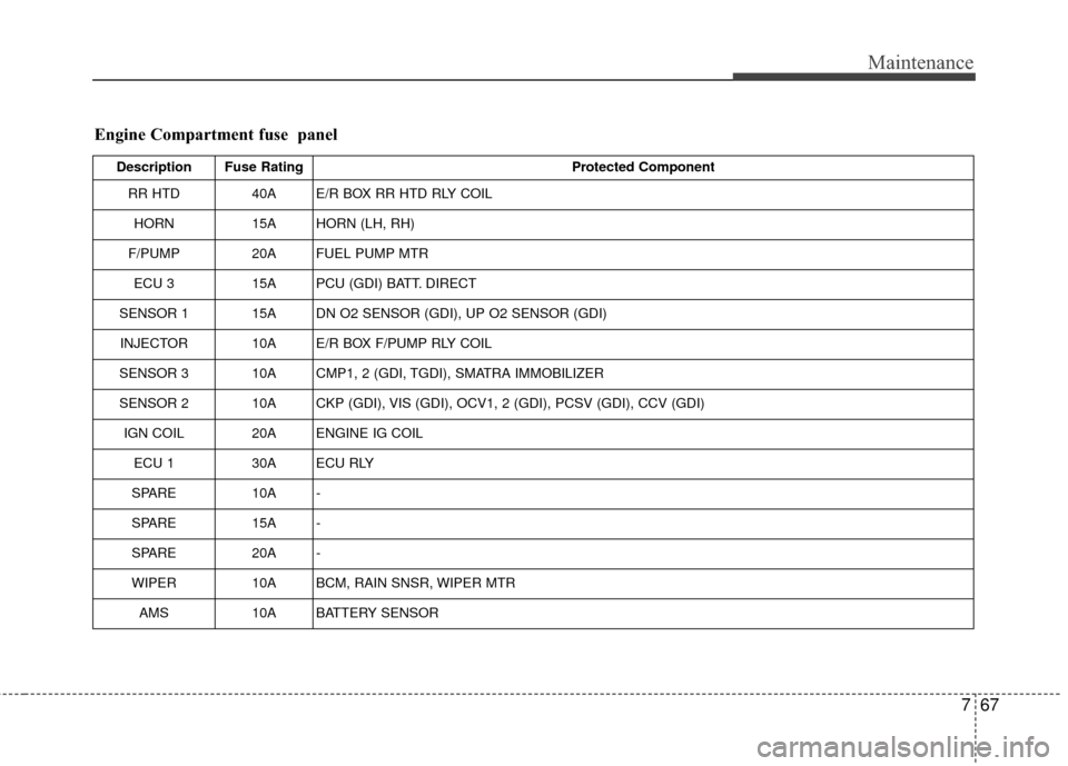
Engine Compartment fuse panel
Description Fuse RatingProtected Component
RR HTD 40A E/R BOX RR HTD RLY COIL
HORN 15A HORN (LH, RH)
F/PUMP 20A FUEL PUMP MTR
ECU 3 15A PCU (GDI) BATT. DIRECT
SENSOR 1 15A DN O2 SENSOR (GDI), UP O2 SENSOR (GDI) INJECTOR 10A E/R BOX F/PUMP RLY COIL
SENSOR 3 10A CMP1, 2 (GDI, TGDI), SMATRA IMMOBILIZER
SENSOR 2 10A CKP (GDI), VIS (GDI), OCV1, 2 (GDI), PCSV (GDI), CCV (GDI) IGN COIL 20A ENGINE IG COIL ECU 1 30A ECU RLY
SPARE 10A -
SPARE 15A -
SPARE 20A -
WIPER 10A BCM, RAIN SNSR, WIPER MTR
AMS 10A BATTERY SENSOR