KIA Rio 2005 2.G Owner's Manual
Manufacturer: KIA, Model Year: 2005, Model line: Rio, Model: KIA Rio 2005 2.GPages: 238, PDF Size: 2.6 MB
Page 151 of 238
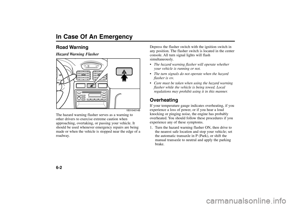
Road WarningHazard Warning FlasherThe hazard warning flasher serves as a warning to
other drivers to exercise extreme caution when
approaching, overtaking, or passing your vehicle. It
should be used whenever emergency repairs are being
made or when the vehicle is stopped near the edge of a
roadway.
Depress the flasher switch with the ignition switch in
any position. The flasher switch is located in the center
console. All turn signal lights will flash
simultaneously.
•The hazard warning flasher will operate whether
your vehicle is running or not.
The turn signals do not operate when the hazard
flasher is
ON
.
Care must be taken when using the hazard warning
flasher while the vehicle is being towed. Local
regulations may prohibit using it in this manner.
OverheatingIf your temperature gauge indicates overheating, if you
experience a loss of power, or if you hear a loud
knocking or pinging noise, the engine has probably
overheated. You should follow these procedures if you
experience any of these symptoms.
1. Turn the hazard warning flasher ON, then drive to
the nearest safe location and stop your vehicle; set
the automatic transaxle in P (Park), or shift the
manual transaxle to neutral and apply the parking
brake.
In Case Of An Emergency6-2
1B3104014B
RIO ENG CNA 6.qxd 7/29/05 5:15 PM Page 2
Page 152 of 238
2. Make sure the air conditioner is off.
3. If coolant or steam is boiling out of the radiator,
stop the engine, then turn the ignition switch to the
ON position. Do not restart the engine. The radiator
cooling fan will automatically operate with the
ignition switch in the ON position. If the cooling
fan does not operate, call an Authorized Kia Dealer
for assistance.
If coolant is not boiling out, allow the engine to
idle and open the hood to permit the engine to cool
gradually.
If the temperature does not go down with the
engine idling, stop the engine and allow sufficient
time for it to cool.4. The coolant level should then be checked. If the
level in the reservoir is low, look for leaks at the
radiator hoses and connections, heater hoses and
connections, radiator, and water pump. If you find a
major leak or another problem that may have
caused the engine to overheat, do not operate the
engine until the problem has been corrected. Call
an Authorized Kia Dealer for assistance.
If you do not find a leak or other problem, carefully
add coolant to the reservoir.
If the engine frequently overheats, have the cooling
system checked and repaired.
6-3
WARNING - Removing
Radiator Cap
Do not remove the radiator cap when the
engine and radiator are hot. Scalding hot
coolant and steam may blow out under
pressure. This could cause serious injury.
RIO ENG CNA 6.qxd 7/29/05 5:15 PM Page 3
Page 153 of 238
Emergency StartingJump StartingJump starting can be dangerous if done incorrectly.
Therefore, to avoid harm to yourself or damage to your
vehicle or battery, follow the jump starting procedures
on the next page. If in doubt, we strongly recommend
that you have a competent technician or towing service
jump start your vehicle.
Jump Starting Procedure
1. Make sure the booster battery is 12 volts and that
its negative terminal is grounded.
2. Check the electrolyte level of each of the battery
cells.
3. If the booster battery is in another vehicle, do not
allow the vehicles to touch.In Case Of An Emergency6-4
✽
NOTICE
Use only a 12volt jumper system. You can damage
a 12volt starting motor, ignition system, and other
electrical parts by using a 24-volt power supply
(two 12-volt batteries in series or a 24-volt motor
generator set).
WARNING - Battery
• Keep all flames or sparks away from the
battery. The battery produces hydrogen gas
which may explode if exposed to flame or
sparks.
Do not attempt to jump start vehicle if the
discharged battery is frozen or if the
electrolyte level is low; the battery may
rupture or explode.
RIO ENG CNA 6.qxd 7/29/05 5:15 PM Page 4
Page 154 of 238

6-5
Connection Jumper Cables
2 ( )
1 ( )
3 ( )
4
Connect cables in numerical order
and disconnect in reverse order.
Jumper
cablesBooster
battery
Discharged
battery
2FDA601
RIO ENG CNA 6.qxd 7/29/05 5:15 PM Page 5
Page 155 of 238
4. Turn off all unnecessary electrical loads.
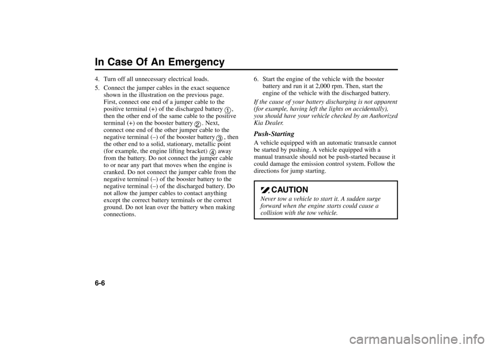
5. Connect the jumper cables in the exact sequence
shown in the illustration on the previous page.
First, connect one end of a jumper cable to the
positive terminal (+) of the discharged battery ,
then the other end of the same cable to the positive
terminal (+) on the booster battery . Next,
connect one end of the other jumper cable to the
negative terminal (–) of the booster battery , then
the other end to a solid, stationary, metallic point
(for example, the engine lifting bracket) away
from the battery. Do not connect the jumper cable
to or near any part that moves when the engine is
cranked. Do not connect the jumper cable from the
negative terminal (–) of the booster battery to the
negative terminal (–) of the discharged battery. Do
not allow the jumper cables to contact anything
except the correct battery terminals or the correct
ground. Do not lean over the battery when making
connections.6. Start the engine of the vehicle with the booster
battery and run it at 2,000 rpm. Then, start the
engine of the vehicle with the discharged battery.
If the cause of your battery discharging is not apparent
(for example, having left the lights on accidentally),
you should have your vehicle checked by an Authorized
Kia Dealer.
Push-StartingA vehicle equipped with an automatic transaxle cannot
be started by pushing. A vehicle equipped with a
manual transaxle should not be push-started because it
could damage the emission control system. Follow the
directions for jump starting.
In Case Of An Emergency6-6
CAUTION
Never tow a vehicle to start it. A sudden surge
forward when the engine starts could cause a
collision with the tow vehicle.
1
2
3
4
RIO ENG CNA 6.qxd 7/29/05 5:15 PM Page 6
Page 156 of 238
Electrical Circuit ProtectionFusesA vehicle’s electrical system is protected from
electrical overload damage by fuses.
This vehicle has two fuse panels, one located in the
driver’s side kick panel, the other in the engine
compartment near the battery. A fuse panel chart is
provided later in this section.
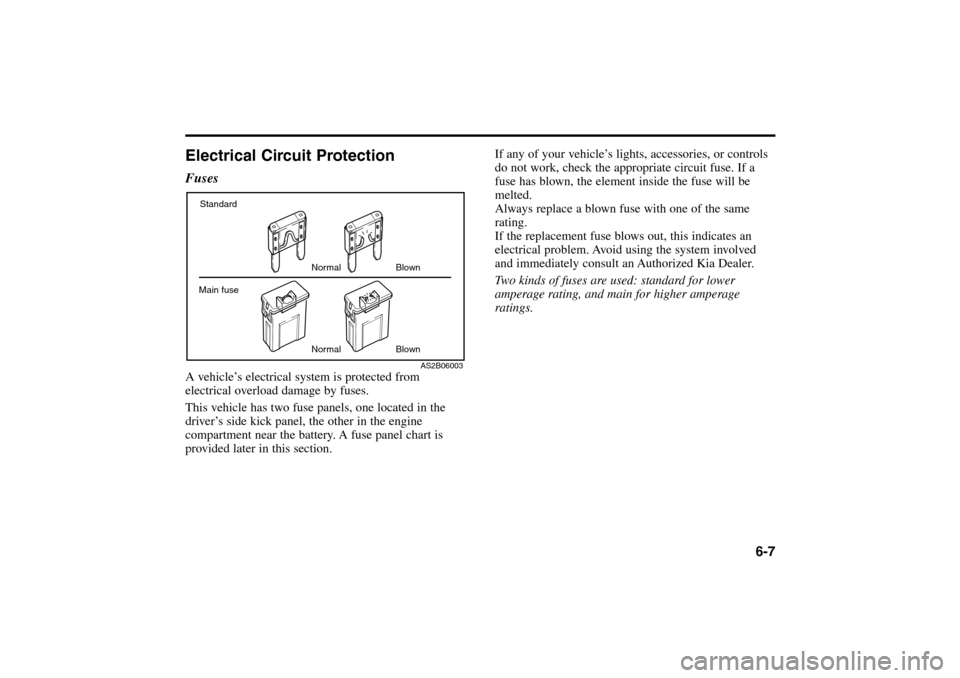
If any of your vehicle’s lights, accessories, or controls
do not work, check the appropriate circuit fuse. If a
fuse has blown, the element inside the fuse will be
melted.
Always replace a blown fuse with one of the same
rating.
If the replacement fuse blows out, this indicates an
electrical problem. Avoid using the system involved
and immediately consult an Authorized Kia Dealer.
Two kinds of fuses are used: standard for lower
amperage rating, and main for higher amperage
ratings.
6-7
Standard
Normal
NormalBlown
Blown Main fuse
AS2B06003
RIO ENG CNA 6.qxd 7/29/05 5:15 PM Page 7
Page 157 of 238
Fuse Replacement
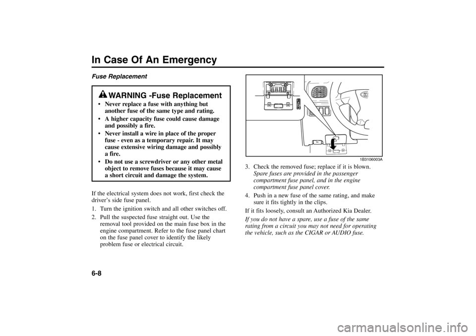
If the electrical system does not work, first check the
driver’s side fuse panel.
1. Turn the ignition switch and all other switches off.
2. Pull the suspected fuse straight out. Use the
removal tool provided on the main fuse box in the
engine compartment. Refer to the fuse panel chart
on the fuse panel cover to identify the likely
problem fuse or electrical circuit.3. Check the removed fuse; replace if it is blown.
Spare fuses are provided in the passenger
compartment fuse panel, and in the engine
compartment fuse panel cover.
4. Push in a new fuse of the same rating, and make
sure it fits tightly in the clips.
If it fits loosely, consult an Authorized Kia Dealer.
If you do not have a spare, use a fuse of the same
rating from a circuit you may not need for operating
the vehicle, such as the CIGAR or AUDIO fuse.In Case Of An Emergency6-8
WARNING -Fuse Replacement
Never replace a fuse with anything but
another fuse of the same type and rating.
A higher capacity fuse could cause damage
and possibly a fire.
Never install a wire in place of the proper
fuse - even as a temporary repair. It may
cause extensive wiring damage and possibly
a fire.
Do not use a screwdriver or any other metal
object to remove fuses because it may cause
a short circuit and damage the system.
1B3106003A
RIO ENG CNA 6.qxd 7/29/05 5:15 PM Page 8
Page 158 of 238
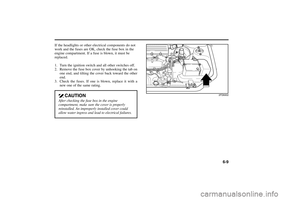
If the headlights or other electrical components do not
work and the fuses are OK, check the fuse box in the
engine compartment. If a fuse is blown, it must be
replaced.
1. Turn the ignition switch and all other switches off.
2. Remove the fuse box cover by unhooking the tab on
one end, and tilting the cover back toward the other
end.
3. Check the fuses. If one is blown, replace it with a
new one of the same rating.
6-9
CAUTION
After checking the fuse box in the engine
compartment, make sure the cover is properly
reinstalled. An improperly installed cover could
allow water ingress and lead to electrical failures.
2FDA602
RIO ENG CNA 6.qxd 7/29/05 5:15 PM Page 9
Page 159 of 238
In Case Of An Emergency6-10Fuse Panel DescriptionDriver’s side kick panel
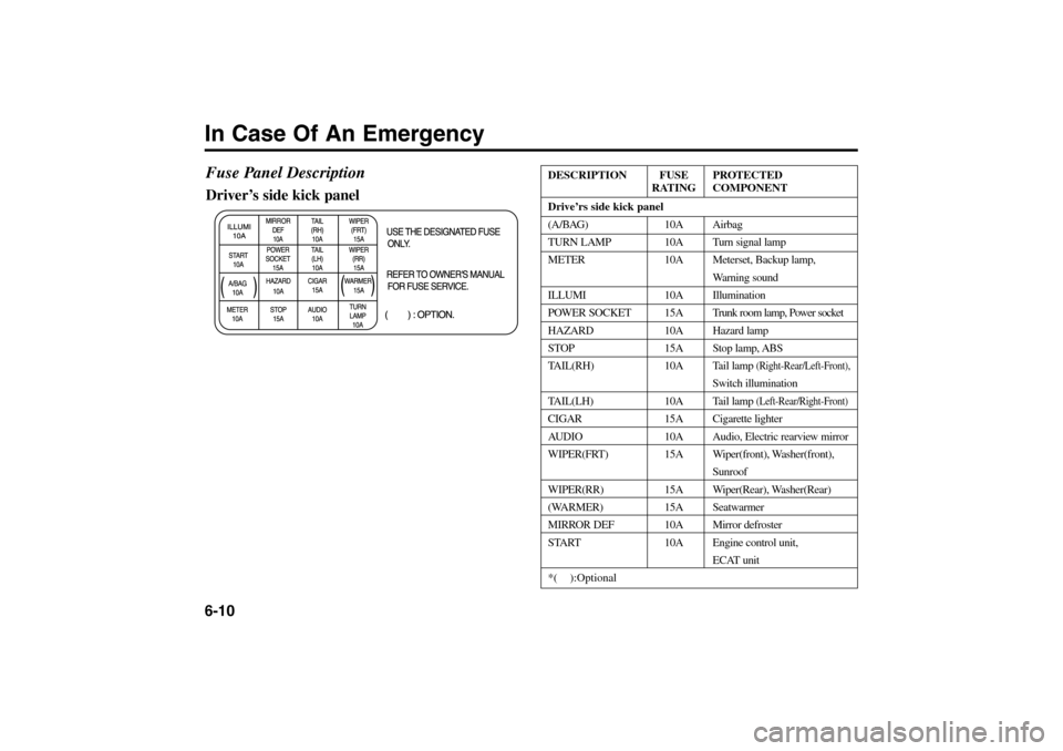
DESCRIPTION FUSE PROTECTED
RATING COMPONENT
Drive’rs side kick panel
(A/BAG) 10A Airbag
TURN LAMP 10A Turn signal lamp
METER 10A Meterset, Backup lamp,
Warning sound
ILLUMI 10A Illumination
POWER SOCKET 15A Trunk room lamp, Power socket
HAZARD 10A Hazard lamp
STOP 15A Stop lamp, ABS
TAIL(RH) 10A Tail lamp
(Right-Rear/Left-Front),
Switch illumination
TAIL(LH) 10A Tail lamp
(Left-Rear/Right-Front)
CIGAR 15A Cigarette lighter
AUDIO 10A Audio, Electric rearview mirror
WIPER(FRT) 15A Wiper(front), Washer(front),
Sunroof
WIPER(RR) 15A Wiper(Rear), Washer(Rear)
(WARMER) 15A Seatwarmer
MIRROR DEF 10A Mirror defroster
START 10A Engine control unit,
ECAT unit
*( ):Optional
RIO ENG CNA 6.qxd 7/29/05 5:15 PM Page 10
Page 160 of 238
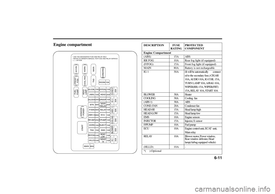
6-11
Engine compartment
DESCRIPTION FUSE PROTECTED
RATING COMPONENT
Engine Compartment
(ABS) 15A ABS
RR FOG 10A Rear fog light (if equipped)
(F/FOG) 15A Front fog light (if equipped)
MAIN 80A Battery is not rechargeable
IG 1 30A (It will be automatically connect
ed to the secondary fuse.) CIGAR
10A, AUDIO 10A, IG COIL 15A,
TURN LAMP 10A, A/BAG 10A,
WIPER(RR) 15A, WIPER(FRT)
15A, RELAY 10A, START 10A
BLOWER 30A Heater
COOLING 30A Cooling fan
(ABS 1) 30A ABS
COND. FAN 20A Condenser fan
HEAD-HI 15A Head lamp high
HEAD-LOW 15A Head lamp low
EMS 10A Engine sensors
INJECTOR 15A Injector, 0
2sensor
F/PUMP 10A Fuel pump
ECU 10A Engine control unit, ECAT unit,
Main relay
RELAY 10A Blower motor, Power window,
Rear window defroster, Head
lamp(Airbag equipped vehicle)
(HLLD) 10A
-
*( ):Optional
STARTWINDOW
POWERFUEL
PUMPFRONT
FOGA/CON
HEAD
LAMPCOOL.FANHORN
TNS MAIN
IG 1 BLOWER
COOL ING(ABS 1) IG 2 COND.F
( )( ) ( )
( )
( )
COND.FAN
ROOM 15A
IG COIL
(ABS)
D/LOCK
BTN
P/WIN
(ABS 2)
RR DEF
HORN
TNS
RR FOG
(HLLD)(F/FOG)
HEAD
S/ROOF
MAIN
RELAY
RELAY
ECU
F/PUMP
INJECT
EMS
HEAD
LOW
HEAD
HI 15A
15A
25A
30A
30A
30A
25A
10A
15A
10A
10A
80A15A
25A
15A
25A
10A
10A
10A
15A
10A
15A
15A
MAIN
30A 30A 30A 30A 30A 20A
* USE THE DESIGNATED FUSE AND RELAY ONLY.
* REFER TO OWNER'S MANUAL FOR FUSE AND RELAY SERVICE.
* ( ) : OPTION
RIO ENG CNA 6.qxd 7/29/05 5:15 PM Page 11