KIA VENGA 2015 Owners Manual
Manufacturer: KIA, Model Year: 2015, Model line: VENGA, Model: KIA VENGA 2015Pages: 480, PDF Size: 23.15 MB
Page 431 of 480
Maintenance
52
7
FUSES
A vehicle’s electrical system is protected
from electrical overload damage by
fuses. This vehicle has 2 (or 3) fuse panels, one
located in the driver’s side panel bolster,
the other in the engine compartment
near the battery.
If any of your vehicle’s lights, acces-
sories, or controls do not work, check the
appropriate circuit fuse. If the fuse is dis-
connected, every electrical system pro-
tected by the fuse will not operate.
Therefore, you must change the fuse. If
the electrical system does not work, first
check the driver’s side fuse panel.
Always replace a blown fuse with one of
the same rating.
Before replacing a blown fuse, disconnect
the negative battery cable.
If the replacement fuse blows, this indi-
cates an electrical problem. Avoid using
the system involved and we recommend
that you consult an authorised Kia deal-
er.
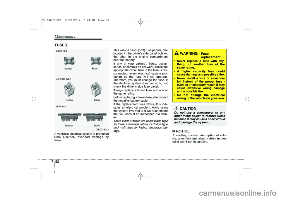
Three kinds of fuses are used: blade type
for lower amperage rating, cartridge typeand multi fuse for higher amperage rat-
ings.
✽✽ NOTICE
According to electronics option of vehi-
cle, some fuse and relays written in bom
label could not be applied.OBK079042
Normal
Normal
Cartridge type Multi fuse Blown
Blown
Normal Blown
CAUTION
Do not use a screwdriver or any other metal object to remove fusesbecause it may cause a short circuit and damage the system.
Blade typeWARNING - Fuse
replacement
Never replace a fuse with any- thing but another fuse of the same rating.
A higher capacity fuse could cause damage and possibly a fire.
Never install a wire or aluminum foil instead of the proper fuse -
even as a temporary repair. It may
cause extensive wiring damage
and a possible fire.
Do not change the electrical
wiring of the vehicle on your own.
YN RHD 7.QXP 11/20/2014 6:44 PM Page 52
Page 432 of 480
753
Maintenance
✽✽NOTICE
The actual fuse/relay panel label may
differ from equipped items.
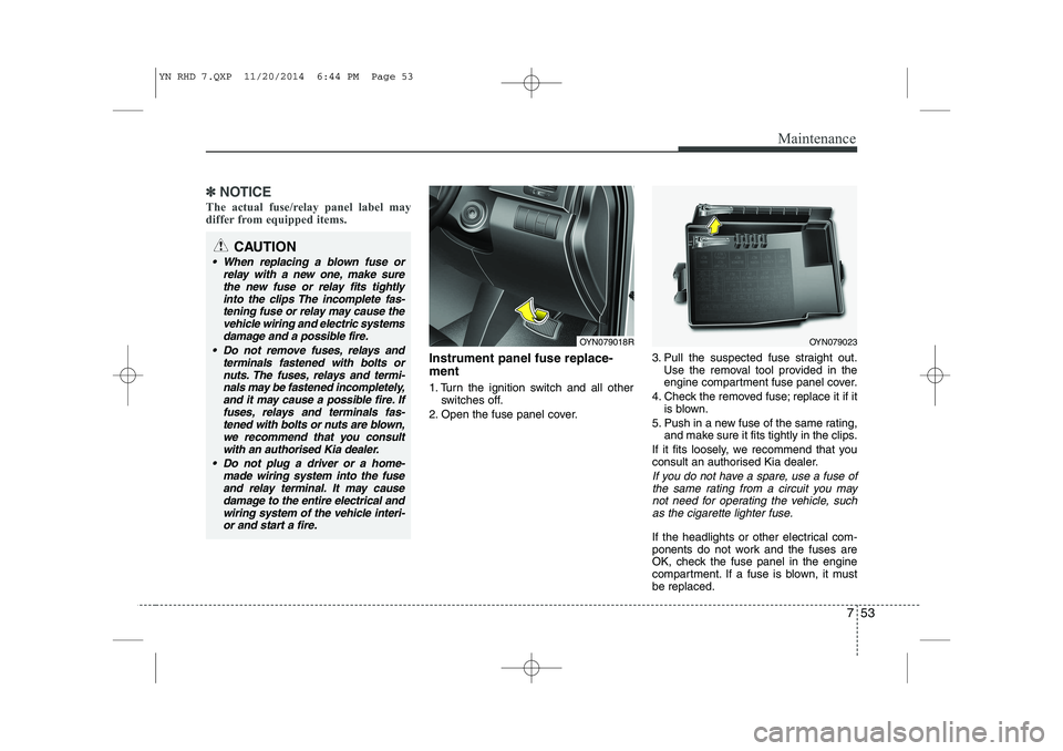
Instrument panel fuse replace- ment
1. Turn the ignition switch and all other switches off.
2. Open the fuse panel cover. 3. Pull the suspected fuse straight out.
Use the removal tool provided in the
engine compartment fuse panel cover.
4. Check the removed fuse; replace it if it is blown.
5. Push in a new fuse of the same rating, and make sure it fits tightly in the clips.
If it fits loosely, we recommend that you
consult an authorised Kia dealer.
If you do not have a spare, use a fuse of the same rating from a circuit you may
not need for operating the vehicle, suchas the cigarette lighter fuse.
If the headlights or other electrical com-
ponents do not work and the fuses are
OK, check the fuse panel in the engine
compartment. If a fuse is blown, it mustbe replaced.
OYN079023OYN079018R
CAUTION
When replacing a blown fuse or
relay with a new one, make surethe new fuse or relay fits tightly into the clips The incomplete fas-tening fuse or relay may cause the
vehicle wiring and electric systems damage and a possible fire.
Do not remove fuses, relays and terminals fastened with bolts or
nuts. The fuses, relays and termi-nals may be fastened incompletely, and it may cause a possible fire. Iffuses, relays and terminals fas-
tened with bolts or nuts are blown, we recommend that you consultwith an authorised Kia dealer.
Do not plug a driver or a home- made wiring system into the fuse
and relay terminal. It may cause damage to the entire electrical andwiring system of the vehicle interi-or and start a fire.
YN RHD 7.QXP 11/20/2014 6:44 PM Page 53
Page 433 of 480
Maintenance
54
7
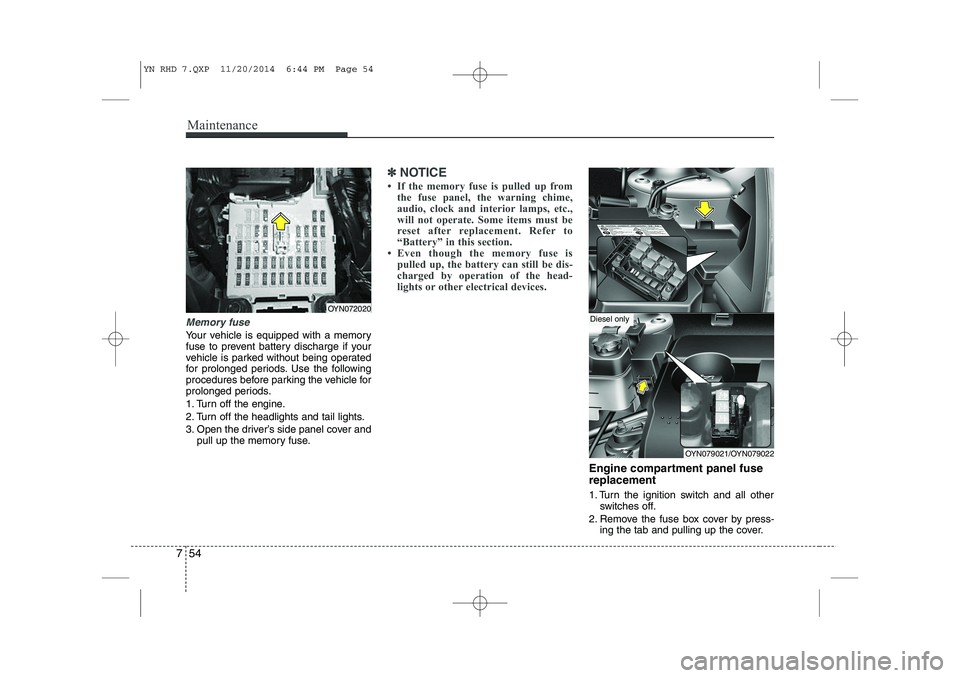
Memory fuse
Your vehicle is equipped with a memory
fuse to prevent battery discharge if your
vehicle is parked without being operated
for prolonged periods. Use the following
procedures before parking the vehicle for
prolonged periods.
1. Turn off the engine.
2. Turn off the headlights and tail lights.
3. Open the driver’s side panel cover and
pull up the memory fuse.
✽✽ NOTICE
If the memory fuse is pulled up from the fuse panel, the warning chime,
audio, clock and interior lamps, etc.,
will not operate. Some items must be
reset after replacement. Refer to
“Battery” in this section.
Even though the memory fuse is
pulled up, the battery can still be dis-
charged by operation of the head-
lights or other electrical devices.
Engine compartment panel fuse replacement
1. Turn the ignition switch and all other switches off.
2. Remove the fuse box cover by press- ing the tab and pulling up the cover.
OYN072020
OYN079021/OYN079022
Diesel only
YN RHD 7.QXP 11/20/2014 6:44 PM Page 54
Page 434 of 480
755
Maintenance
3. Check the removed fuse; replace it if itis blown. To remove or insert the fuse, use the fuse puller in the engine com-
partment fuse panel.
4. Push in a new fuse of the same rating, and make sure it fits tightly in the clips.
If it fits loosely, we recommend that
you consult an authorised Kia dealer.
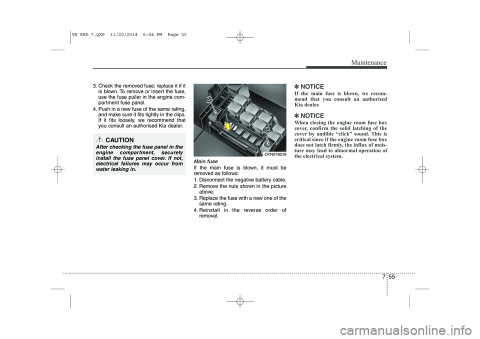
Main fuse
If the main fuse is blown, it must be
removed as follows:
1. Disconnect the negative battery cable.
2. Remove the nuts shown in the pictureabove.
3. Replace the fuse with a new one of the same rating.
4. Reinstall in the reverse order of removal.
✽✽ NOTICE
If the main fuse is blown, we recom-
mend that you consult an authorised
Kia dealer.
✽
✽ NOTICE
When closing the engine room fuse box
cover, confirm the solid latching of the
cover by audible “click” sound. This is
critical since if the engine room fuse box
does not latch firmly, the influx of mois-
ture may lead to abnormal operation of
the electrical system.
CAUTION
After checking the fuse panel in the engine compartment, securely
install the fuse panel cover. If not,electrical failures may occur fromwater leaking in.
OYN079019
YN RHD 7.QXP 11/20/2014 6:44 PM Page 55
Page 435 of 480
Maintenance
56
7
✽✽
NOTICE
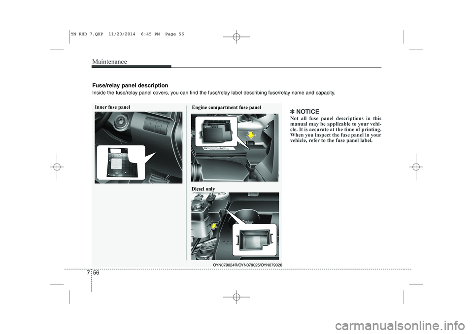
Not all fuse panel descriptions in this
manual may be applicable to your vehi-
cle. It is accurate at the time of printing.
When you inspect the fuse panel in your
vehicle, refer to the fuse panel label.Inner fuse panel Engine compartment fuse panel
OYN079024R/OYN079025/OYN079026
Diesel only
Fuse/relay panel description
Inside the fuse/relay panel covers, you can find the fuse/relay label describing fuse/relay name and capacity.
YN RHD 7.QXP 11/20/2014 6:45 PM Page 56
Page 436 of 480
757
Maintenance
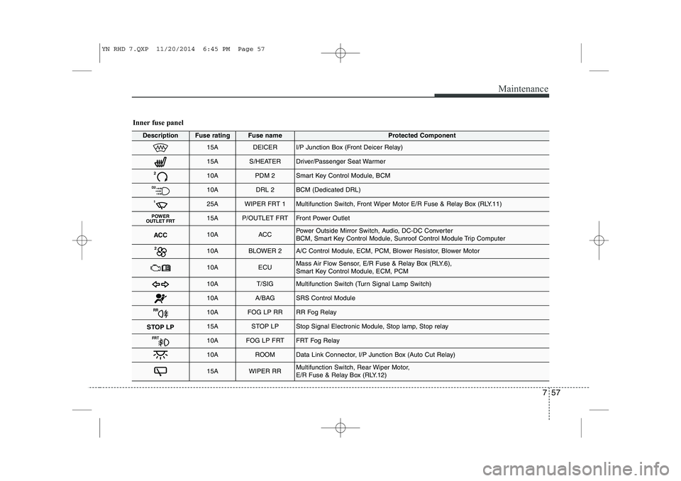
Inner fuse panel
DescriptionFuse ratingFuse nameProtected Component
15ADEICERI/P Junction Box (Front Deicer Relay)
15AS/HEATERDriver/Passenger Seat Warmer
210APDM 2Smart Key Control Module, BCM
D210ADRL 2BCM (Dedicated DRL)
125AWIPER FRT 1Multifunction Switch, Front Wiper Motor E/R Fuse & Relay Box (RLY.11)
POWER
OUTLET FRT15AP/OUTLET FRTFront Power Outlet
ACC10AACCPower Outside Mirror Switch, Audio, DC-DC Converter
BCM, Smart Key Control Module, Sunroof Control Module Trip Computer
210ABLOWER 2A/C Control Module, ECM, PCM, Blower Resistor, Blower Motor
10AECUMass Air Flow Sensor, E/R Fuse & Relay Box (RLY.6),
Smart Key Control Module, ECM, PCM
10AT/SIGMultifunction Switch (Turn Signal Lamp Switch)
10AA/BAGSRS Control Module
RR10AFOG LP RRRR Fog Relay
STOP LP15ASTOP LPStop Signal Electronic Module, Stop lamp, Stop relay
FRT10AFOG LP FRTFRT Fog Relay
10AROOMData Link Connector, I/P Junction Box (Auto Cut Relay)
15AWIPER RRMultifunction Switch, Rear Wiper Motor,
E/R Fuse & Relay Box (RLY.12)
YN RHD 7.QXP 11/20/2014 6:45 PM Page 57
Page 437 of 480
Maintenance
58
7
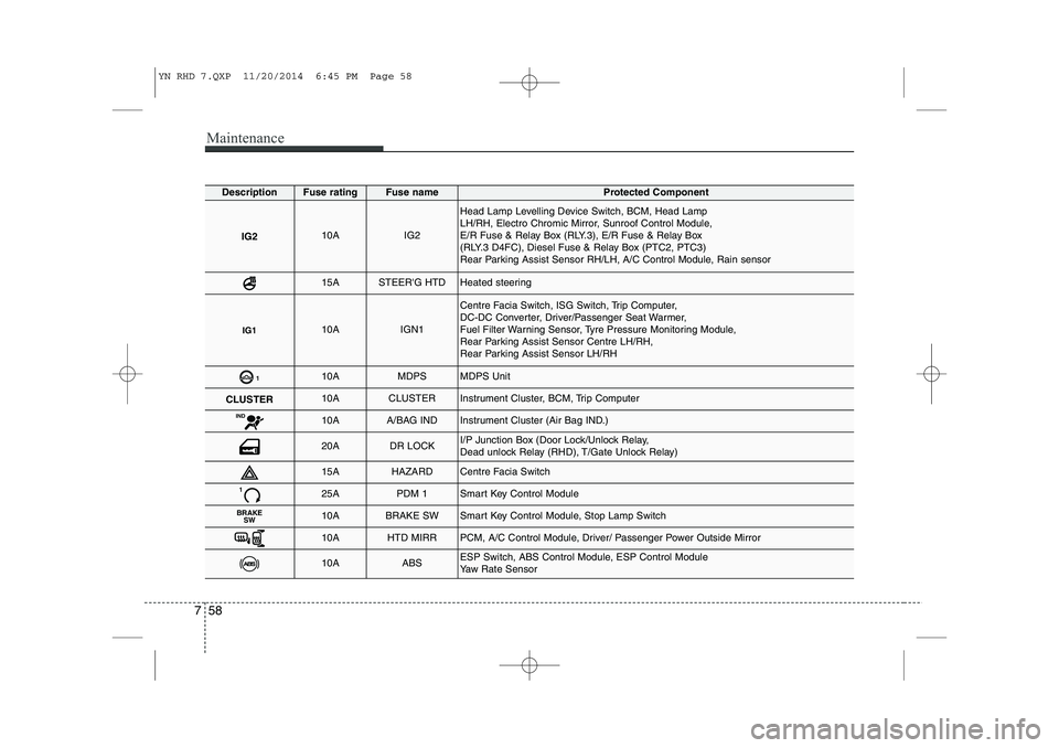
DescriptionFuse ratingFuse nameProtected Component
IG210AIG2
Head Lamp Levelling Device Switch, BCM, Head Lamp
LH/RH, Electro Chromic Mirror, Sunroof Control Module,
E/R Fuse & Relay Box (RLY.3), E/R Fuse & Relay Box
(RLY.3 D4FC), Diesel Fuse & Relay Box (PTC2, PTC3)
Rear Parking Assist Sensor RH/LH, A/C Control Module, Rain sensor
15ASTEER'G HTDHeated steering
IG110AIGN1
Centre Facia Switch, ISG Switch, Trip Computer,
DC-DC Converter, Driver/Passenger Seat Warmer,
Fuel Filter Warning Sensor, Tyre Pressure Monitoring Module,
Rear Parking Assist Sensor Centre LH/RH,
Rear Parking Assist Sensor LH/RH
110AMDPSMDPS Unit
CLUSTER10ACLUSTERInstrument Cluster, BCM, Trip Computer
IND10AA/BAG INDInstrument Cluster (Air Bag IND.)
20ADR LOCKI/P Junction Box (Door Lock/Unlock Relay,
Dead unlock Relay (RHD), T/Gate Unlock Relay)
15AHAZARDCentre Facia Switch
125APDM 1Smart Key Control Module
BRAKE
SW10ABRAKE SWSmart Key Control Module, Stop Lamp Switch
10AHTD MIRRPCM, A/C Control Module, Driver/ Passenger Power Outside Mirror
10AABSESP Switch, ABS Control Module, ESP Control Module
Yaw Rate Sensor
YN RHD 7.QXP 11/20/2014 6:45 PM Page 58
Page 438 of 480
759
Maintenance
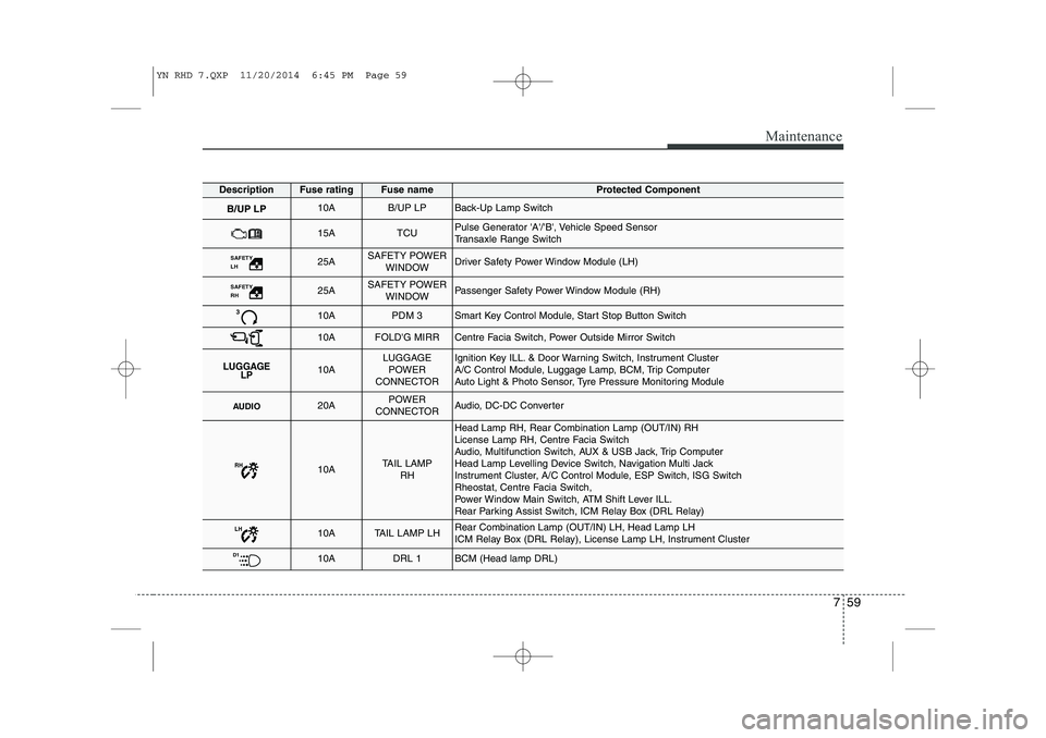
DescriptionFuse ratingFuse nameProtected Component
B/UP LP10AB/UP LPBack-Up Lamp Switch
15ATCUPulse Generator 'A'/'B', Vehicle Speed Sensor
Transaxle Range Switch
SAFETY LH 25ASAFETY POWERWINDOWDriver Safety Power Window Module (LH)
SAFETY RH 25ASAFETY POWERWINDOWPassenger Safety Power Window Module (RH)
310APDM 3Smart Key Control Module, Start Stop Button Switch
10AFOLD'G MIRRCentre Facia Switch, Power Outside Mirror Switch
LUGGAGE LP10ALUGGAGE
POWER
CONNECTORIgnition Key ILL. & Door Warning Switch, Instrument Cluster
A/C Control Module, Luggage Lamp, BCM, Trip Computer
Auto Light & Photo Sensor, Tyre Pressure Monitoring Module
AUDIO20APOWER
CONNECTORAudio, DC-DC Converter
RH10ATAIL LAMP RH
Head Lamp RH, Rear Combination Lamp (OUT/IN) RH
License Lamp RH, Centre Facia Switch
Audio, Multifunction Switch, AUX & USB Jack, Trip Computer
Head Lamp Levelling Device Switch, Navigation Multi Jack
Instrument Cluster, A/C Control Module, ESP Switch, ISG Switch
Rheostat, Centre Facia Switch,
Power Window Main Switch, ATM Shift Lever ILL.
Rear Parking Assist Switch, ICM Relay Box (DRL Relay)
LH10ATAIL LAMP LHRear Combination Lamp (OUT/IN) LH, Head Lamp LH
ICM Relay Box (DRL Relay), License Lamp LH, Instrument Cluster
D110ADRL 1BCM (Head lamp DRL)
YN RHD 7.QXP 11/20/2014 6:45 PM Page 59
Page 439 of 480
Maintenance
60
7
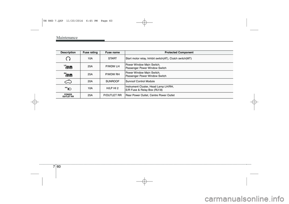
DescriptionFuse ratingFuse nameProtected Component
10ASTARTStart motor relay, Inhibit switch(AT), Clutch switch(MT)
LH25AP/WDW LHPower Window Main Switch,
Passenger Power Window Switch
RH25AP/WDW RHPower Window Main Switch,
Passenger Power Window Switch
20ASUNROOFSunroof Control Module
IND10AH/LP HI 2Instrument Cluster, Head Lamp LH/RH,
E/R Fuse & Relay Box (RLY.8)
POWER
OUTLET RR25AP/OUTLET RRRear Power Outlet, Centre Power Outlet
YN RHD 7.QXP 11/20/2014 6:45 PM Page 60
Page 440 of 480
761
Maintenance
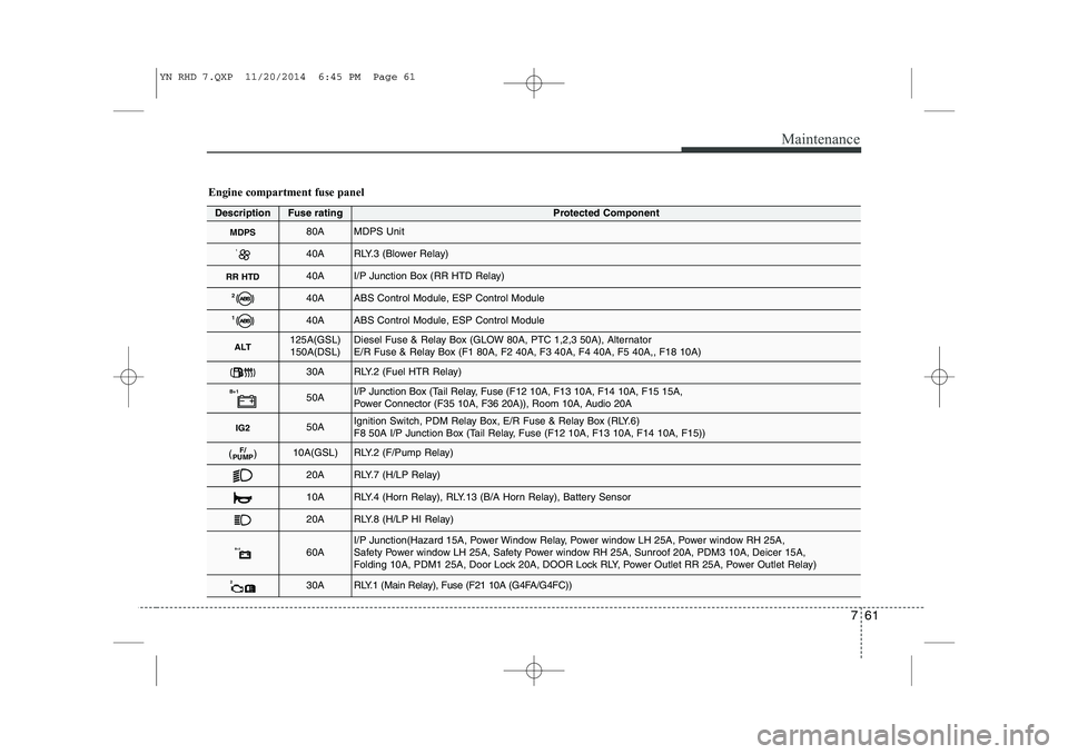
Engine compartment fuse panel
DescriptionFuse ratingProtected Component
MDPS80AMDPS Unit
140ARLY.3 (Blower Relay)
RR HTD40AI/P Junction Box (RR HTD Relay)
240AABS Control Module, ESP Control Module
140AABS Control Module, ESP Control Module
ALT125A(GSL)150A(DSL)Diesel Fuse & Relay Box (GLOW 80A, PTC 1,2,3 50A), Alternator
E/R Fuse & Relay Box (F1 80A, F2 40A, F3 40A, F4 40A, F5 40A,, F18 10A)
30ARLY.2 (Fuel HTR Relay)
B+150AI/P Junction Box (Tail Relay, Fuse (F12 10A, F13 10A, F14 10A, F15 15A,
Power Connector (F35 10A, F36 20A)), Room 10A, Audio 20A
IG250AIgnition Switch, PDM Relay Box, E/R Fuse & Relay Box (RLY.6)
F8 50A I/P Junction Box (Tail Relay, Fuse (F12 10A, F13 10A, F14 10A, F15))
F/
PUMP( )10A(GSL)RLY.2 (F/Pump Relay)
20ARLY.7 (H/LP Relay)
10ARLY.4 (Horn Relay), RLY.13 (B/A Horn Relay), Battery Sensor
20ARLY.8 (H/LP HI Relay)
B+260AI/P Junction(Hazard 15A, Power Window Relay, Power window LH 25A, Power window RH 25A,
Safety Power window LH 25A, Safety Power window RH 25A, Sunroof 20A, PDM3 10A, Deicer 15A,
Folding 10A, PDM1 25A, Door Lock 20A, DOOR Lock RLY, Power Outlet RR 25A, Power Outlet Relay)
230ARLY.1 (Main Relay), Fuse (F21 10A (G4FA/G4FC))
YN RHD 7.QXP 11/20/2014 6:45 PM Page 61