ESP Lancia Flavia 2012 Owner handbook (in English)
[x] Cancel search | Manufacturer: LANCIA, Model Year: 2012, Model line: Flavia, Model: Lancia Flavia 2012Pages: 233, PDF Size: 2.61 MB
Page 94 of 233
NOTE:
Once a heat setting is selected, heat
will be felt within two to five min-
utes.WARNING!
Persons who are unable to feelpain to the skin because of ad-
vanced age, chronic illness, diabe-
tes, spinal cord injury, medica-
tion, alcohol use, exhaustion or
other physical condition must ex-
ercise care when using the seat
heater. It may cause burns even at
low temperatures, especially if
used for long periods of time.
Do not place anything on the seat
that insulates against heat, such
as a blanket or cushion. This may
cause the seat heater to overheat.
Sitting in a seat that has been
overheated could cause serious
burns due to the increased surface
temperature of the seat. RECLINER ADJUSTMENT
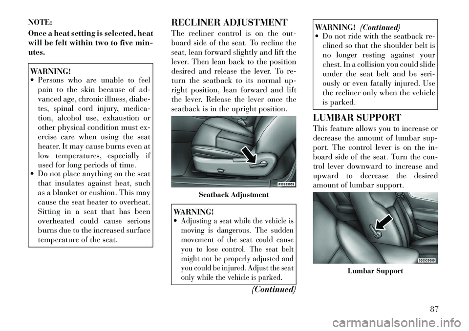
The recliner control is on the out-
board side of the seat. To recline the
seat, lean forward slightly and lift the
lever. Then lean back to the position
desired and release the lever. To re-
turn the seatback to its normal up-
right position, lean forward and lift
the lever. Release the lever once the
seatback is in the upright position.
WARNING!
Adjusting a seat while the vehicle is
moving is dangerous. The sudden
movement of the seat could cause
you to lose control. The seat belt
might not be properly adjusted and
you could be injured. Adjust the seat
only while the vehicle is parked.
(Continued)
WARNING!
(Continued)
Do not ride with the seatback re-
clined so that the shoulder belt is
no longer resting against your
chest. In a collision you could slide
under the seat belt and be seri-
ously or even fatally injured. Use
the recliner only when the vehicle
is parked.
LUMBAR SUPPORT
This feature allows you to increase or
decrease the amount of lumbar sup-
port. The control lever is on the in-
board side of the seat. Turn the con-
trol lever downward to increase and
upward to decrease the desired
amount of lumbar support.
Seatback Adjustment
Lumbar Support
87
Page 101 of 233
A courtesy light is also found in the
rear of the center console. You can
turn this light on and off from the
dimmer control in the multifunction
lever. This light is also controlled au-
tomatically by the Illuminated Entry
System.
Headlight Leveling System
This system allows the driver to main-
tain proper headlight beam position
with the road surface regardless of
vehicle load.
The headlight leveling switch is lo-
cated on the instrument panel below
the radio.To operate: push the head-
light leveling switch until
the appropriate number,
which corresponds to the
load listed on the following chart, il-
luminates on the switch.
0 Driver only, or driver and front passenger.
1 All seating positions
occupied.
2 All seating positions
occupied, plus an
evenly distributed load
in the luggage com-
partment. The total
weight of passengers
and load does not ex-
ceed the maximum
load capacity of the
vehicle.
3 Driver, plus an evenly
distributed load in the
luggage compartment.
The total weight of the
driver and load does
not exceed the maxi-
mum load capacity of
the vehicle.
Calculations based on a passenger
weight of 75 kg. BATTERY SAVER FEATURE
To protect the battery, the interior
lights will turn off automatically
10 minutes after the ignition switch is
moved to the LOCK position. This
will occur if the interior lights were
switched on manually or are on be-
cause a door is open.
WINDSHIELD WIPERS
AND WASHERS
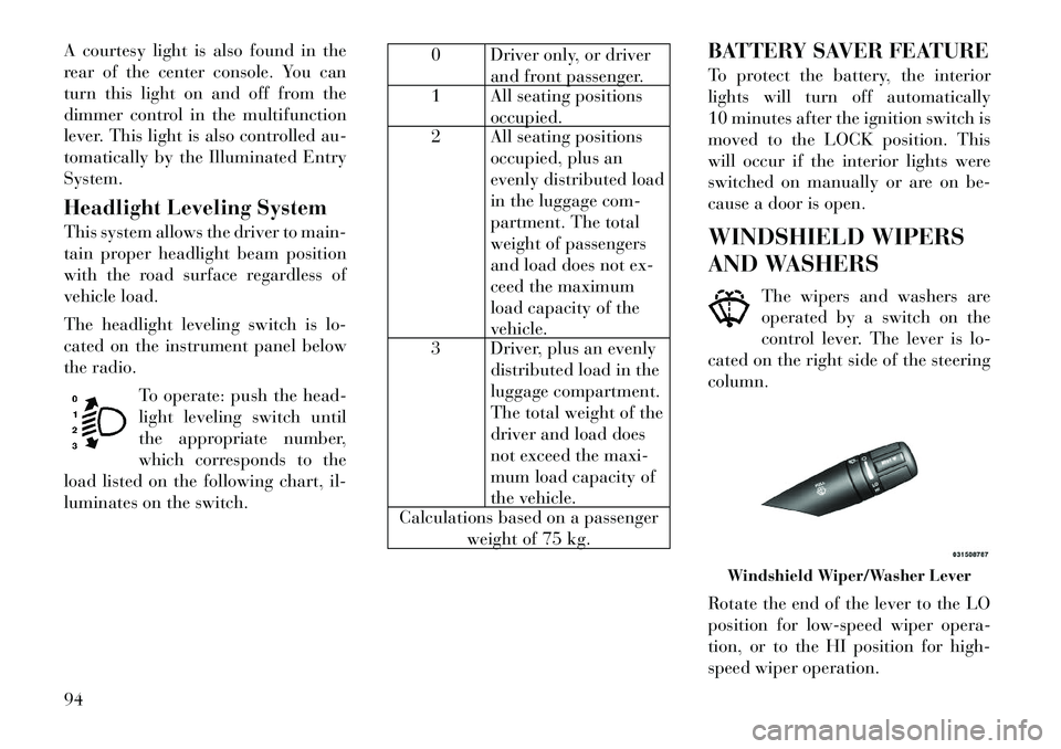
The wipers and washers are
operated by a switch on the
control lever. The lever is lo-
cated on the right side of the steering
column.
Rotate the end of the lever to the LO
position for low-speed wiper opera-
tion, or to the HI position for high-
speed wiper operation.
Windshield Wiper/Washer Lever
94
Page 120 of 233
bel. (If your vehicle has tires of a
different size than the size indicated
on the vehicle placard or tire inflation
pressure label, you should determine
the proper tire inflation pressure for
those tires.)
As an added safety feature, your ve-
hicle has been equipped with a Tire
Pressure Monitoring System (TPMS)
that illuminates a low tire pressure
telltale when one or more of your tires
is significantly under-inflated. Ac-
cordingly, when the low tire pressure
telltale illuminates, you should stop
and check your tires as soon as pos-
sible, and inflate them to the proper
pressure. Driving on a significantly
under-inflated tire causes the tire to
overheat and can lead to tire failure.
Under-inflation also reduces fuel effi-
ciency and tire tread life, and may
affect the vehicle’s handling and stop-
ping ability.Please note that the TPMS is not a
substitute for proper tire maintenance,
and it is the driver’s responsibility to
maintain correct tire pressure, even if
under-inflation has not reached thelevel to trigger illumination of the
TPMS low tire pressure telltale.
Your vehicle has also been equipped
with a TPMS malfunction indicator to
indicate when the system is not oper-
ating properly. The TPMS malfunc-
tion indicator is combined with the
low tire pressure telltale. When the
system detects a malfunction, the tell-
tale will flash for approximately one
minute and then remain continuously
illuminated. This sequence will con-
tinue upon subsequent vehicle start-
ups as long as the malfunction exists.
When the malfunction indicator is il-
luminated, the system may not be
able to detect or signal low tire pres-
sure as intended. TPMS malfunctions
may occur for a variety of reasons,
including the installation of replace-
ment or alternate tires or wheels on
the vehicle that prevent the TPMS
from functioning properly. Always
check the TPMS malfunction telltale
after replacing one or more tires or
wheels on your vehicle, to ensure that
the replacement or alternate tires and
wheels allow the TPMS to continue to
function properly.
CAUTION!
The TPMS has been optimized for
the original equipment tires and
wheels. TPMS pressures and warn-
ing have been established for the tire
size equipped on your vehicle. Un-
desirable system operation or sensor
damage may result when using re-
placement equipment that is not of
the same size, type, and/or style.
Aftermarket wheels can cause sensor
damage. Do not use tire sealant from
a can or balance beads if your ve-
hicle is equipped with a TPMS, as
damage to the sensors may result.
26. Malfunction Indicator Light
(MIL) The Malfunction Indicator
Light (MIL) is part of an on-
board diagnostic system
called OBD that monitors
emissions, engine, and automatic
transmission control systems. The
light will illuminate when the key is in
the ON/RUN position before engine
start. If the bulb does not come on
when turning the key from LOCK to
ON/RUN, have the condition checked
promptly.
113
Page 146 of 233

CAUTION!
Before moving the shift lever outof PARK, you must turn the igni-
tion switch from the LOCK/OFF
position to the ON/RUN position,
and also press the brake pedal.
Otherwise, damage to the shift le-
ver could result.
DO NOT race the engine when
shifting from PARK or NEUTRAL
into another gear range, as this
can damage the drivetrain.
The following indicators should be
used to ensure that you have engaged
the shift lever into the PARK position:
When shifting into PARK, move the shift lever all the way forward and
to the left until it stops and is fully
seated.
Look at the shift lever position dis- play and verify that it indicates the
PARK position.
With brake pedal released, verify that the shift lever will not move out
of PARK. REVERSE
This range is for moving the vehicle
backward. Shift into REVERSE only
after the vehicle has come to a com-
plete stop.
NEUTRAL
Use this range when vehicle is stand-
ing for prolonged periods with engine
running. The engine may be started in
this range. Set the parking brake and
shift the transmission into PARK if
you must leave the vehicle.
WARNING!
Do not coast in NEUTRAL and
never turn off the ignition to coast
down a hill. These are unsafe prac-
tices that limit your response to
changing traffic or road conditions.
You might lose control of the vehicle
and have a collision.
CAUTION!
Towing the vehicle, coasting, or
driving for any other reason with the
transmission in NEUTRAL can re-
sult in severe transmission damage.
Refer to “Recreational Towing” in
“Starting And Operating” and
“Towing A Disabled Vehicle” in
What To Do In Emergencies” for
further information.
DRIVE
This range should be used for most
city and highway driving. It provides
the smoothest upshifts and down-
shifts, and the best fuel economy. The
transmission automatically upshifts
through underdrive first, second,
third, and fourth gears, direct fifth
gear and overdrive sixth gear. The
DRIVE position provides optimum
driving characteristics under all nor-
mal operating conditions.
When frequent transmission shifting
occurs (such as when operating the
vehicle under heavy loading condi-
tions, in hilly terrain, traveling into
strong head winds, or while towing
heavy trailers), use the AutoStick®
139
Page 148 of 233

Torque Converter Clutch
A feature designed to improve fuel
economy has been included in the au-
tomatic transmission on your vehicle.
A clutch within the torque converter
engages automatically at calibrated
speeds. This may result in a slightly
different feeling or response during
normal operation in the upper gears.
When the vehicle speed drops or dur-
ing some accelerations, the clutch au-
tomatically disengages.
NOTE:
The torque converter clutch will
not engage until the transmission
fluid and engine coolant are warm
[usually after 2 to 5 km of driving].
Because the engine speed is higher
when the torque converter clutch
is not engaged, it may seem as if the
transmission is not shifting into
Overdrive when cold. This is nor-
mal. Using the AutoStick® feature,
when the transmission is suffi-
ciently warm, will demonstrate
that the transmission is able to
shift into and out of Overdrive.AUTOSTICK®
AutoStick® is a driver-interactive
feature providing manual shift con-
trol, giving you more control of the
vehicle. AutoStick® allows you to
maximize engine braking, eliminate
undesirable upshifts and downshifts,
and improve overall vehicle perfor-
mance. This system can also provide
you with more control during passing,
city driving, cold slippery conditions,
mountain driving, and many other
situations.
OPERATION
When the shift lever is in the
AutoStick® position (below the
DRIVE position), it can be moved
from side to side. This allows the
driver to manually select the trans-
mission gear being used. Moving the
shift lever to the left (-) triggers a
downshift and to the right (+) an up-
shift. The gear position will display in
the instrument cluster on the trans-
mission range indicator.
NOTE:
In AutoStick® mode, the transmis-
sion will only shift up or down
when the driver moves the shift
lever to the right (+) or left (-), or as
described below.
AutoStick® is deactivated when the
shift lever is moved from the
AutoStick (+/-) position into the
DRIVE position.
GENERAL INFORMATION
You can start out, from a stop, in
any gear except sixth. The system
will ignore attempts to upshift at
too low of a vehicle speed.
If a ratio other than first gear is selected, and the vehicle is brought
to a stop, the transmission control
logic will automatically select the
first gear ratio.
Starting out in second gear is help- ful in snowy or icy conditions. To
select second gear after the vehicle
is brought to a stop, tap the shift
lever to the right (+) once.
Avoid using speed control when AutoStick® is engaged.
141
Page 151 of 233

POWER STEERING
The standard power steering system
will give you good vehicle response
and increased ease of maneuverability
in tight spaces. The system will pro-
vide mechanical steering capability if
power assist is lost.
If for some reason the power assist is
interrupted, it will still be possible to
steer your vehicle. Under these condi-
tions, you will observe a substantial
increase in steering effort, especially
at very low vehicle speeds and during
parking maneuvers.
NOTE:
Increased noise levels at the endof the steering wheel travel are
considered normal and do not
indicate that there is a problem
with the power steering system.
Upon initial start-up in cold weather, the power steering
pump may make noise for a
short amount of time. This is due
to the cold, thick fluid in the
steering system. This noise
should be considered normal,
and it does not in any way dam-
age the steering system.
WARNING!
Continued operation with reduced
power steering assist could pose a
safety risk to yourself and others.
Service should be obtained as soon
as possible.CAUTION!
Prolonged operation of the steering
system at the end of the steering
wheel travel will increase the steer-
ing fluid temperature and it should
be avoided when possible. Damage
to the power steering pump may oc-
cur.
POWER STEERING FLUID
CHECK
Checking the power steering fluid
level at a defined service interval is
not required. The fluid should only be
checked if a leak is suspected, abnor-
mal noises are apparent, and/or the
system is not functioning as antici-
pated. Coordinate inspection efforts
through an authorized dealer.
CAUTION!
Do not use chemical flushes in your
power steering system as the chemi-
cals can damage your power steering
components. Such damage is not
covered by the New Vehicle Limited
Warranty.WARNING!
Fluid level should be checked on a
level surface and with the engine off
to prevent injury from moving parts
and to ensure accurate fluid level
reading. Do not overfill. Use only
manufactur er's recommended
power steering fluid.
If necessary, add fluid to restore to the
proper indicated level. With a clean
cloth, wipe any spilled fluid from all
surfaces. Refer to “Fluids, Lubri-
cants, and Genuine Parts” in “Main-
taining Your Vehicle” for further in-
formation.
144
Page 159 of 233
The pressure should be checked and
adjusted as well as inspecting for signs
of tire wear or visible damage at least
once a month. Use a good quality
pocket-type gauge to check tire pres-
sure. Do not make a visual judgement
when determining proper inflation.
Radial tires may look properly in-
flated even when they are under-
inflated.CAUTION!
After inspecting or adjusting the tire
pressure, always reinstall the valve
stem cap. This will prevent moisture
and dirt from entering the valve
stem, which could damage the valve
stem.
Inflation pressures specified on the
placard are always “cold tire inflation
pressure.” Cold tire inflation pressure
is defined as the tire pressure after the
vehicle has not been driven for at least
three hours, or driven less than
1.6 km after a three hour period. The
cold tire inflation pressure must not
exceed the maximum inflation pres-
sure molded into the tire sidewall. Check tire pressures more often if
subject to a wide range of outdoor
temperatures, as tire pressures vary
with temperature changes.
Tire pressures change by approxi-
mately 7 kPa per 7°C of air tempera-
ture change. Keep this in mind when
checking tire pressure inside a garage,
especially in the winter.
Example: If garage temperature =
20°C and the outside temperature =
0°C then the cold tire inflation pres-
sure should be increased by 21 kPa,
which equals 7 kPa for every 7°C for
this outside temperature condition.
Tire pressure may increase from 13 to
40 kPa during operation. DO NOT
reduce this normal pressure build up
or your tire pressure will be too low.
Tire Pressures For High Speed
Operation
The manufacturer advocates driving
at safe speeds within posted speed
limits. Where speed limits or condi-
tions are such that the vehicle can be
driven at high speeds, maintaining
correct tire inflation pressure is very
important. Increased tire pressureand reduced vehicle loading may be
required for high-speed vehicle op-
eration. Refer to original equipment
or an authorized tire dealer for recom-
mended safe operating speeds, load-
ing and cold tire inflation pressures.
WARNING!
High speed driving with your vehicle
under maximum load is dangerous.
The added strain on your tires could
cause them to fail. You could have a
serious collision. Do not drive a ve-
hicle loaded to the maximum capac-
ity at continuous speeds above
120 km/h.
RADIAL-PLY TIRESWARNING!
Combining radial ply tires with
other types of tires on your vehicle
will cause your vehicle to handle
poorly. The instability could cause a
collision. Always use radial ply tires
in sets of four. Never combine them
with other types of tires.
152
Page 162 of 233
CAUTION!
To avoid damage to your vehicle or
tires, observe the following precau-
tions:
Because of restricted chain clear-ance between tires and other sus-
pension components, it is impor-
tant that only chains in good
condition are used. Broken chains
can cause serious damage. Stop
the vehicle immediately if noise
occurs that could indicate chain
breakage. Remove the damaged
parts of the chain before further
use.
Do not exceed 70 km/h.
Drive cautiously and avoid severe
turns and large bumps, especially
with a loaded vehicle.
Install chains on the front wheels
as tightly as possible and then re-
tighten after driving about
0.8 km.
Do not drive for prolonged periods
of time on dry pavement.
(Continued)
CAUTION!(Continued)
Observe the tire chain manufac-
tur er's instructions on the method
of installation, operating speed,
and conditions for use. Always use
the lower suggested operating
speed of the chain manufacturer,
if different from the speed r ecom-
mended by the vehicle manufac-
turer.
This notice applies to all chain trac-
tion devices, including link and cable
(radial) chains.
TIRE ROTATION
RECOMMENDATIONS
Tires on the front and rear axles of
vehicles operate at different loads and
perform different steering, driving,
and braking functions. For these rea-
sons, they wear at unequal rates.
These effects can be reduced by
timely rotation of tires. The benefits
of rotation are especially worthwhile
with aggressive tread designs such as
those on all season type tires. Rotation
will increase tread life, help to main- tain mud, snow and wet traction lev-
els, and contribute to a smooth, quiet
ride.
Refer to the “Maintenance Schedule”
for the proper maintenance intervals.
The reasons for any rapid or unusual
wear should be corrected prior to ro-
tation being performed.
TIRE PRESSURE
MONITOR SYSTEM
(TPMS)
The Tire Pressure Monitor System
(TPMS) will warn the driver of a low
tire pressure based on the vehicle rec-
ommended cold placard pressure.
The tire pressure will vary with tem-
perature by about 7 kPa for every
7°C. This means that when the out-
side temperature decreases, the tire
pressure will decrease. Tire pressure
should always be set based on cold
inflation tire pressure. This is defined
as the tire pressure after the vehicle
has not been driven for at least three
hours, or driven less than 1.6 km after
a three hour period. The cold tire in-
flation pressure must not exceed the
maximum inflation pressure molded
155
Page 164 of 233
NOTE:
The TPMS is not intended to re-
place normal tire care and main-
tenance, or to provide warning of
a tire failure or condition. The TPMS should not be used asa tire pressure gauge while ad-
justing your tire pressure.
Driving on a significantly under-
inflated tire causes the tire to
overheat and can lead to tire fail-
ure. Under-inflation also reduces
fuel efficiency and tire tread life,
and may affect the vehicle’s han-
dling and stopping ability.The TPMS is not a substitute for
proper tire maintenance, and it is
the driver’s responsibility to
maintain correct tire pressure us-
ing an accurate tire pressure
gauge, even if under-inflation has
not reached the level to trigger
illumination of the “Tire Pres-
sure Monitoring Telltale Light.” Seasonal temperature changes will affect tire pressure, and the
TPMS will monitor the actual
tire pressure in the tire. PREMIUM SYSTEM
The Tire Pressure Monitor System
(TPMS) uses wireless technology with
wheel rim mounted electronic sensors
to monitor tire pressure levels. Sen-
sors, mounted to each wheel as part of
the valve stem, transmit tire pressure
readings to the Receiver Module.
NOTE:
It is particularly important for you
to check the tire pressure in all of
the tires on your vehicle monthly
and to maintain the proper pres-
sure.
The TPMS consists of the following
components:
Receiver Module
Four Tire Pressure Monitoring Sen-
sors
Three Trigger Modules (mounted in three of the four wheel-wells)
Various Tire Pressure Monitoring System Messages, which display in
the Electronic Vehicle Information
Center (EVIC)
Tire Pressure Monitoring Telltale Light Tire Pressure Monitoring Low
Pressure Warnings
The “Tire Pressure Monitoring
Telltale Light” will illuminate
in the instrument cluster and a
chime will sound when tire pressure is
low in one or more of the four active
road tires. In addition, the Electronic
Vehicle Information Center (EVIC)
will display a graphic showing the
pressure values of each tire with the
low tire pressure values flashing.
Should this occur, you should stop as
soon as possible, and inflate all tires
with low pressure (those flashing in
the EVIC graphic) to the vehicle’s rec-
ommended cold placard pressure
value. Once the system receives the
updated tire pressures, the system will
automatically update, the graphic
display in the EVIC will stop flashing,
and the “Tire Pressure Monitoring
Telltale Light” will turn off. The ve-
hicle may need to be driven for up to
20 minutes above 24 km/h in order
for the TPMS to receive this informa-
tion.
157
Page 166 of 233

METHANOL
(Methyl or Wood Alcohol) is used in a
variety of concentrations when
blended with unleaded gasoline. You
may find fuels containing 3% or more
methanol along with other alcohols
called cosolvents. Problems that re-
sult from using methanol/gasoline or
E-85 Ethanol blends are not the re-
sponsibility of the manufacturer.
While MTBE is an oxygenate made
from Methanol, it does not have the
negative effects of Methanol.CAUTION!
Do not use gasolines containing
Methanol or E-85 Ethanol. Use of
these blends may result in starting
and driveability problems and may
damage critical fuel system compo-
nents.
ETHANOL
The manufacturer recommends that
your vehicle be operated on fuel con-
taining no more than 10% ethanol.
Purchasing your fuel from a reputable
supplier may reduce the risk of ex-
ceeding this 10% limit and/or of re-
ceiving fuel with abnormal properties. It should also be noted that an in-
crease in fuel consumption should be
expected when using ethanol-blended
fuels, due to the lower energy content
of ethanol. Problems that result from
using methanol/gasoline or E-85
ethanol blends are not the responsibil-
ity of the manufacturer. While MTBE
is an oxygenate made from Methanol,
it does not have the negative effects of
Methanol.
CAUTION!
Use of fuel with Ethanol content
higher than 10% may result in en-
gine malfunction, starting and oper-
ating difficulties, and materials deg-
radation. These adverse effects
could result in permanent damage to
your vehicle.
CLEAN AIR GASOLINE
Many gasolines are now being
blended to contribute to cleaner air,
especially in those areas where air
pollution levels are high. These new
blends provide a cleaner burning fuel
and some are referred to as “reformu-
lated gasoline.” The manufacturer supports these ef-
forts toward cleaner air. You can help
by using these blends as they become
available.
MMT IN GASOLINE
MMT is a manganese containing me-
tallic additive that is blended into
some gasoline to increase octane.
Gasoline blended with MMT provides
no performance advantage beyond
gasoline of the same octane number
without MMT. Gasoline blended with
MMT reduces spark plug life and re-
duces emission system performance in
some vehicles. The manufacturer rec-
ommends that gasoline without MMT
be used in your vehicle. The MMT
content of gasoline may not be indi-
cated on the gasoline pump; therefore,
you should ask your gasoline retailer
whether or not his/her gasoline con-
tains MMT.
159