steering Lancia Musa 2007 Owner handbook (in English)
[x] Cancel search | Manufacturer: LANCIA, Model Year: 2007, Model line: Musa, Model: Lancia Musa 2007Pages: 346, PDF Size: 5.15 MB
Page 8 of 346

7
SAFETY
DEVICES
CORRECT
USE OF
THE CAR
WARNING
LIGHTS AND
MESSAGES
IN AN
EMERGENCY
CAR
MAINTENANCE
TECHNICALSPECIFICATIONS
INDEX
DASHBOARD
AND
CONTROLSSYMBOLS ............................................................ 8
THE LANCIA CODE SYSTEM .............................. 8
KEY KIT AND DOOR LOCKING ......................... 10
IGNITION SWITCH .............................................. 20
DASHBOARD ........................................................ 23
INSTRUMENT PANEL ......................................... 26
INSTRUMENTS .................................................... 27
MULTIFUNCTION DISPLAY
(On two-line mode panel) ..................................... 29
MULTIFUNCTION DISPLAY
(On three-line comfort panel) ............................... 37
STEERING WHEEL ADJUSTMENT .................... 69
SEAT ADJUSTMENT ........................................... 70
HEAD RESTRAINTS ............................................ 77
REARVIEW MIRRORS .......................................... 79
HEATING/CLIMATE CONTROL SYSTEM .......... 81
MANUAL CLIMATE CONTROL SYSTEM ........... 83
AUTOMATIC TWO-ZONE CLIMATE
CONTROL SYSTEM ............................................ 88
EXTERNAL LIGHTS ............................................ 99
WINDOW WASHING ............................................ 104
CRUISE CONTROL ............................................. 109
CEILING LIGHTS ................................................ 112
LIGHT CONTROL BUTTONS .............................. 115INERTIAL FUEL CUT-OFF
SWITCH ................................................................ 117
INTERIOR FITTINGS .......................................... 118
SMOKERS’ KIT ..................................................... 123
SUN VISORS ......................................................... 123
SUNROOF ............................................................. 124
POWER WINDOWS ............................................. 126
REAR WINDOW WINDERS .................................. 129
BOOT .................................................................... 129
BONNET ............................................................... 134
ROOF/SKI RACKS ................................................ 136
HEADLIGHTS ...................................................... 136
ABS SYSTEM ....................................................... 138
ESP SYSTEM ....................................................... 140
ASR SYSTEM ........................................................ 142
EOBD SYSTEM .................................................... 144
TYRE PRESSURE MONITORING
SYSTEM - T.P.M.S................................................. 145
SOUND SYSTEM .................................................. 147
ACCESSORIES PURCHASED BY THE OWNER .. 149
“DUALDRIVE” ELECTRIC POWER
STEERING SYSTEM ............................................ 150
PARKING SENSORS ............................................ 152
AT THE FILLING STATION ................................ 154
PROTECTING THE ENVIRONMENT .................. 156
DASHBOARD AND CONTROLS
Page 21 of 346

20
SAFETY
DEVICES
CORRECT
USE OF
THE CAR
WARNING
LIGHTS AND
MESSAGES
IN AN
EMERGENCY
CAR
MAINTENANCE
TECHNICALSPECIFICATIONS
INDEX
DASHBOARD
AND
CONTROLS
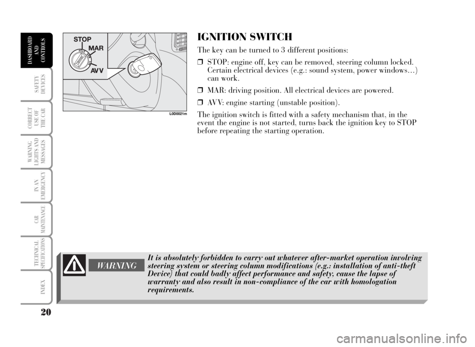
IGNITION SWITCH
The key can be turned to 3 different positions:
❒STOP: engine off, key can be removed, steering column locked.
Certain electrical devices (e.g.: sound system, power windows…)
can work.
❒MAR: driving position. All electrical devices are powered.
❒AVV: engine starting (unstable position).
The ignition switch is fitted with a safety mechanism that, in the
event the engine is not started, turns back the ignition key to STOP
before repeating the starting operation.
L0D0021m
WARNING
It is absolutely forbidden to carry out whatever after-market operation involving
steering system or steering column modifications (e.g.: installation of anti-theft
Device) that could badly affect performance and safety, cause the lapse of
warranty and also result in non-compliance of the car with homologation
requirements.
Page 23 of 346

22
SAFETY
DEVICES
CORRECT
USE OF
THE CAR
WARNING
LIGHTS AND
MESSAGES
IN AN
EMERGENCY
CAR
MAINTENANCE
TECHNICALSPECIFICATIONS
INDEX
DASHBOARD
AND
CONTROLS
Never remove the ignition key while the car is moving. The steering wheel would
automatically lock as soon as you try to turn it. This also applies when the car is
being towed.
WARNING
STEERING COLUMN LOCK
Engaging
When the key is to STOP remove the key and turn
the steering wheel until it locks.Disengaging
Rock the steering wheel slightly as you turn the
ignition key to MAR.
Page 63 of 346

62
SAFETY
DEVICES
CORRECT
USE OF
THE CAR
WARNING
LIGHTS AND
MESSAGES
IN AN
EMERGENCY
CAR
MAINTENANCE
TECHNICALSPECIFICATIONS
INDEX
DASHBOARD
AND
CONTROLS
TRIP COMPUTER
The “Trip computer” displays information relating to the operating status of the car. This function comprises the
“General trip”, concerning the complete mission of the car and “Trip B”, concerning the partial car mission. The
car is delivered with “Trip B” set to “ON”. This function (as shown in the graph below) is contained within the
complete mission. Both functions are resettable. The “General trip” displays the figures relating to Cruising
Range, Travelled Distance, Average fuel consumption, Current fuel consumption, Average speed, Travel time
(driving time). “Trip B” displays information concerning Travel Distance B, Average fuel consumption B,
Average speed B, Travel time B (driving time). The “Trip B” function can be excluded.
Start of journey procedure (reset)
To start a new journey monitored by the “General Trip”, with the key to MAR, press button
{on right
steering column stalk with mode
&(see paragraph “Display control buttons”).
The reset operation in the presence of the screens concerning the “General trip” makes it possible to reset also
the “Trip B”. The reset operation in the presence of the screens concerning only the “Trip B” makes it possible
to reset only the information associated with this function.
IMPORTANT The “Cruising range” information cannot be reset.
Reset TRIP B
End of partial mission
Start of new partial mission
End of partial mission
Start of new partial mission
Reset TRIP B
End of partial mission
Start of new partial mission Reset GENERAL TRIP
End of complete mission - Start of new missionReset GENERAL TRIP
End of complete mission - Start of new mission
End of partial mission
Start of new partial mission Reset TRIP B
Reset TRIP B
TRIP B
TRIP B
TRIP B GENERAL TRIP˙
˙
˙
˙˙
˙
˙ ˙
%= Press “TRIP” button for less than two seconds - &= Press “TRIP” button for over two seconds
Page 70 of 346

69
SAFETY
DEVICES
CORRECT
USE OF
THE CAR
WARNING
LIGHTS AND
MESSAGES
IN AN
EMERGENCY
CAR
MAINTENANCE
TECHNICALSPECIFICATIONS
INDEX
DASHBOARD
AND
CONTROLS
WARNING
Any adjustment of the steering wheel position must be carried out only with the
car stationary and the engine turned off.
STEERING WHEEL ADJUSTMENT
The steering wheel can be adjusted both in height A and axially B.
Proceed as follows:
❒release the lever pulling it towards the steering wheel (position 2);
❒adjust the steering wheel as required;
❒lock the lever pushing it forwards (position 1).
L0D0055m
WARNING
It is absolutely forbidden to carry out whatever after-market operation involving
steering system or steering column modifications (e.g.: installation of anti-theft
device) that could badly affect performance and safety, cause the lapse of
warranty and result in car non-compliance with the regulations in force.
Page 71 of 346

70
SAFETY
DEVICES
CORRECT
USE OF
THE CAR
WARNING
LIGHTS AND
MESSAGES
IN AN
EMERGENCY
CAR
MAINTENANCE
TECHNICALSPECIFICATIONS
INDEX
DASHBOARD
AND
CONTROLS
SEAT ADJUSTMENT
FRONT SEATS
Moving the seat backwards or forwards
Lift the lever A and push the seat forwards or backwards: in the
driving position the arms should rest on the rim of the steering wheel.
Always check that the seat is firmly locked in the runners by trying to
move it back and forth.
Seat height adjustment (driver’s side) (where provided)
Move repeatedly lever B upwards or downwards to achieve the
required height.
IMPORTANT Adjustment must be carried out only seated in the
driver’s seat with the car at a standstill.
Back rest angle adjustment
Move lever D as shown by the arrow, set the back rest in the required
position, then release the lever.
Lumbar adjustment (where provided)
Turn knob C clockwise or counterclockwise to increase or decrease
lumbar adjustment.
After adjustments, always check that the seat is firmly locked in the runners.
WARNING
L0D0041m
L0D0042m
Page 101 of 346

100
SAFETY
DEVICES
CORRECT
USE OF
THE CAR
WARNING
LIGHTS AND
MESSAGES
IN AN
EMERGENCY
CAR
MAINTENANCE
TECHNICALSPECIFICATIONS
INDEX
DASHBOARD
AND
CONTROLS
MAIN BEAM HEADLIGHTS
When the knurled ring is at 2pull the lever towards the steering
wheel (stable position).
The warning light 1on the instrument cluster will come on.
Pulling the lever towards the steering wheel again, the main beams
are turned off (and the dipped beams on).
FLASHING THE HEADLIGHTS
Pull the lever towards the steering wheel (unstable position)
regardless of the position of the knurled ring.
IMPORTANT Check on the display that stable position is not
engaged.
L0D0069m
L0D0070m
Page 102 of 346

101
SAFETY
DEVICES
CORRECT
USE OF
THE CAR
WARNING
LIGHTS AND
MESSAGES
IN AN
EMERGENCY
CAR
MAINTENANCE
TECHNICALSPECIFICATIONS
INDEX
DASHBOARD
AND
CONTROLS
DIRECTION INDICATORS
Move the stalk:
❒up (stable position 1): to engage the right-hand direction
indicator;
❒down (stable position 2): to engage the left-hand direction
indicator.
Warning light ForDwill come on flashing on the instrument cluster.
Indicators are switched off automatically when the steering wheel is
straightened.
If you want the indicator to flash briefly to show that you are about to
change lane, move the stalk up or down without clicking into position
(unstable position). When released the stalk will return to its home
position.
L0D0071m
Page 103 of 346

102
SAFETY
DEVICES
CORRECT
USE OF
THE CAR
WARNING
LIGHTS AND
MESSAGES
IN AN
EMERGENCY
CAR
MAINTENANCE
TECHNICALSPECIFICATIONS
INDEX
DASHBOARD
AND
CONTROLS
“FOLLOW ME HOME” DEVICE
This function allows the illumination of the space in front of the car
for a preset time.
Activation
With the ignition key at STOP or removed, pull the stalk towards the
steering wheel and operate it within 2 minutes from when the engine
is turned off.
At each single movement of the stalk, the staying on of the lights is
extended by 30 seconds up to a maximum of 210 seconds; then the
lights are switched off automatically.
Each time the lever is operated, the 3warning light turns on
together with the message on the display (see section “Warning lights
and messages”).
Deactivation
Keep the stalk pulled towards the steering wheel for more than 2
seconds.
L0D0070m
Page 106 of 346

105
SAFETY
DEVICES
CORRECT
USE OF
THE CAR
WARNING
LIGHTS AND
MESSAGES
IN AN
EMERGENCY
CAR
MAINTENANCE
TECHNICALSPECIFICATIONS
INDEX
DASHBOARD
AND
CONTROLS
“Smart washing” function
Pulling the stalk towards the steering wheel (unstable position)
operates the windscreen washer.
Keeping the stalk pulled for over half a second, with just one
movement it is possible to operate the washer jet and the wiper at the
same time.
Releasing the stalk will stop the washer jet immediately whereas the
wiper stops working four strokes later.
A further “cleaning stroke” after five seconds, completes the wiping
operation.
L0D0074m