headlight Lancia Musa 2008 Owner handbook (in English)
[x] Cancel search | Manufacturer: LANCIA, Model Year: 2008, Model line: Musa, Model: Lancia Musa 2008Pages: 218, PDF Size: 3.68 MB
Page 8 of 218
7
SAFETY
DEVICES
STARTING
AND
DRIVING
WARNING
LIGHTS AND
MESSAGES
IN AN
EMERGENCY
MAINTENANCE
AND CARE
TECHNICALSPECIFICATIONS
INDEX
DASHBOARD
AND CONTROLSDASHBOARD ........................................................ 8
INSTRUMENT PANEL.......................................... 10
SYMBOLS ............................................................. 11
THE LANCIA CODE SYSTEM .............................. 11
THE KEY AND DOOR LOCKING KIT ................. 13
IGNITION DEVICE .............................................. 20
INSTRUMENTS ................................................... 21
MULTIFUNCTIONAL DISPLAY
(on two-line modal panel) ...................................... 22
MULTIFUNCTIONAL DISPLAY
(on three-line modal panel).................................... 25
ADJUSTING THE SEATS ..................................... 38
HEAD RESTRAINTS ............................................ 44
ADJUSTING THE STEERING WHEEL ............... 45
REARVIEW MIRRORS .......................................... 46
HEATING/CLIMATE CONTROL SYSTEM .......... 47
MANUAL CLIMATE CONTROL SYSTEM ........... 48
AUTOMATIC CLIMATE CONTROL
SYSTEM (TWO-ZONE) ....................................... 52
EXTERNAL LIGHTS ........................................... 62
WINDOW WASHING ............................................ 64
CRUISE CONTROL ............................................. 67CEILING LIGHTS ................................................. 69
LIGHT CONTROL BUTTONS .............................. 71
FUEL CUT-OFF INERTIAL SWITCH ................... 72
INTERNAL EQUIPMENT .................................... 73
SMOKERS KIT ...................................................... 75
SUN VISORS ......................................................... 76
SUNROOF ............................................................ 76
POWER WINDOWS ............................................. 78
BOOT .................................................................... 80
BONNET ............................................................... 82
ROOF BARS .......................................................... 83
HEADLIGHTS ...................................................... 84
ABS SYSTEM ....................................................... 85
EOBD SYSTEM .................................................... 86
SOUND SYSTEM .................................................. 87
ACCESSORIES PURCHASED BY THE OWNER .. 88
“DUALDRIVE” ELECTRIC POWER
STEERING SYSTEM ............................................ 89
PARKING SENSORS ............................................ 91
REFUELLING ...................................................... 92
ENVIRONMENTAL PROTECTION ..................... 94
DASHBOARD AND CONTROLS
007-037 MUSA 3ed GB 12-11-2007 11:33 Pagina 7
Page 23 of 218
22
SAFETY
DEVICES
STARTING
AND
DRIVING
WARNING
LIGHTS AND
MESSAGES
IN AN
EMERGENCY
MAINTENANCE
AND CARE
TECHNICALSPECIFICATIONS
INDEX
DASHBOARD
AND CONTROLS
MULTIFUNCTIONAL
DISPLAY
(on two-line modal
panel)
The car can be equipped with a multi-
function display that shows useful in-
formation for car driving according to
the settings made. ENGINE COOLANT
TEMPERATURE GAUGE fig. 25
Warning light Aturns on to indicate
that the temperature of the engine
coolant has remarkably increased. In
this case, stop the engine and go to a
Lancia Dealership. This shows the tem-
perature of the engine coolant fluid and
starts working when the fluid temper-
ature exceeds approx. 50°C. In regular
operating conditions the needle moves
to the different positions allowed inside
the gauge according to the car operat-
ing conditions and management of the
engine cooling system.
IMPORTANT If the needle gets posi-
tioned at the beginning of the scale
(temperature low) and the warning
lightAis on, a failure has occurred in
the system. If this is the case, go to a
Lancia Dealership to have the system
checked.
If the needle indicating the
engine coolant temperature
reaches the red area, stop
the engine immediately and
contact a Lancia Dealership.
fig. 26L0D0027m
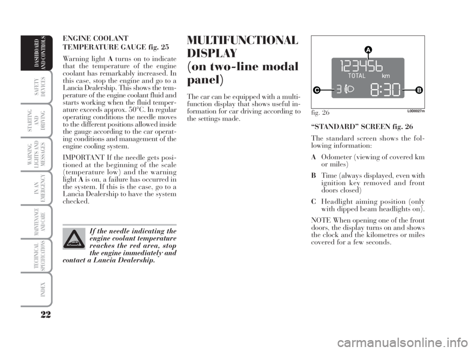
“STANDARD” SCREEN fig. 26
The standard screen shows the fol-
lowing information:
AOdometer (viewing of covered km
or miles)
BTime (always displayed, even with
ignition key removed and front
doors closed)
CHeadlight aiming position (only
with dipped beam headlights on).
NOTE When opening one of the front
doors, the display turns on and shows
the clock and the kilometres or miles
covered for a few seconds.
007-037 MUSA 3ed GB 12-11-2007 11:33 Pagina 22
Page 26 of 218
25
SAFETY
DEVICES
STARTING
AND
DRIVING
WARNING
LIGHTS AND
MESSAGES
IN AN
EMERGENCY
MAINTENANCE
AND CARE
TECHNICALSPECIFICATIONS
INDEX
DASHBOARD
AND CONTROLS
fig. 29L0D09000m
MULTIFUNCTIONAL
DISPLAY
(on three-line
comfort panel)
The car can be equipped with a mul-
tifunction display that shows useful
information for car driving according
to the settings made.
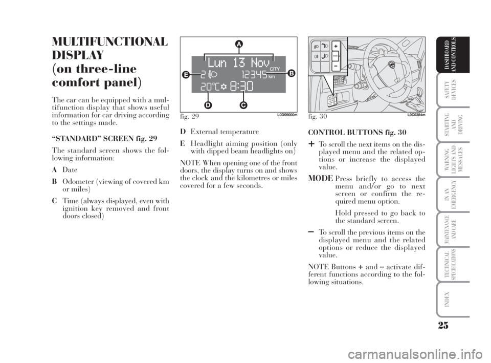
“STANDARD” SCREEN fig. 29
The standard screen shows the fol-
lowing information:
ADate
BOdometer (viewing of covered km
or miles)
CTime (always displayed, even with
ignition key removed and front
doors closed)CONTROL BUTTONS fig. 30
+To scroll the next items on the dis-
played menu and the related op-
tions or increase the displayed
value.
MODEPress briefly to access the
menu and/or go to next
screen or confirm the re-
quired menu option.
Hold pressed to go back to
the standard screen.
–To scroll the previous items on the
displayed menu and the related
options or reduce the displayed
value.
NOTE Buttons
+and–activate dif-
ferent functions according to the fol-
lowing situations. DExternal temperature
EHeadlight aiming position (only
with dipped beam headlights on)
NOTE When opening one of the front
doors, the display turns on and shows
the clock and the kilometres or miles
covered for a few seconds.
fig. 30L0C0384m
007-037 MUSA 3ed GB 12-11-2007 11:33 Pagina 25
Page 27 of 218
26
SAFETY
DEVICES
STARTING
AND
DRIVING
WARNING
LIGHTS AND
MESSAGES
IN AN
EMERGENCY
MAINTENANCE
AND CARE
TECHNICALSPECIFICATIONS
INDEX
DASHBOARD
AND CONTROLS
Adjustment of
headlight aiming device (only with
dipped beam headlights on)
- when the standard screen is enabled,
the headlight aiming device can be
regulated (refer to paragraph “Head-
lights” in this section).
Setup menu
- to scroll the previous and next items
in the menu;
- to increase or decrease values dur-
ing setting operations.
SETUP MENU fig. 31
The menu comprises a series of func-
tions arranged in a cycle which can be
selected through buttons
+and–to
access the different “select” opera-
tions and settings (setup) described in
the following paragraphs.
The setup menu is activated by press-
ing briefly button MODE.
Intermittent pressing of buttons
+and–enables scrolling of the setup menu
options.
Handling modes are different accord-
ing to the characteristic of the option
selected.Selecting the “Set Date”
and “Set time”
– Briefly press button MODEto select
the first value to be changed (e.g.
hours /minutes or year / month /
day).
– Press buttons
+and–(by single
pressing) to select the new setting.
– Briefly press button MODEto store
the new setting and at the same time
go to the next setup menu option. If
the processed option is the last one,
the system brings you back to the pre-
viously selected option of the main
menu.
Prolonged pressing of the
button MODE enables:
– exiting the setup menu page and
saving of the changes already stored
by the driver (and confirmed by
briefly pressing the button MODE).
The setup menu page is timed. Only
the changes saved by the user by
briefly pressing MODEare saved
when the menu is automatically
closed. NOTE If the Connect Nav+ system is
installed, only the following functions
can be adjusted/set from the Instru-
ment Panel: “Brightness”, “Speed
Beep”, Light Sensors” (where pro-
vided), “Seat belt Buzzer” and “Pas-
senger’s Airbag”. The other functions
are displayed on the Connect Nav+
system which is used to adjust/set
them.
Selecting a menu option
– Briefly press button MODEto select
the menu option that needs to be
changed.
– Press buttons
+and–(by single
pressing) to select the new setting.
– Briefly press button MODEto store
the new setting and at the same time
go back to the previously selected
menu option.
007-037 MUSA 3ed GB 12-11-2007 11:33 Pagina 26
Page 30 of 218
29
SAFETY
DEVICES
STARTING
AND
DRIVING
WARNING
LIGHTS AND
MESSAGES
IN AN
EMERGENCY
MAINTENANCE
AND CARE
TECHNICALSPECIFICATIONS
INDEX
DASHBOARD
AND CONTROLS
Adjusting the sensitivity of the
automatic headlight sensor
(Light sensor) (where provided)
This function is used to adjust the
dusk sensor sensitivity according to
three levels (level 1 = minimum, level
2 = medium, level 3 = maximum); the
higher the sensitivity, the lower the
quantity of external light needed to
switch the headlights on. The car is
delivered with this function set to level
“2”.
To change this setting:
– briefly press button MODE: the pre-
viously set level flashes on the display;
– press button +or–for selecting the
desired level;
– briefly press button MODEto go
back to the menu screen or press the
button for a prolonged time to go back
to the standard screen without storing
the settings.Trip B On/Off (Trip B)
Through this option it is possible to
activate (On) or deactivate (Off) the
Trip B (partial trip) display.
For further information see section
“Trip computer”.
For activation / deactivation, proceed
as follows:
– briefly press button MODE: ON or
OFF flashes on the display (according
to previous setting);
– press button +or–for selecting the
desired value;
– briefly press button MODEto go
back to the menu screen or press the
button for a prolonged time to go back
to the standard screen without storing
the settings.Setting the clock (Set time)
This function enables setting of the
clock.
To set the clock proceed as follows:
– briefly press button MODE: the dis-
play shows the “hours” flashing;
– press button +or–to set the clock;
– briefly press button MODE: “min-
utes”starts flashing on the display;
– press button +or–to set the clock.
NOTE The setting increases or de-
creases by one unit each time button
+or–is pressed. Hold the button
pressed to automatically start a quick
increase/decrease of the set value.
Complete the setting by briefly press-
ing the button when the required set-
ting is approached.
– briefly press button MODEto go
back to the menu screen or press the
button for a prolonged time to go
back to the standard screen without
storing the settings.
007-037 MUSA 3ed GB 12-11-2007 11:33 Pagina 29
Page 63 of 218
62
SAFETY
DEVICES
STARTING
AND
DRIVING
WARNING
LIGHTS AND
MESSAGES
IN AN
EMERGENCY
MAINTENANCE
AND CARE
TECHNICALSPECIFICATIONS
INDEX
DASHBOARD
AND CONTROLS
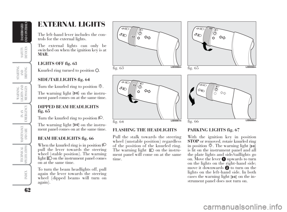
PARKING LIGHTS fig. 67
With the ignition key in position
STOPor removed, rotate knurled ring
in position
6. The warning light 3is lit on the instrument panel and all
the plate lights and side/taillights go
on. Move the lever
aupwards to turn
on the lights on the right-hand side;
move it downwards
bto turn on the
lights on the left-hand side. In both
cases the warning light
3on the in-
strument panel does not turn on. FLASHING THE HEADLIGHTS
Pull the stalk towards the steering
wheel (unstable position) regardless
of the position of the knurled ring.
The warning light
1on the instru-
ment panel will come on at the same
time.
fig. 63L0D0066m
fig. 66L0D0069m
fig. 65L0D0068m
fig. 64L0D0067m
EXTERNAL LIGHTS
The left-hand lever includes the con-
trols for the external lights.
The external lights can only be
switched on when the ignition key is at
MAR.
LIGHTS OFF fig. 63
Knurled ring turned to position
å.
SIDE/TAILLIGHTS fig. 64
Turn the knurled ring to position
6.
The warning light
3on the instru-
ment panel comes on at the same time.
DIPPED BEAM HEADLIGHTS
fig. 65
Turn the knurled ring to position
2.
The warning light
3on the instru-
ment panel comes on at the same time.
BEAM HEADLIGHTS fig. 66
When the knurled ring is in position
2pull the lever towards the steering
wheel (stable position). The warning
light
1on the instrument panel comes
on at the same time.
To turn the beam headlights off, pull
again the lever towards the steering
wheel (dipped beams will turn on
again).
038-094 MUSA 3ed GB 12-11-2007 11:35 Pagina 62
Page 65 of 218

64
SAFETY
DEVICES
STARTING
AND
DRIVING
WARNING
LIGHTS AND
MESSAGES
IN AN
EMERGENCY
MAINTENANCE
AND CARE
TECHNICALSPECIFICATIONS
INDEX
DASHBOARD
AND CONTROLS
WINDOW
WASHING
WINDSCREEN
WASHER/WIPER
The device can work only when the
ignition key is on MAR.
The right lever can take five different
positions:
Awindscreen wiper off
Bintermittent.
With the lever in position B, turn the
knurled ring Fto select one of four
different speeds for the intermittent
operation mode:
,= very slow intermittence
--= slow intermittence
---= mean intermittence
----= fast intermittence When the automatic light sensor is ac-
tivated, the multifunctional display
shows the pre-set sensor sensitivity
level. On this screen it is possible to
adjust the sensitivity level using the
buttons
+and–(seefig. 70).
Deactivation
The main beam headlights will go out
followed by the side/tail lights after
approximately 10 seconds, when the
sensor is deactivated.
If the beam headlights are enabled
(manually by the driver) during au-
tomatic lighting, the beam lights go
off automatically along with the
lights.
IMPORTANT The sensor cannot de-
tect the presence of fog. So, in foggy
conditions, switch the lights on man-
ually.
fig. 70L0D0384m
fig. 71L0C0073m
Ccontinuous slow operation;
Dcontinuous fast operation
Etemporary fast operation
(unstable position).
038-094 MUSA 3ed GB 12-11-2007 11:35 Pagina 64
Page 85 of 218
84
SAFETY
DEVICES
STARTING
AND
DRIVING
WARNING
LIGHTS AND
MESSAGES
IN AN
EMERGENCY
MAINTENANCE
AND CARE
TECHNICALSPECIFICATIONS
INDEX
DASHBOARD
AND CONTROLS
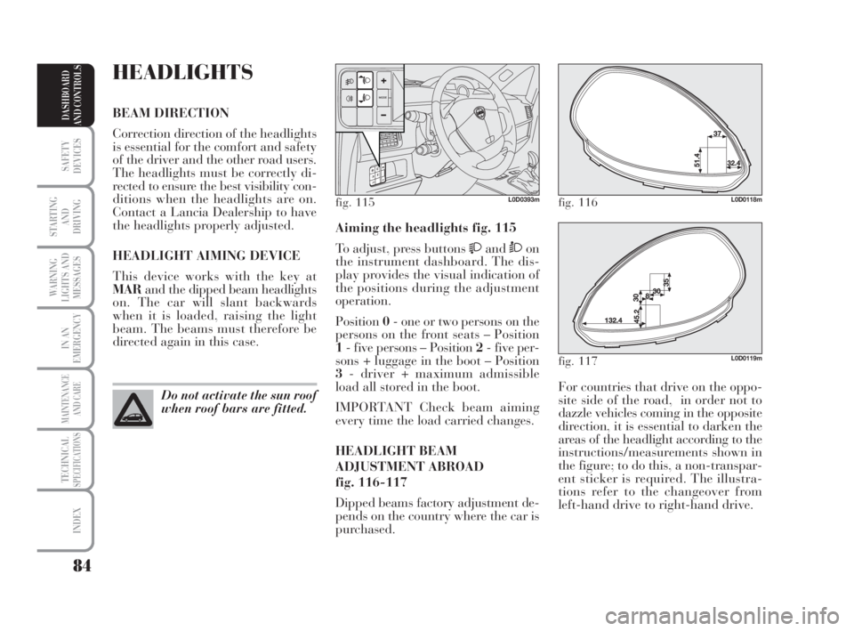
For countries that drive on the oppo-
site side of the road, in order not to
dazzle vehicles coming in the opposite
direction, it is essential to darken the
areas of the headlight according to the
instructions/measurements shown in
the figure; to do this, a non-transpar-
ent sticker is required. The illustra-
tions refer to the changeover from
left-hand drive to right-hand drive. Aiming the headlights fig. 115
To adjust, press buttons
andÒon
the instrument dashboard. The dis-
play provides the visual indication of
the positions during the adjustment
operation.
Position0- one or two persons on the
persons on the front seats – Position
1- five persons – Position 2- five per-
sons + luggage in the boot – Position
3- driver + maximum admissible
load all stored in the boot.
IMPORTANT Check beam aiming
every time the load carried changes.
HEADLIGHT BEAM
ADJUSTMENT ABROAD
fig. 116-117
Dipped beams factory adjustment de-
pends on the country where the car is
purchased.
HEADLIGHTS
BEAM DIRECTION
Correction direction of the headlights
is essential for the comfort and safety
of the driver and the other road users.
The headlights must be correctly di-
rected to ensure the best visibility con-
ditions when the headlights are on.
Contact a Lancia Dealership to have
the headlights properly adjusted.
HEADLIGHT AIMING DEVICE
This device works with the key at
MARand the dipped beam headlights
on. The car will slant backwards
when it is loaded, raising the light
beam. The beams must therefore be
directed again in this case.
Do not activate the sun roof
when roof bars are fitted.
fig. 115L0D0393mfig. 116L0D0118m
fig. 117L0D0119m
038-094 MUSA 3ed GB 12-11-2007 11:35 Pagina 84
Page 119 of 218
118
WARNING
LIGHTS AND
MESSAGES
IN AN
EMERGENCY
MAINTENANCE
AND CARE
TECHNICALSPECIFICATIONS
INDEX
DASHBOARD
AND CONTROLS
SAFETY
DEVICES
STARTING
AND
DRIVING
CONTAINING
RUNNING COSTS
Here are some suggestions which may
help you to keep the running costs of
your car down and lower the amount
of toxic emissions released into the at-
mosphere.
GENERAL CONSIDERATIONS
Car maintenance
Have checks and adjustments carried
out in accordance with the “Service
schedule”.
Tyres
Check tyre pressure regularly at least
once every four weeks: excessively low
pressure will increase consumption
because rolling resistance will be
higher.
Unnecessary loads
Do not travel with an overloaded
boot. The weight of the car (especially
when driving in town) and its trim
greatly affect consumption and sta-
bility.Roof rack/ski rack
Remove the roof rack or the ski rack
from the roof after use. These acces-
sories decrease aerodynamic penetra-
tion of the car and have a negative ef-
fect on consumption. It is better to use
a trailer to transport particularly
bulky objects.
Electric devices
Use electric devices only for the
amount of time needed. Rear heated
window, additional headlights, wind-
screen wipers and heater fan need a
considerable amount of energy, there-
fore increasing the requirement of
current increases fuel consumption
(up to +25% in the urban cycle).
Climate control
The climate control system requires
higher fuel consumption (up to +20%
in average): use the air vents when the
external temperature allows to.
Spoilers
The use of non-certified aerodynamic
items may adversely affect air drag
and consumption levels.DRIVING STYLE
Starting
Do not warm the engine up with the
car standing: the engine warms up
very slowly in these conditions, in-
creasing consumption and emissions.
It is advisable to start off immediately
and slowly keeping the engine speed
down: the engine will warm up much
faster this way.
Unnecessary actions
Avoid revving up when starting at
traffic lights or before stopping the
engine. The latter action, like dou-
bling the clutch, is unnecessary and
causes increase of consumption and
pollution.
Gear selection
Use a higher gear as soon as traffic
and road conditions allow. Using a
low gear for faster acceleration will in-
crease consumption.
In the same way improper use of a
high gear increases consumption,
emissions an engine wear.
113-124 MUSA 3ed GB 12-11-2007 11:37 Pagina 118
Page 126 of 218
125
IN AN
EMERGENCY
MAINTENANCE
AND CARE
TECHNICALSPECIFICATIONS
INDEX
DASHBOARD
AND CONTROLS
SAFETY
DEVICES
STARTING
AND
DRIVING
USE OF
THE CAR
WARNING
LIGHTS AND
MESSAGES
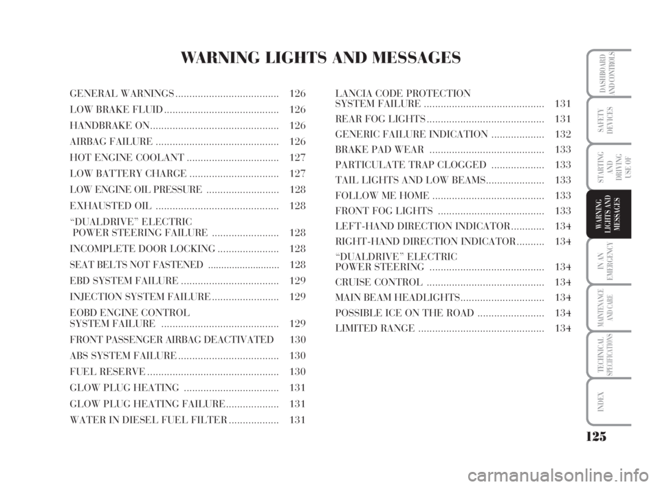
WARNING LIGHTS AND MESSAGES
GENERAL WARNINGS..................................... 126
LOW BRAKE FLUID......................................... 126
HANDBRAKE ON.............................................. 126
AIRBAG FAILURE............................................ 126
HOT ENGINE COOLANT................................. 127
LOW BATTERY CHARGE................................ 127
LOW ENGINE OIL PRESSURE .......................... 128
EXHAUSTED OIL ............................................ 128
“DUALDRIVE” ELECTRIC
POWER STEERING FAILURE ........................ 128
INCOMPLETE DOOR LOCKING...................... 128
SEAT BELTS NOT FASTENED ........................... 128
EBD SYSTEM FAILURE................................... 129
INJECTION SYSTEM FAILURE........................ 129
EOBD ENGINE CONTROL
SYSTEM FAILURE .......................................... 129
FRONT PASSENGER AIRBAG DEACTIVATED 130
ABS SYSTEM FAILURE.................................... 130
FUEL RESERVE............................................... 130
GLOW PLUG HEATING.................................. 131
GLOW PLUG HEATING FAILURE................... 131
WATER IN DIESEL FUEL FILTER.................. 131LANCIA CODE PROTECTION
SYSTEM FAILURE........................................... 131
REAR FOG LIGHTS.......................................... 131
GENERIC FAILURE INDICATION ................... 132
BRAKE PAD WEAR ......................................... 133
PARTICULATE TRAP CLOGGED ................... 133
TAIL LIGHTS AND LOW BEAMS..................... 133
FOLLOW ME HOME........................................ 133
FRONT FOG LIGHTS ...................................... 133
LEFT-HAND DIRECTION INDICATOR............ 134
RIGHT-HAND DIRECTION INDICATOR.......... 134
“DUALDRIVE” ELECTRIC
POWER STEERING ......................................... 134
CRUISE CONTROL .......................................... 134
MAIN BEAM HEADLIGHTS.............................. 134
POSSIBLE ICE ON THE ROAD ........................ 134
LIMITED RANGE ............................................. 134
125-134 MUSA 3ed GB 12-11-2007 11:38 Pagina 125